EP2449626B1 - Selbstkalibrierende konforme phasengesteuerte gruppenantenne - Google Patents
Selbstkalibrierende konforme phasengesteuerte gruppenantenne Download PDFInfo
- Publication number
- EP2449626B1 EP2449626B1 EP10731682.0A EP10731682A EP2449626B1 EP 2449626 B1 EP2449626 B1 EP 2449626B1 EP 10731682 A EP10731682 A EP 10731682A EP 2449626 B1 EP2449626 B1 EP 2449626B1
- Authority
- EP
- European Patent Office
- Prior art keywords
- calibration
- array
- receive
- transmit
- tone
- Prior art date
- Legal status (The legal status is an assumption and is not a legal conclusion. Google has not performed a legal analysis and makes no representation as to the accuracy of the status listed.)
- Active
Links
Images


Classifications
-
- H—ELECTRICITY
- H01—ELECTRIC ELEMENTS
- H01Q—ANTENNAS, i.e. RADIO AERIALS
- H01Q3/00—Arrangements for changing or varying the orientation or the shape of the directional pattern of the waves radiated from an antenna or antenna system
- H01Q3/26—Arrangements for changing or varying the orientation or the shape of the directional pattern of the waves radiated from an antenna or antenna system varying the relative phase or relative amplitude of energisation between two or more active radiating elements; varying the distribution of energy across a radiating aperture
- H01Q3/267—Phased-array testing or checking devices
Definitions
- the present disclosure relates to self calibration.
- it relates to self calibrating conformal (non-flat) phased arrays.
- the first approach is a mechanical approach that involves embedding a mesh of mechanical sensors across the array to measure strain and mechanical movement of the array.
- the second approach is a radio frequency (RF) approach that involves measuring the beam pattern externally and, from those measurements, inferring the element movement across the array.
- RF radio frequency
- the first approach the mechanical approach, is quite expensive and requires a very complex calibration phase to turn mechanical strain readings into element movement.
- the mechanical approach relies on embedding mechanical sensors within an electronic substrate, which is a difficult integration task.
- global errors from local strain readings increase as the array size increases. Additionally, without feedback generated from the actual beam pattern, this approach can drift out of calibration.
- the second approach uses externally mounted horns or antennas to receive a calibration transmission from the array at certain angles. From these measurements, beam pattern anomalies can be detected and some phase corrections may be attempted. However, without a detailed knowledge of the spatial pattern at many simultaneous points, it is impossible to estimate flexure across the array to any great degree of precision. Because of the limited positions in which an external antenna could be mounted on an aircraft within viewing angles of the conformal array, this greatly limits the ability to do in-flight calibration and flexure estimation.
- a self calabrating phased array is known from US2004/0061644 A1 .
- the present disclosure relates to an apparatus, system, and method for self calibrating conformal (non-flat) phased arrays.
- Antenna beam patterns of phased arrays are degraded by continuously changing flexure of the array.
- the array In order to compensate for the flexure, the array must be continuously recalibrated to determine the updated position of each array element.
- the system of the present disclosure addresses the challenge of determining the updated positions of the array elements by providing a means for estimating the flexure of a conformal array in real-time in order for a beam-pointing algorithm to be adapted to the physical displacement of each array element.
- the disclosed system allows for an increase in the performance of the array, including maximizing gain and minimizing sidelobe levels and beamwidth.
- the system for a self calibrating conformal (non-flat) phased array involves a self calibrating conformal phased array, comprising: a plurality of transmit/receive elements; a plurality of embedded, calibration transmit/receive elements scattered across the array; wherein the calibration transmit/receive elements are used to track any physical calibration transmit/receive element's relative position change caused by array flexure; and at least one back-end processor; wherein each of the calibration transmit/receive elements transmit a tone using a small antenna; and wherein the other calibration transmit/receive elements receive the tone using small antennas.
- the small antennas are small monopole antennas. In at least one embodiment, the small monopole antennas are positioned vertical to the array.
- the other calibration transmit/receive elements that receive the tone measure the phase of the received tone. Also, in at least one embodiment, at least one back-end processor uses the measured phases to determine differential phases from a phase calibration table. Additionally, at least one back-end processor uses the differential phases to compute a change in apparent location of each transmitting calibration transmit/receive element.
- a method for tracking and calibrating a physical calibration element's relative position change caused by array flexure comprises transmitting a tone from each calibration transmit/receive element using a small antenna, and receiving the tone by other calibration transmit/receive elements using small antennas. In some embodiments, the method further comprises measuring the phase of the received tone; computing the differential phase from a phase calibration table; and computing the change in apparent location of each transmitting calibration transmit/receive element.
- the small antenna transmitting the tone is a small monopole antenna.
- the small monopole antenna is positioned vertical to the array.
- the small antennas receiving the tone are small monopole antennas.
- the small monopole antennas are positioned vertical to the array.
- at least one back-end processor is used to compute the differential phase from the phase calibration table.
- a system for self calibrating comprises a plurality of embedded, calibration transmit/receive elements scattered across a structure, and at least one back-end processor.
- the calibration transmit/receive elements are used to track any physical calibration transmit/receive element's relative position change caused by structure flexure.
- each of the calibration transmit/receive elements transmit a tone using small antennas, and the other calibration transmit/receive elements receive the tone using small antennas.
- the small antennas are small monopole antennas. In at least one embodiment, the small monopole antennas are positioned vertical to the structure.
- the other calibration transmit/receive elements that receive the tone measure the phase of the received tone.
- at least one back-end processor uses the measured phases to determine differential phases from a phase calibration table.
- at least one back-end processor uses the differential phases to compute a change in apparent location of each transmitting calibration transmit/receive element.
- the disclosed array and calibration method have many advantages, including allowing calibration transmit/receive (TR) elements to be placed anywhere on the array, wherever it is most convenient for the array element layout as well as wherever array movement needs to be most closely monitored. These many advantages are described in detail below.
- a first advantage is that the calibration transmit/receive (TR) elements can operate at a much higher radio frequency (RF) than the rest of the array. Not only can these elements be made much smaller than the normal array elements, and possibly positioned in gaps within the original array, but these elements can be operated at the same time as the main array with sufficient front-end filtering. Thus, blanking intervals are not needed for calibration.
- Table 1 below shows a listing of possible perturbation and monopole lengths for the calibration transmit/receive (TR) elements of the present disclosure.
- a second advantage is that the choice of calibration element operation frequencies is flexible, and can be chosen based on both maximum flexure distances and sufficient frequency offset from the original array so that interference is minimized.
- a third advantage is that the calibration element locations can be chosen based on airframe structural members to which the array is attached. A study of vibration modes of the array manifold can be used to position the calibration elements to get the most accuracy from them.
- a fourth advantage is that the calibration transmit (TX) elements only transmit a tone and, thus, no complex modulation is required at each element.
- a fifth advantage is that each calibration receive (RX) element is also very simple. Each calibration receive (RX) element measures and sends to the back-end processor a phase difference measurement between its own clock and that of the received calibration signal.
- a sixth advantage is that the clock distribution is very simple for the calibration transmit/receive (TR) elements.
- a single clock can be distributed to all of the calibration transmit/receive (TR) elements without the need for synchronization across the array. All that is required is that the clock phases remain constant at the calibration transmit/receive (TR) elements.
- a seventh advantage is that there are several different ways to compute the element positions.
- One method for the computation is taught in the present disclosure, but any other distributed-position estimation method could be employed for this system.
- An eighth advantage is that the geometry of the conformal array is used in an essential way.
- the "non-flat” or “non-two-dimensional (non-2D)" nature of the conformal array allows for it to have diversity in the boresight direction of the array, which is due to the curvature of the conformal array. This allows for estimation of the third dimension of the array flexure.
- a pure flat two-dimensional (2D) array with no external components could not be used to estimate flexure in the third dimension due to the inherent ambiguity of not being able to distinguish inward flexure from outward flexure.
- the methods and apparatus disclosed herein provide an operative system for self calibration. Specifically, this system allows for self calibration for conformal (non-flat) phased arrays.
- the system of the present disclosure provides a means for estimating the flexure of a conformal array in real-time in order for a beam-pointing algorithm to be adapted to the physical displacement of each array element.
- the disclosed system allows for an increase in the performance of the array, including maximizing gain and minimizing sidelobe levels and beamwidth.
- the system of the present disclosure involves a self calibrating conformal array that uses its non-flat array shape to perform three-dimensional (3D) flexure estimation. From the flexure estimation, calibration settings are updated to be used in beam pointing algorithms for the array.
- 3D three-dimensional
- the array of the disclosed system employs a small number of embedded calibration transmit/receive (TR) elements scattered across the array. After initial calibration of the array, any physical calibration element's relative position changes caused by array flexure will be tracked through a simple process.
- the process includes the following steps: each calibration transmit/receive (TR) element successively transmits a tone using a small monopole antenna that is positioned vertical to the array manifold; every other calibration transmit/receive (TR) element receives this tone and measures the phase; at least one back-end processor uses the measured phases to determine the differential phases from the phase calibration table; and at least one back-end processor computes the change in apparent location of each transmitting calibration transmit/receive (TR) element.
- the disclosed system of utilizing a number of embedded calibration transmit/receive (TR) elements to determine flexure may be employed with various other structures than antenna arrays.
- Types of structures that may be used with the disclosed system include, but are not limited to, bridges, buildings, and spacecraft housing.
- FIG. 1 illustrates a self calibrating conformal array with interspersed calibration transmit/receive (TR) elements, in accordance with at least one embodiment of the present disclosure.
- a self calibrating array 100 is shown having six interspersed calibration transmit/receive (TR) elements 101, 102, 103, 104, 105, 106.
- Each calibration transmit/receive (TR) element 101, 102, 103, 104, 105, 106 is depicted as including a monopole antenna 110, 115, 120, 125, 130, 135 that is positioned vertical to the array.
- FIG. 2 depicts a block diagram of a calibration transmit/receive (TR) element, in accordance with at least one embodiment of the present disclosure.
- the block diagram 200 shows the communication units that are included in an individual calibration transmit/receive (TR) element.
- waveform 205 is inputted into a clock multiplier 210.
- the output of a frequency control unit 215 is inputted into the clock multiplier 210.
- the output of the clock multiplier 210 is inputted into a mixer 225.
- the output of a time control unit 220 is inputted into the mixer 225.
- the output of the mixer is inputted separately into a power amplifier 230 and a quadrature mixer 245.
- the power amplifier 230 transmits 260 a signal through the calibration element's antenna 235.
- the calibration element's antenna 235 also receives 265 signals. After the calibration element's antenna 235 receives 265 a signal, the received signal is inputted into a low noise amplifier (LNA) 240. The output of the LNA is inputted into the quadrature mixer 245. The output of the quadrature mixer 245 is then inputted into an integrating phase estimator 250, which outputs a phase estimate 255 of the received signal.
- LNA low noise amplifier
- Table 1 above shows the maximum unambiguous perturbation length that can be measured for a given frequency of calibration tone.
- This table also shows the A/4 length of an optional monopole antenna, which is attached to each calibration array element and used to help with the reception and transmission of calibration tones across the curved array. It is evident from the table that higher frequencies allow for shorter ⁇ /4 monopoles, but have greater problems with ambiguities for perturbation lengths. Thus, a design trade is necessary when choosing the best calibration frequency to be used for the system.
- Flexure estimation involves a design step and a two-step calibration process.
- the design step is discussed in detail in the Element Displacement Estimation section below.
- the calibration process includes a first step and a second step.
- the first step of the calibration process is the initial calibration, where clock synchronization effects and array propagation effects are estimated.
- the second step of the calibration process requires subsequent ongoing adaptive calibration to estimate the physical element movement and the corresponding array beam-forming changes over time.
- the system estimates flexure of a conformal array in real-time so that the beam pointing algorithm can be continuously adapted to the displacement of each array element. This increases the performance of the array, which includes maximizing the gain as well as minimizing the sidelobe levels and beamwidth.
- Flexure estimation using element perturbation estimation can be computed using modifications to algorithms from many different areas of study.
- One area of study involves guidance and navigation algorithms that are used for solving global positioning system (GPS) equations.
- GPS global positioning system
- Many different algorithms used for solving GPS have been published in the area of guidance and navigation. These algorithms use range measurements from the GPS satellites in view of a GPS receiver to compute the location and clock offset of the GPS receiver. By reversing this picture, similar equations can be used to compute calibration element locations from phase change estimates that are converted to ranges.
- sensor network localization Another area of study involves sensor network localization. Many papers have been published in the area of sensor network localization. The object of sensor network localization is to use range/delay estimates to self-locate all of the sensors in a sensor network. Theses algorithms range from iterative to subnetwork methods to full network optimization algorithms. Equations similar to these algorithms may be used for calculating the calibration element locations for the disclosed system.
- Multilateration occurs when several receivers simultaneously receive and geolocate a signal transmission.
- These algorithms typically use time-of-arrival (TOA) for cooperative or time-difference-of-arrival (TDOA) for noncooperative signals to estimate the location of the signal transmission.
- TOA time-of-arrival
- TDOA time-difference-of-arrival
- This analytic method is from the area of study that involves guidance and navigation algorithms that are used for solving global positioning system (GPS) equations. It should be noted that many different analytic methods may be utilized to estimate the calibration element locations for alternative embodiments of the disclosed system.
- GPS global positioning system
- the temporary notation is used here to distinguish the two distinct roles played by transmitter and receiver with "unknown” and “known” positions.)
- the following method produces an estimate of ⁇ x given the positions ⁇ s i ⁇ (where each ⁇ s i is assumed to be zero) and phase delay measurements ⁇ p i
- Each transmitter and receiver is driven by and coherent with a single clock that has been distributed over the entire array.
- These offsets can be measured during the initial laboratory calibration by transmitting on node i and receiving on node j and then reversing transmitter and receiver. If t is the propagation time between the two antenna phase centers, then the first transmission sees a delay of t + b j - b i while the other sees t + b i - b j . This allows the solution of the clock offset difference b i - b j . With the reference node given a "zero" clock offset, all offsets can be solved for. In fact, this process measures all of the different contributing biases and estimates the total differential bias from node i to node j .
- n 1 x 4 vectors a i s ⁇ T i , t i .
- a,b ⁇ a 1 b 1 + a 2 b 2 + a 3 b 3 -a 4 b 4 .
- the sequence of calibration element design steps is as follows.
- Step 1 estimate maximum displacement of any point from initial (unstressed) location within active portion of conformal array.
- Step 2 from mechanical modes of the enveloping airframe structure, estimate the minimum number of sampling points necessary to characterize the flexure and define where they can be placed on the conformal array.
- Step 3 from the sampling points, estimate the maximum range differences possible for the processing neighborhoods, denoted by ⁇ ⁇ R max .
- Step 5 design the monopole antennas with physical offsets from the honeycomb array structure so that the requirements in the following areas are met.
- the first requirement involves aircraft performance requirements (e.g., airflow resistance), which require a limited offset distance.
- the second requirement involves limitations of the geometric diversity of the conformal array in the z dimension (boresight), which will limit the ultimate accuracy. Offsetting the monopole phase centers can further increase the z dimension diversity. A design trade is necessary to determine if the accuracy will be sufficient.
- the third requirement involves multipath and electromagnetism (EM) blockage considerations, which will limit the range of each calibration transmission (e.g., the array may be curved so much that one part of the conformal array is not visible from the other side).
- the amount of blockage determines the neighborhoods of the elements on the array that are capable of calibration operation.
- Step 1 is the initial calibration that is used to estimate the calibration element clock and miscellaneous biases, as were described above.
- Step 2 involves computing integer ⁇ n i ⁇ wavelength estimates for each inter-calibration element distance.
- Step 3 involves estimating the appropriate array calibration element neighborhoods. This step defines for each transmitting node k, the set of receiving nodes appropriate for calibration. As such, there must be a direct path between the two nodes, and the signal strength must be high enough for good phase estimates. The amount of curvature of the array, antenna heights, and flexure sampling density from the calibration elements all effect the neighborhood size.
- Step 1 for each calibration transmitter node i, solve for its position and, hence, its displacement from the original designed position by assuming all of the receiving nodes have no displacement from their original designed position. This produces a set ⁇ x i ⁇ of displacement estimates.
- Step 2 subtract the displacement estimate from each node's position.
- Step 3 repeat step 1, and solve for the displacement estimates with the new updated element positions.
- Step 4 repeat steps 1 through 3 until the overall range errors across the array have been reduced below a predefined threshold value.
- the algorithm described above has been implemented with simulated arrays.
- the simulation results show how well the algorithm operates on simulated flexures.
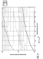
- FIG. 4 illustrates a chart 400 showing the performance of flexure estimation as a function of noise and uncorrected biases, in accordance with at least one embodiment of the present disclosure.
- this figure shows the performance as a function of noise for a particular 8 x 16 cylindrical array.
- the z axis is perpendicular to the array, which is wrapped onto a 1.8 meter radius (representing a similar fuselage to a 74 inch diameter 737-800), but is mostly flat.
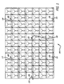
- FIG. 3 shows a plot 300 that indicates the locations of the calibration transmit/receive (TR) elements for this particular cylindrical array.
- the noise and biases are introduced as a uniform random error in the range measurements.
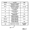
- the various parameter settings used for this simulation are shown in FIG. 5 .
- the z axis perturbation error is much greater due to the limited diversity of the calibration array in the z dimension. As such, the diversity of calibration element locations will drive the accuracy of the final perturbation estimates.
Landscapes
- Variable-Direction Aerials And Aerial Arrays (AREA)
Claims (10)
- Selbstkalibrierendes konformes Phased-Array (100) mit:einer Vielzahl von Sende-/Empfangselementen (101, 102, 103, 104, 105, 106);einer Vielzahl eingebetteter Kalibrierungssende-/empfangselemente (101, 102, 103, 104, 105, 106), die über das Array verteilt sind;wobei die Kalibrierungssende-/empfangselemente (101, 102, 103, 104, 105, 106) verwendet werden, um die relative Positionsänderung jedes physikalischen Kalibrierungssende-/empfangselements, die durch eine Biegung des Arrays verursacht ist, zu verfolgen; undwenigstens einem Backend-Prozessor;dadurch gekennzeichnet, dassjedes der Kalibrierungssende-/empfangselemente (101, 102, 103, 104, 105, 106) dazu ausgelegt ist, einen Ton unter Verwendung einer kleinen Antenne (110, 115, 120, 125, 130, 135) zu senden; undwobei die anderen Kalibrierungssende-/empfangselemente (101, 102, 103, 104, 105, 106) dazu ausgelegt sind, den Ton unter Verwendung kleiner Antennen (110, 115, 120, 125, 130, 135) zu empfangen.
- Selbstkalibrierendes konformes Phased-Array (100) nach Anspruch 1, wobei die anderen Kalibrierungssende-/empfangselemente, die den Ton empfangen, dazu ausgelegt sind, die Phase des empfangenen Tons zu messen.
- Selbstkalibrierendes konformes Phased-Array (100) nach Anspruch 2, wobei der wenigstens eine Backend-Prozessor dazu ausgelegt ist, die gemessenen Phasen zu verwenden, um differentielle Phasen aus einer Phasenkalibrierungstabelle zu ermitteln.
- Selbstkalibrierendes konformes Phased-Array (100) nach Anspruch 3, wobei der wenigstens eine Backend-Prozessor dazu ausgelegt ist, die differentiellen Phasen zu verwenden, um eine Veränderung des offensichtlichen Standorts jedes sendenden
Kalibrierungssende-/empfangselements (101, 102, 103, 104, 105, 106) zu berechnen. - Verfahren zum Verfolgen und Kalibrieren der von einer Biegung eines Arrays verursachten relativen Positionsänderung eines physikalischen Kalibrierungselements, wobei das Verfahren umfasst:Senden eines Tons von jedem Kalibrierungssende-/empfangselement (101, 102, 103, 104, 105, 106) unter Verwendung einer kleinen Antenne (110, 115, 120, 125, 130, 135);Empfangen des Tons durch andere Kalibrierungssende-/empfangselemente (101, 102, 103, 104, 105, 106) unter Verwendung kleiner Antennen (110, 115, 120, 125, 130, 135);Messen der Phase des empfangenen Tons;Berechnen einer differentiellen Phase aus einer Phasenkalibrierungstabelle; undBerechnen einer Veränderung des offensichtlichen Standorts jedes sendenden Kalibrierungssende-/empfangselements (101, 102, 103, 104, 105, 106).
- Verfahren nach Anspruch 5, wobei wenigstens ein Backend-Prozessor verwendet wird, um die differentielle Phase aus der Phasenkalibrierungstabelle zu berechnen.
- Selbstkalibrierendes System, wobei das System aufweist:eine Vielzahl eingebetteter Kalibrierungssende-/empfangselemente (101, 102, 103, 104, 105, 106), die über eine Struktur verteilt sind;wobei die Kalibrierungssende-/empfangselemente (101, 102, 103, 104, 105, 106) verwendet werden, um die relative Positionsänderung jedes physikalischen Kalibrierungssende-/empfangselements, die durch eine Biegung des Arrays verursacht ist, zu verfolgen; undwenigstens einen Backend-Prozessor;dadurch gekennzeichnet, dassjedes der Kalibrierungssende-/empfangselemente (101, 102, 103, 104, 105, 106) dazu ausgelegt ist, einen Ton unter Verwendung kleiner Antennen (110, 115, 120, 125, 130, 135) zu senden; undwobei die anderen Kalibrierungssende-/empfangselemente (101, 102, 103, 104, 105, 106) dazu ausgelegt sind, den Ton unter Verwendung kleiner Antennen (110, 115, 120, 125, 130, 135) zu empfangen.
- Selbstkalibrierendes System nach Anspruch 7, wobei die anderen Kalibrierungssende-/empfangselemente, die den Ton empfangen, dazu ausgelegt sind, die Phase des empfangenen Tons zu messen.
- Selbstkalibrierendes System nach Anspruch 8, wobei der wenigstens eine Backend-Prozessor dazu ausgelegt ist, die gemessenen Phasen zu verwenden, um differentielle Phasen aus einer Phasenkalibrierungstabelle zu ermitteln.
- Selbstkalibrierendes System nach Anspruch 9, wobei der wenigstens eine Backend-Prozessor dazu ausgelegt ist, die differentiellen Phasen zu verwenden, um eine Veränderung des offensichtlichen Standorts jedes sendenden Kalibrierungssende-/empfangselements zu berechnen.
Applications Claiming Priority (2)
| Application Number | Priority Date | Filing Date | Title |
|---|---|---|---|
| US12/497,491 US8184042B2 (en) | 2009-07-02 | 2009-07-02 | Self calibrating conformal phased array |
| PCT/US2010/040674 WO2011002934A1 (en) | 2009-07-02 | 2010-06-30 | Self calibrating conformal phased array |
Publications (2)
| Publication Number | Publication Date |
|---|---|
| EP2449626A1 EP2449626A1 (de) | 2012-05-09 |
| EP2449626B1 true EP2449626B1 (de) | 2013-08-07 |
Family
ID=42668711
Family Applications (1)
| Application Number | Title | Priority Date | Filing Date |
|---|---|---|---|
| EP10731682.0A Active EP2449626B1 (de) | 2009-07-02 | 2010-06-30 | Selbstkalibrierende konforme phasengesteuerte gruppenantenne |
Country Status (3)
| Country | Link |
|---|---|
| US (1) | US8184042B2 (de) |
| EP (1) | EP2449626B1 (de) |
| WO (1) | WO2011002934A1 (de) |
Families Citing this family (22)
| Publication number | Priority date | Publication date | Assignee | Title |
|---|---|---|---|---|
| US8184042B2 (en) * | 2009-07-02 | 2012-05-22 | The Boeing Company | Self calibrating conformal phased array |
| US8686896B2 (en) * | 2011-02-11 | 2014-04-01 | Src, Inc. | Bench-top measurement method, apparatus and system for phased array radar apparatus calibration |
| DE102012204174B4 (de) * | 2012-03-16 | 2022-03-10 | Rohde & Schwarz GmbH & Co. Kommanditgesellschaft | Verfahren, System und Kalibrierobjekt zur automatischen Kalibrierung einer bildgebenden Antennenanordnung |
| US10185022B1 (en) * | 2013-05-17 | 2019-01-22 | Mano D. Judd | Boresight method |
| US9866336B2 (en) * | 2015-06-17 | 2018-01-09 | Google Llc | Phased array antenna self-calibration |
| CN108370258B (zh) | 2015-09-10 | 2020-07-10 | 蓝色多瑙河系统有限公司 | 校准串行互连 |
| US10181943B2 (en) * | 2016-09-29 | 2019-01-15 | Blue Danube Systems, Inc. | Distributing coherent signals to large electrical distances over serial interconnections |
| TWI678846B (zh) | 2018-11-15 | 2019-12-01 | 財團法人工業技術研究院 | 天線裝置及校正天線裝置的方法 |
| CN109782238B (zh) * | 2018-11-19 | 2022-07-26 | 西北工业大学 | 一种传感器阵列阵元幅相响应和阵元位置的联合校准方法 |
| US10680725B1 (en) * | 2019-05-21 | 2020-06-09 | Qualcomm Incorporated | Self-calibration of phased array |
| US11482779B2 (en) | 2019-07-12 | 2022-10-25 | Raytheon Company | Minimal phase matched test target injection for parallel receiver phase and amplitude alignment |
| CN110398711A (zh) * | 2019-08-01 | 2019-11-01 | 天津工业大学 | 一种声呐共形阵基于阵列流形测量的方向图综合方法 |
| CN110988550B (zh) * | 2019-12-17 | 2022-04-01 | 合肥诺宸智能装备有限公司 | 一种产品信号自动测试平台 |
| US12040553B1 (en) * | 2020-02-13 | 2024-07-16 | Ast & Science, Llc | Compensating oscillations in a large-aperture phased array antenna |
| US11722211B1 (en) | 2020-02-13 | 2023-08-08 | Ast & Science, Llc | AOCS system to maintain planarity for space digital beam forming using carrier phase differential GPS, IMU and magnet torques on large space structures |
| US11444376B2 (en) * | 2020-06-05 | 2022-09-13 | Analog Devices International Unlimited Com Pany | Systems and methods for calibrating arrays of dual-polarization antenna elements |
| CN112433218B (zh) * | 2020-11-17 | 2024-02-13 | 海鹰企业集团有限责任公司 | 一种舰用共形阵虚拟障板的实现方法 |
| CN113014294B (zh) * | 2021-03-12 | 2023-02-07 | 西安电子工程研究所 | 一种两维相控阵微波前端校准网络及方法 |
| US12413319B2 (en) * | 2022-08-12 | 2025-09-09 | Northrop Grumman Systems Corporation | Testing a signal path |
| DE102022123305B3 (de) | 2022-09-13 | 2023-12-28 | Deutsches Zentrum für Luft- und Raumfahrt e.V. | Richtantenne mit Vermessungssystem zur automatischen Phasenlageneinstellung |
| CN115588851B (zh) * | 2022-12-12 | 2023-04-11 | 中国电子科技集团公司第十研究所 | 球面相控阵天线的阵元通道相位标校的有效性验证方法 |
| CN117630894B (zh) * | 2024-01-24 | 2024-04-12 | 山东省科学院海洋仪器仪表研究所 | 一种多波束声呐平均阵元间距校准方法 |
Family Cites Families (26)
| Publication number | Priority date | Publication date | Assignee | Title |
|---|---|---|---|---|
| US5412414A (en) * | 1988-04-08 | 1995-05-02 | Martin Marietta Corporation | Self monitoring/calibrating phased array radar and an interchangeable, adjustable transmit/receive sub-assembly |
| US5248982A (en) * | 1991-08-29 | 1993-09-28 | Hughes Aircraft Company | Method and apparatus for calibrating phased array receiving antennas |
| US6157343A (en) * | 1996-09-09 | 2000-12-05 | Telefonaktiebolaget Lm Ericsson | Antenna array calibration |
| US5572219A (en) | 1995-07-07 | 1996-11-05 | General Electric Company | Method and apparatus for remotely calibrating a phased array system used for satellite communication |
| US5682165A (en) * | 1996-05-02 | 1997-10-28 | Hughes Electronics | Active array self calibration |
| SE509434C2 (sv) * | 1997-05-16 | 1999-01-25 | Ericsson Telefon Ab L M | Anordning och förfarande vid antennkalibrering |
| US6088385A (en) * | 1997-06-30 | 2000-07-11 | Integrated Telecom Express | Flexible and scalable rate ADSL transceiver and system |
| US6037898A (en) * | 1997-10-10 | 2000-03-14 | Arraycomm, Inc. | Method and apparatus for calibrating radio frequency base stations using antenna arrays |
| US6252542B1 (en) * | 1998-03-16 | 2001-06-26 | Thomas V. Sikina | Phased array antenna calibration system and method using array clusters |
| US6208287B1 (en) * | 1998-03-16 | 2001-03-27 | Raytheoncompany | Phased array antenna calibration system and method |
| US6515616B1 (en) * | 1999-04-30 | 2003-02-04 | Metawave Communications Corporation | System and method for aligning signals having different phases |
| US6333712B1 (en) | 1999-11-04 | 2001-12-25 | The Boeing Company | Structural deformation compensation system for large phased-array antennas |
| SE515141C2 (sv) * | 2000-03-22 | 2001-06-18 | Ericsson Telefon Ab L M | Självkalibrering av matarledningar för gruppantenner |
| US6320538B1 (en) | 2000-04-07 | 2001-11-20 | Ball Aerospace & Technologies Corp. | Method and apparatus for calibrating an electronically scanned reflector |
| JP2002135186A (ja) * | 2000-10-24 | 2002-05-10 | Sony Corp | 受信機 |
| AU2002313608A1 (en) * | 2002-08-16 | 2004-03-03 | Stichting Astron | Calibration method, device and computer program |
| US20040061644A1 (en) | 2002-09-11 | 2004-04-01 | Lockheed Martin Corporation | CCE calibration with an array of calibration probes interleaved with the array antenna |
| US7023378B2 (en) * | 2004-01-20 | 2006-04-04 | Harris Corporation | Self-calibrating wideband phase continuous synthesizer and associated methods |
| US7576686B2 (en) * | 2006-08-07 | 2009-08-18 | Garmin International, Inc. | Method and system for calibrating an antenna array for an aircraft surveillance system |
| US7884772B2 (en) | 2007-05-07 | 2011-02-08 | Lockheed Martin Corporation | Radar apparatus and alignment sensor |
| US8085189B2 (en) * | 2007-08-31 | 2011-12-27 | Bae Systems Plc | Antenna calibration |
| US7714775B2 (en) * | 2007-12-17 | 2010-05-11 | The Boeing Company | Method for accurate auto-calibration of phased array antennas |
| US8472883B2 (en) * | 2008-09-23 | 2013-06-25 | Intel Mobile Communications GmbH | Self calibration method for radio equipment with receive and transmit circuitry |
| US7911376B2 (en) * | 2009-04-01 | 2011-03-22 | Sony Corporation | Systems and methods for antenna array calibration |
| US20100321233A1 (en) * | 2009-06-18 | 2010-12-23 | Alvarion Ltd. | Method for calibrating antenna arrays |
| US8184042B2 (en) * | 2009-07-02 | 2012-05-22 | The Boeing Company | Self calibrating conformal phased array |
-
2009
- 2009-07-02 US US12/497,491 patent/US8184042B2/en active Active
-
2010
- 2010-06-30 WO PCT/US2010/040674 patent/WO2011002934A1/en not_active Ceased
- 2010-06-30 EP EP10731682.0A patent/EP2449626B1/de active Active
Also Published As
| Publication number | Publication date |
|---|---|
| US8184042B2 (en) | 2012-05-22 |
| EP2449626A1 (de) | 2012-05-09 |
| US20110001660A1 (en) | 2011-01-06 |
| WO2011002934A1 (en) | 2011-01-06 |
Similar Documents
| Publication | Publication Date | Title |
|---|---|---|
| EP2449626B1 (de) | Selbstkalibrierende konforme phasengesteuerte gruppenantenne | |
| US10663563B2 (en) | On-site calibration of array antenna systems | |
| EP1828803B1 (de) | System und verfahren zur kalibrierung von radar-arrays | |
| US10571544B2 (en) | Direction finding using signal power | |
| US7436359B1 (en) | Method for single satellite geolocation of emitters using an ambiguous interferometer array | |
| CN107315183B (zh) | 导航卫星阵列天线接收系统的校准方法 | |
| US7969358B2 (en) | Compensation of beamforming errors in a communications system having widely spaced antenna elements | |
| EP3521842A1 (de) | Verfahren und systeme für esa-metrologie | |
| CN115061156A (zh) | 一种基于组合导航的阵列天线抗卫星导航欺骗方法及系统 | |
| EP1910864B1 (de) | System und verfahren zum positionieren eines transponders | |
| Sippel et al. | In-situ calibration of antenna arrays within wireless locating systems | |
| EP1188066A1 (de) | Navigationsverfahren mittels schmalbandsignalen | |
| EP1910860B1 (de) | System und verfahren zur positionierung | |
| Fulton et al. | Calibration of a digital phased array for polarimetric radar | |
| CN109975620A (zh) | 一种全空域相控阵被测天线旋转模拟校准系统及方法 | |
| Ali et al. | Time of arrival estimation for WLAN indoor positioning systems using matrix pencil super resolution algorithm | |
| CN104267420A (zh) | 一种星载对运动目标的三维定位方法、装置和系统 | |
| US8294616B1 (en) | Using antennas separated in flight direction to avoid effect of emitter clock drift in geolocation | |
| CN116736245A (zh) | 一种相位补偿方法、装置、设备及存储介质 | |
| Wang et al. | Measurement and analysis of antenna pattern for MIMO HF surface wave radar | |
| EP3846358B1 (de) | System und verfahren zur kalibrierung einer antenne | |
| Urzaiz et al. | Digital beamforming on receive array calibration: Application to a persistent X-band surface surveillance radar | |
| Anton et al. | Analysis of a distributed array system for satellite acquisition | |
| Huang et al. | In-field calibration of passive array receiver using detected target | |
| CN106507953B (zh) | 卫星被动测轨方法和系统 |
Legal Events
| Date | Code | Title | Description |
|---|---|---|---|
| PUAI | Public reference made under article 153(3) epc to a published international application that has entered the european phase |
Free format text: ORIGINAL CODE: 0009012 |
|
| 17P | Request for examination filed |
Effective date: 20120202 |
|
| AK | Designated contracting states |
Kind code of ref document: A1 Designated state(s): AL AT BE BG CH CY CZ DE DK EE ES FI FR GB GR HR HU IE IS IT LI LT LU LV MC MK MT NL NO PL PT RO SE SI SK SM TR |
|
| DAX | Request for extension of the european patent (deleted) | ||
| GRAP | Despatch of communication of intention to grant a patent |
Free format text: ORIGINAL CODE: EPIDOSNIGR1 |
|
| GRAS | Grant fee paid |
Free format text: ORIGINAL CODE: EPIDOSNIGR3 |
|
| GRAA | (expected) grant |
Free format text: ORIGINAL CODE: 0009210 |
|
| AK | Designated contracting states |
Kind code of ref document: B1 Designated state(s): AL AT BE BG CH CY CZ DE DK EE ES FI FR GB GR HR HU IE IS IT LI LT LU LV MC MK MT NL NO PL PT RO SE SI SK SM TR |
|
| REG | Reference to a national code |
Ref country code: GB Ref legal event code: FG4D |
|
| REG | Reference to a national code |
Ref country code: CH Ref legal event code: EP Ref country code: AT Ref legal event code: REF Ref document number: 626109 Country of ref document: AT Kind code of ref document: T Effective date: 20130815 |
|
| REG | Reference to a national code |
Ref country code: IE Ref legal event code: FG4D |
|
| REG | Reference to a national code |
Ref country code: DE Ref legal event code: R096 Ref document number: 602010009229 Country of ref document: DE Effective date: 20131010 |
|
| REG | Reference to a national code |
Ref country code: AT Ref legal event code: MK05 Ref document number: 626109 Country of ref document: AT Kind code of ref document: T Effective date: 20130807 |
|
| REG | Reference to a national code |
Ref country code: NL Ref legal event code: VDEP Effective date: 20130807 |
|
| REG | Reference to a national code |
Ref country code: LT Ref legal event code: MG4D |
|
| PG25 | Lapsed in a contracting state [announced via postgrant information from national office to epo] |
Ref country code: LT Free format text: LAPSE BECAUSE OF FAILURE TO SUBMIT A TRANSLATION OF THE DESCRIPTION OR TO PAY THE FEE WITHIN THE PRESCRIBED TIME-LIMIT Effective date: 20130807 Ref country code: HR Free format text: LAPSE BECAUSE OF FAILURE TO SUBMIT A TRANSLATION OF THE DESCRIPTION OR TO PAY THE FEE WITHIN THE PRESCRIBED TIME-LIMIT Effective date: 20130807 Ref country code: NO Free format text: LAPSE BECAUSE OF FAILURE TO SUBMIT A TRANSLATION OF THE DESCRIPTION OR TO PAY THE FEE WITHIN THE PRESCRIBED TIME-LIMIT Effective date: 20131107 Ref country code: PT Free format text: LAPSE BECAUSE OF FAILURE TO SUBMIT A TRANSLATION OF THE DESCRIPTION OR TO PAY THE FEE WITHIN THE PRESCRIBED TIME-LIMIT Effective date: 20131209 Ref country code: CY Free format text: LAPSE BECAUSE OF FAILURE TO SUBMIT A TRANSLATION OF THE DESCRIPTION OR TO PAY THE FEE WITHIN THE PRESCRIBED TIME-LIMIT Effective date: 20130821 Ref country code: SE Free format text: LAPSE BECAUSE OF FAILURE TO SUBMIT A TRANSLATION OF THE DESCRIPTION OR TO PAY THE FEE WITHIN THE PRESCRIBED TIME-LIMIT Effective date: 20130807 Ref country code: AT Free format text: LAPSE BECAUSE OF FAILURE TO SUBMIT A TRANSLATION OF THE DESCRIPTION OR TO PAY THE FEE WITHIN THE PRESCRIBED TIME-LIMIT Effective date: 20130807 Ref country code: IS Free format text: LAPSE BECAUSE OF FAILURE TO SUBMIT A TRANSLATION OF THE DESCRIPTION OR TO PAY THE FEE WITHIN THE PRESCRIBED TIME-LIMIT Effective date: 20131207 |
|
| PG25 | Lapsed in a contracting state [announced via postgrant information from national office to epo] |
Ref country code: SI Free format text: LAPSE BECAUSE OF FAILURE TO SUBMIT A TRANSLATION OF THE DESCRIPTION OR TO PAY THE FEE WITHIN THE PRESCRIBED TIME-LIMIT Effective date: 20130807 Ref country code: LV Free format text: LAPSE BECAUSE OF FAILURE TO SUBMIT A TRANSLATION OF THE DESCRIPTION OR TO PAY THE FEE WITHIN THE PRESCRIBED TIME-LIMIT Effective date: 20130807 Ref country code: FI Free format text: LAPSE BECAUSE OF FAILURE TO SUBMIT A TRANSLATION OF THE DESCRIPTION OR TO PAY THE FEE WITHIN THE PRESCRIBED TIME-LIMIT Effective date: 20130807 Ref country code: GR Free format text: LAPSE BECAUSE OF FAILURE TO SUBMIT A TRANSLATION OF THE DESCRIPTION OR TO PAY THE FEE WITHIN THE PRESCRIBED TIME-LIMIT Effective date: 20131108 Ref country code: BE Free format text: LAPSE BECAUSE OF FAILURE TO SUBMIT A TRANSLATION OF THE DESCRIPTION OR TO PAY THE FEE WITHIN THE PRESCRIBED TIME-LIMIT Effective date: 20130807 Ref country code: NL Free format text: LAPSE BECAUSE OF FAILURE TO SUBMIT A TRANSLATION OF THE DESCRIPTION OR TO PAY THE FEE WITHIN THE PRESCRIBED TIME-LIMIT Effective date: 20130807 Ref country code: PL Free format text: LAPSE BECAUSE OF FAILURE TO SUBMIT A TRANSLATION OF THE DESCRIPTION OR TO PAY THE FEE WITHIN THE PRESCRIBED TIME-LIMIT Effective date: 20130807 |
|
| PG25 | Lapsed in a contracting state [announced via postgrant information from national office to epo] |
Ref country code: CY Free format text: LAPSE BECAUSE OF FAILURE TO SUBMIT A TRANSLATION OF THE DESCRIPTION OR TO PAY THE FEE WITHIN THE PRESCRIBED TIME-LIMIT Effective date: 20130807 |
|
| PG25 | Lapsed in a contracting state [announced via postgrant information from national office to epo] |
Ref country code: EE Free format text: LAPSE BECAUSE OF FAILURE TO SUBMIT A TRANSLATION OF THE DESCRIPTION OR TO PAY THE FEE WITHIN THE PRESCRIBED TIME-LIMIT Effective date: 20130807 Ref country code: DK Free format text: LAPSE BECAUSE OF FAILURE TO SUBMIT A TRANSLATION OF THE DESCRIPTION OR TO PAY THE FEE WITHIN THE PRESCRIBED TIME-LIMIT Effective date: 20130807 Ref country code: CZ Free format text: LAPSE BECAUSE OF FAILURE TO SUBMIT A TRANSLATION OF THE DESCRIPTION OR TO PAY THE FEE WITHIN THE PRESCRIBED TIME-LIMIT Effective date: 20130807 Ref country code: RO Free format text: LAPSE BECAUSE OF FAILURE TO SUBMIT A TRANSLATION OF THE DESCRIPTION OR TO PAY THE FEE WITHIN THE PRESCRIBED TIME-LIMIT Effective date: 20130807 Ref country code: SK Free format text: LAPSE BECAUSE OF FAILURE TO SUBMIT A TRANSLATION OF THE DESCRIPTION OR TO PAY THE FEE WITHIN THE PRESCRIBED TIME-LIMIT Effective date: 20130807 |
|
| PG25 | Lapsed in a contracting state [announced via postgrant information from national office to epo] |
Ref country code: ES Free format text: LAPSE BECAUSE OF FAILURE TO SUBMIT A TRANSLATION OF THE DESCRIPTION OR TO PAY THE FEE WITHIN THE PRESCRIBED TIME-LIMIT Effective date: 20130807 Ref country code: IT Free format text: LAPSE BECAUSE OF FAILURE TO SUBMIT A TRANSLATION OF THE DESCRIPTION OR TO PAY THE FEE WITHIN THE PRESCRIBED TIME-LIMIT Effective date: 20130807 |
|
| PLBE | No opposition filed within time limit |
Free format text: ORIGINAL CODE: 0009261 |
|
| STAA | Information on the status of an ep patent application or granted ep patent |
Free format text: STATUS: NO OPPOSITION FILED WITHIN TIME LIMIT |
|
| 26N | No opposition filed |
Effective date: 20140508 |
|
| REG | Reference to a national code |
Ref country code: DE Ref legal event code: R097 Ref document number: 602010009229 Country of ref document: DE Effective date: 20140508 |
|
| PG25 | Lapsed in a contracting state [announced via postgrant information from national office to epo] |
Ref country code: MC Free format text: LAPSE BECAUSE OF FAILURE TO SUBMIT A TRANSLATION OF THE DESCRIPTION OR TO PAY THE FEE WITHIN THE PRESCRIBED TIME-LIMIT Effective date: 20130807 Ref country code: LU Free format text: LAPSE BECAUSE OF FAILURE TO SUBMIT A TRANSLATION OF THE DESCRIPTION OR TO PAY THE FEE WITHIN THE PRESCRIBED TIME-LIMIT Effective date: 20140630 |
|
| REG | Reference to a national code |
Ref country code: CH Ref legal event code: PL |
|
| REG | Reference to a national code |
Ref country code: IE Ref legal event code: MM4A |
|
| PG25 | Lapsed in a contracting state [announced via postgrant information from national office to epo] |
Ref country code: IE Free format text: LAPSE BECAUSE OF NON-PAYMENT OF DUE FEES Effective date: 20140630 Ref country code: LI Free format text: LAPSE BECAUSE OF NON-PAYMENT OF DUE FEES Effective date: 20140630 Ref country code: CH Free format text: LAPSE BECAUSE OF NON-PAYMENT OF DUE FEES Effective date: 20140630 |
|
| PG25 | Lapsed in a contracting state [announced via postgrant information from national office to epo] |
Ref country code: MT Free format text: LAPSE BECAUSE OF FAILURE TO SUBMIT A TRANSLATION OF THE DESCRIPTION OR TO PAY THE FEE WITHIN THE PRESCRIBED TIME-LIMIT Effective date: 20130807 |
|
| PG25 | Lapsed in a contracting state [announced via postgrant information from national office to epo] |
Ref country code: SM Free format text: LAPSE BECAUSE OF FAILURE TO SUBMIT A TRANSLATION OF THE DESCRIPTION OR TO PAY THE FEE WITHIN THE PRESCRIBED TIME-LIMIT Effective date: 20130807 |
|
| REG | Reference to a national code |
Ref country code: FR Ref legal event code: PLFP Year of fee payment: 7 |
|
| PG25 | Lapsed in a contracting state [announced via postgrant information from national office to epo] |
Ref country code: BG Free format text: LAPSE BECAUSE OF FAILURE TO SUBMIT A TRANSLATION OF THE DESCRIPTION OR TO PAY THE FEE WITHIN THE PRESCRIBED TIME-LIMIT Effective date: 20130807 |
|
| PG25 | Lapsed in a contracting state [announced via postgrant information from national office to epo] |
Ref country code: HU Free format text: LAPSE BECAUSE OF FAILURE TO SUBMIT A TRANSLATION OF THE DESCRIPTION OR TO PAY THE FEE WITHIN THE PRESCRIBED TIME-LIMIT; INVALID AB INITIO Effective date: 20100630 Ref country code: TR Free format text: LAPSE BECAUSE OF FAILURE TO SUBMIT A TRANSLATION OF THE DESCRIPTION OR TO PAY THE FEE WITHIN THE PRESCRIBED TIME-LIMIT Effective date: 20130807 |
|
| REG | Reference to a national code |
Ref country code: FR Ref legal event code: PLFP Year of fee payment: 8 |
|
| REG | Reference to a national code |
Ref country code: FR Ref legal event code: PLFP Year of fee payment: 9 |
|
| PG25 | Lapsed in a contracting state [announced via postgrant information from national office to epo] |
Ref country code: MK Free format text: LAPSE BECAUSE OF FAILURE TO SUBMIT A TRANSLATION OF THE DESCRIPTION OR TO PAY THE FEE WITHIN THE PRESCRIBED TIME-LIMIT Effective date: 20130807 |
|
| PG25 | Lapsed in a contracting state [announced via postgrant information from national office to epo] |
Ref country code: AL Free format text: LAPSE BECAUSE OF FAILURE TO SUBMIT A TRANSLATION OF THE DESCRIPTION OR TO PAY THE FEE WITHIN THE PRESCRIBED TIME-LIMIT Effective date: 20130807 |
|
| P01 | Opt-out of the competence of the unified patent court (upc) registered |
Effective date: 20230516 |
|
| PGFP | Annual fee paid to national office [announced via postgrant information from national office to epo] |
Ref country code: DE Payment date: 20250627 Year of fee payment: 16 |
|
| PGFP | Annual fee paid to national office [announced via postgrant information from national office to epo] |
Ref country code: GB Payment date: 20250627 Year of fee payment: 16 |
|
| PGFP | Annual fee paid to national office [announced via postgrant information from national office to epo] |
Ref country code: FR Payment date: 20250625 Year of fee payment: 16 |