EP3846358B1 - System und verfahren zur kalibrierung einer antenne - Google Patents
System und verfahren zur kalibrierung einer antenne Download PDFInfo
- Publication number
- EP3846358B1 EP3846358B1 EP20215317.7A EP20215317A EP3846358B1 EP 3846358 B1 EP3846358 B1 EP 3846358B1 EP 20215317 A EP20215317 A EP 20215317A EP 3846358 B1 EP3846358 B1 EP 3846358B1
- Authority
- EP
- European Patent Office
- Prior art keywords
- spacecraft
- phase
- tilt
- location
- antenna
- Prior art date
- Legal status (The legal status is an assumption and is not a legal conclusion. Google has not performed a legal analysis and makes no representation as to the accuracy of the status listed.)
- Active
Links
Images



Classifications
-
- H—ELECTRICITY
- H01—ELECTRIC ELEMENTS
- H01Q—ANTENNAS, i.e. RADIO AERIALS
- H01Q1/00—Details of, or arrangements associated with, antennas
- H01Q1/27—Adaptation for use in or on movable bodies
- H01Q1/28—Adaptation for use in or on aircraft, missiles, satellites, or balloons
- H01Q1/288—Satellite antennas
-
- H—ELECTRICITY
- H04—ELECTRIC COMMUNICATION TECHNIQUE
- H04B—TRANSMISSION
- H04B7/00—Radio transmission systems, i.e. using radiation field
- H04B7/14—Relay systems
- H04B7/15—Active relay systems
- H04B7/185—Space-based or airborne stations; Stations for satellite systems
- H04B7/1851—Systems using a satellite or space-based relay
- H04B7/18515—Transmission equipment in satellites or space-based relays
-
- H—ELECTRICITY
- H04—ELECTRIC COMMUNICATION TECHNIQUE
- H04B—TRANSMISSION
- H04B17/00—Monitoring; Testing
- H04B17/20—Monitoring; Testing of receivers
- H04B17/27—Monitoring; Testing of receivers for locating or positioning the transmitter
-
- H—ELECTRICITY
- H01—ELECTRIC ELEMENTS
- H01Q—ANTENNAS, i.e. RADIO AERIALS
- H01Q3/00—Arrangements for changing or varying the orientation or the shape of the directional pattern of the waves radiated from an antenna or antenna system
- H01Q3/26—Arrangements for changing or varying the orientation or the shape of the directional pattern of the waves radiated from an antenna or antenna system varying the relative phase or relative amplitude of energisation between two or more active radiating elements; varying the distribution of energy across a radiating aperture
- H01Q3/267—Phased-array testing or checking devices
-
- H—ELECTRICITY
- H01—ELECTRIC ELEMENTS
- H01Q—ANTENNAS, i.e. RADIO AERIALS
- H01Q3/00—Arrangements for changing or varying the orientation or the shape of the directional pattern of the waves radiated from an antenna or antenna system
- H01Q3/26—Arrangements for changing or varying the orientation or the shape of the directional pattern of the waves radiated from an antenna or antenna system varying the relative phase or relative amplitude of energisation between two or more active radiating elements; varying the distribution of energy across a radiating aperture
- H01Q3/30—Arrangements for changing or varying the orientation or the shape of the directional pattern of the waves radiated from an antenna or antenna system varying the relative phase or relative amplitude of energisation between two or more active radiating elements; varying the distribution of energy across a radiating aperture varying the relative phase between the radiating elements of an array
- H01Q3/34—Arrangements for changing or varying the orientation or the shape of the directional pattern of the waves radiated from an antenna or antenna system varying the relative phase or relative amplitude of energisation between two or more active radiating elements; varying the distribution of energy across a radiating aperture varying the relative phase between the radiating elements of an array by electrical means
- H01Q3/36—Arrangements for changing or varying the orientation or the shape of the directional pattern of the waves radiated from an antenna or antenna system varying the relative phase or relative amplitude of energisation between two or more active radiating elements; varying the distribution of energy across a radiating aperture varying the relative phase between the radiating elements of an array by electrical means with variable phase-shifters
-
- H—ELECTRICITY
- H01—ELECTRIC ELEMENTS
- H01Q—ANTENNAS, i.e. RADIO AERIALS
- H01Q3/00—Arrangements for changing or varying the orientation or the shape of the directional pattern of the waves radiated from an antenna or antenna system
- H01Q3/26—Arrangements for changing or varying the orientation or the shape of the directional pattern of the waves radiated from an antenna or antenna system varying the relative phase or relative amplitude of energisation between two or more active radiating elements; varying the distribution of energy across a radiating aperture
- H01Q3/30—Arrangements for changing or varying the orientation or the shape of the directional pattern of the waves radiated from an antenna or antenna system varying the relative phase or relative amplitude of energisation between two or more active radiating elements; varying the distribution of energy across a radiating aperture varying the relative phase between the radiating elements of an array
- H01Q3/34—Arrangements for changing or varying the orientation or the shape of the directional pattern of the waves radiated from an antenna or antenna system varying the relative phase or relative amplitude of energisation between two or more active radiating elements; varying the distribution of energy across a radiating aperture varying the relative phase between the radiating elements of an array by electrical means
- H01Q3/40—Arrangements for changing or varying the orientation or the shape of the directional pattern of the waves radiated from an antenna or antenna system varying the relative phase or relative amplitude of energisation between two or more active radiating elements; varying the distribution of energy across a radiating aperture varying the relative phase between the radiating elements of an array by electrical means with phasing matrix
Definitions
- the present disclosure is directed to a method for calibrating an antenna located on a spacecraft. More particularly, the present disclosure is directed to a method for performing point calibration for a phase-array antenna in orbit. Furthermore, the present disclosure is directed to a computing system used to calibrate an antenna located on a spacecraft.
- Spacecrafts such as satellites have an antenna for communication purposes.
- the antenna cannot be aligned perfectly on the ground.
- the antenna is typically aligned after the spacecraft is launched into space (e.g., orbit).
- the alignment of the antenna may be calibrated to reduce alignment errors such as fixed alignment errors.
- a "fixed alignment error” refers to a transformation error between two coordinate systems.
- the first coordinate system may be a star-tracker coordinate system on the spacecraft, which determines the attitude of the spacecraft.
- the second coordinate system may be a phase array antenna coordinate system (e.g., on the spacecraft).
- Conventional calibration techniques may include antenna beam cuts that involve slewing the antenna and then correlating the measurements from the antenna to predetermined beam patterns.
- slewing the antenna while performing antenna beam cuts is a time-consuming procedure. Therefore, it would be desirable to have an improved system and method for calibrating an antenna.
- Drones form and point beams toward ground terminals in different areas in a space division multiple access scheme.
- Ground terminals search for the drone from which they receive the strongest signals.
- Drone and ground terminals comprise of methods and systems to calibrate receive and transmit antenna elements.
- Drone radio sub-system keeps track of the drone's position and orientation changes and adjust drone's antenna beam accordingly to point to the same location on the ground as the drone moves. Depending on the changes in drone's position and orientation, the drone radio subsystem may switch the antenna aperture and/or the antenna fixture that is used to form a beam toward a specific ground terminal.
- Drones communicate with the terminals using a space and time division multiple access scheme.
- Document 2008/048807 A2 discloses methods and systems for calibrating the return and forward links of a satellite communication system.
- the phase and/or amplitude variations caused by the return and forward links are calculated and/or estimated to aid in beamforming, such as ground-based beamforming.
- Calibration earth stations distributed within one or more beam patterns, may be used to transmit calibration codes to the gateway to calibrate the return link.
- Return links variations may be estimated using a weighted minimum mean square algorithm at the gateway.
- Forward links may be calibrated with calibration codes transmitted from the gateway through a hybrid matrix to at least one calibration station.
- Forward calibration links may also calibrate for temperature-dependent signal variations such as diplexer variations at the satellite.
- a calibration system can provide a transmit calibration signal based on a reference calibration signal to a satellite.
- the satellite can transmit back a receive calibration signal that can be obtained by the calibration system.
- Sub-carriers of the receive calibration signal can be compared with sub-carriers of the reference signal to determine adjustments to transmission properties of antennas of the satellite.
- the present disclosure relates to a method having the features described at claim 1.
- the dependent claims 2-9 outline advantageous ways for carrying out the method.
- the present disclosure relates to a computing system having the features described at claim 11.
- the depending claims 12-15 advantageous forms of embodiment of the system.
- the present disclosure is directed to a system and method for performing pointing calibration of a spacecraft (e.g., an antenna in orbit) to reduce a fixed alignment error and/or an array pointing error. More particularly, the present disclosure is directed to a system and method for performing pointing calibration of a phase array antenna on the spacecraft utilizing a two-dimensional (2D) linear fit phase tilt to estimate and correct the errors. This includes obtaining measurements at two or more different spacecraft locations and/or orientations, and using the measurements to estimate the azimuth fixed error, elevation fixed error, and yaw fixed error. The method does not involve slewing the antenna. As a result, the method is performed more quickly than conventional methods that slew the antenna.
- a spacecraft e.g., an antenna in orbit
- 2D two-dimensional
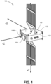
- Figure 1 illustrates a perspective view of an aircraft (e.g., a spacecraft) 100, according to an implementation.
- the spacecraft 100 is or includes a satellite that is configured to be placed into orbit around, for example, the Earth.
- the spacecraft 100 is able to move (e.g., rotate) around a first axis (e.g., an X axis). This movement is referred to as a roll of the spacecraft 100.
- the spacecraft 100 is also able to move (e.g., rotate) around a second axis (e.g., a Y axis). This movement is referred to as a pitch of the spacecraft 100.
- the spacecraft 100 is also able to move (e.g., rotate) around a third axis (e.g., a Z axis). This movement is referred to as a yaw of the spacecraft 100.
- the spacecraft 100 includes a transmitter antenna 110A and a receiver antenna 110B.
- the transmitter antenna 110A and the receiver antenna 110B are or include phase array antennas.
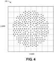
- the transmitter antenna 110A and the receiver antenna 110B may each include a plurality of phase array elements in a predefined pattern (as shown in Figure 4 ).
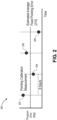
- FIG. 2 illustrates a graph 200 showing a pointing error (in degrees) of the transmitter antenna 110A versus time over the course of a single day.
- the spacecraft 100 may pass overhead of a gateway on Earth one or more times during the day. For example, the spacecraft 100 may pass over the gateway four times a day (e.g., every 6 hours).
- a "gateway" refers to a ground terminal that is configured to transmit signals to the spacecraft 100, receive signals from the spacecraft 100, and process the signals (e.g., using a computing system).
- a computing system 1400 that is used at the ground terminal is described below with reference to Figure 14 .
- the pointing error may be measured each time the spacecraft 100 passes over the gateway.
- Each set 202, 204, 206, 208 may include a plurality of measurements (e.g., 10 measurements).
- the sets of pointing error measurements 202, 204, 206, 208 may vary from time to time.
- the pointing error of the first set 202 is greater than the pointing error of the second set 204. This may be due to temperature variations throughout the day.
- an average fixed pointing error 210 may be determined based upon the pointing error measurement sets 202, 204, 206, 208.
- the average fixed pointing error 210 may at least partially remove fixed pointing error.
- Figure 3 illustrates a graph 300 showing a pointing error spatial simulation of the transmitter antenna 110A and the receiver antenna 110B.
- a first set of element locations 302 and a second set of locations 304 represent the location of phase array elements of the transmitter antenna 110A.
- the first set of element locations 302 is without pointing error
- the second set of element locations 304 includes the pointing error.
- a third set of element locations 306 and a fourth set of element locations 308 represent the location of phase array elements of the receiver antenna 110B.
- the third set of element locations 306 is without pointing error
- the fourth set of element locations 308 includes the pointing error.
- FIG. 4 illustrates a graph 400 of the element locations 302 looking downward along the Z-axis in the graph 300.
- each element location 302 represents the location of the phase array elements of the transmitter antenna 110A.
- the element locations 302 vary along the X-axis and the Y-axis and produce a phase measurement for each element.
- Figure 5 illustrates a flowchart of a method 500 for calibrating the transmitter antenna 110A of the spacecraft 100.
- the method 500 may be used to average-out diurnal-induced and/or temperature-induced alignment errors of the transmitter antenna 110A.
- the method includes receiving a plurality of signals from the transmitter antenna 110A, as at 502.
- the signals are generated by the phase array elements of the transmitter antenna 110A.
- the signals are received at the gateway on the ground.
- the signals are received by the computing system 1400 at the gateway, and the computing system 1400 measures the signals and/or determines how the transmitter antenna 110A should be calibrated based upon the signals, as described below.
- Each of the signals may be or include a tone at a different (e.g., unique) frequency.
- the method 500 also includes measuring or determining a phase tilt (also referred to as a phase slope) of the phase array elements of the transmitter antenna 110A based at least partially upon the signals (from 502), as at 504.
- the phase tilt may be measured by a vector spectrum analyzer (VSA), which may be a part of (or in communication with) the computing system 1400.
- VSA vector spectrum analyzer
- the "phase tilt” refers to a linear phase change versus distance.
- the method 500 also includes determining a location of the spacecraft 100 (e.g., in orbit), as at 506.
- the location may be measured by a location sensor (e.g., a global positioning system (GPS)) 120 on the spacecraft 100.
- the method 500 also includes determining an attitude of the spacecraft 100 (e.g., in orbit), as at 508.
- the attitude may be measured by an attitude sensor 122 on the spacecraft 100.
- the location and the attitude are transmitted from the spacecraft 100 to the computing system 1400 at the gateway, which makes the determinations (at 506 and 508).
- the location and/or the attitude are determined when the signals are generated (at 502) at the spacecraft 100 and/or received at the gateway.
- the phase tilt (measured at 504) may depend at least partially upon the location of the spacecraft (determined at 506), the attitude of the spacecraft 100 (measured at 508), and a misalignment error of the transmitter antenna 110A.
- the method 500 also includes removing a first portion of the phase tilt from the phase tilt measured at 504, as at 510.
- the first portion of the phase tilt is caused by the location and/or attitude of the spacecraft 100.
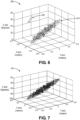
- Figure 6 illustrates a graph 600 of the phase tilt of the phase array elements of the transmitter antenna 110A with a physical delay variation caused by the array element pointing alignment error of the transmitter antenna 110 (e.g., physical misalignment) 610 and a digital delay variation caused by a digital signal processor (DSP) delay error 620, according to an implementation.
- Figure 6 includes both the physical and digital delay variations which create the outlier measurement values (i.e., DSP delay error 620).
- the DSP 124 that creates the DSP delay error 620 may be onboard the spacecraft 100 (see Figure 1 ).
- the method 500 may also include removing a second portion of the phase tilt from the phase tilt measured at 504, as at 512.
- the second portion of the phase tilt is caused by the DSP delay error 620.
- An example of this is shown in Figure 7 , which illustrates a graph 700 of the phase tilt of the phase array elements of the transmitter antenna 110A with the DSP delay error 620 (from Figure 6 ) removed, according to an implementation.
- Figure 7 is similar to Figure 3 , but focuses on the second set of measurements 304 (e.g., the location of the phase array elements of the transmitter antenna 110A with pointing error).
- Figure 7 only shows the error from physical misalignment.
- the DSP 124 has a plurality of discrete states, and each state has a different (e.g., unique) digital delay variation.
- the digital delay variation refers to discrete steps (e.g., at some fixed interval such as 60 picoseconds (ps), 120 ps, 180 ps, etc.) based on the DSP clock frequency.
- ps picoseconds
- the DSP 124 wakes up in one of the discrete states (e.g., randomly).
- the DSP 124 wakes up with a random discrete step digital delay variation that is caused by an analog-to-digital converter (ADC) and/or a digital-to-analog converter (DAC) and a sampling clock.
- ADC analog-to-digital converter
- DAC digital-to-analog converter
- the digital delay variation may be estimated and modified (e.g., corrected) through DSP delay buffers.
- the measurement by the computing system 1400 at the gateway of the phase across the transmitter antenna 110A may include both the physical delay variations and the digital delay variations.
- the modified (e.g., corrected) delay variation e.g., using initial estimates of the discrete delay offsets, modulus of the measured element delays, and DSP discrete delay step
- a user may determine whether the digital delay variation was over-estimated or underestimated. Once the phase array elements that are affected by the incorrect digital delay variations are identified, a final delay buffer setting may be determined.
- the method 500 also includes estimating the phase tilt of the phase array elements of the transmitter antenna 110A, as at 514.
- the phase tilt may be estimated after the first portion is removed (at 510) and/or the second portion is removed (at 512).
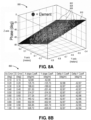
- An example of the estimated phase tilt is shown in Figure 8A , which illustrates a graph 800 showing the phase tilt (in degrees) versus the location of the phase array elements of the transmitter antenna 110A (in meters).
- the points (e.g., 802, 804, 806, etc.) on the graph 800 represent the phase measurement of the phase array elements.
- each point 802, 804, 806 represent the phase measurement of the phase array elements at a different pass over the gateway.
- the plane 810 represents a 2D polyfit of the phase tilt of the points 802, 804, 806.
- Figure 8B illustrates a table 850 showing the azimuth error (in degrees), the elevation error (in degrees), the X slope coefficient (in degrees per meter), the Y slope coefficient (in degrees per meter), the delta X coefficient (in degrees per meter), and the delta Y coefficient (in degrees per meter). These values are determined using the computing system 1400 based at least partially upon the estimated phase tilt of the phase array element elements of the transmitter antenna 110A (from 514).
- the foregoing portion of the method 500 (e.g., steps 502-514) is performed a first time using data/measurements from a first spacecraft location in orbit.
- the foregoing portion of the method 500 (e.g., steps 502-514) is then repeated in an iterative fashion one or more times using data/measurements from one or more different spacecraft locations in orbit.
- the steps 502-514 have been performed/repeated a second time at a second spacecraft location.
- the method 500 may also include generating a reference tilt matrix for the phase array elements of the transmitter antenna 110A at the first spacecraft location and the second spacecraft location, as at 516.
- the reference tilt matrix may be generated based at least partially upon the first and second spacecraft locations (from two iterations of 506), the first and second spacecraft attitudes (from two iterations of 508), and the gateway location (which is constant).
- generating the reference tilt matrix may include generating an expected phase tilt for a set of misalignment errors.
- Figure 9 illustrates a graph 900 of the reference tilt matrix for the phase array elements of the transmitter antenna 110A, according to an implementation.
- a first axis of the graph 900 represents a roll error (in degrees)
- a second axis of the graph 900 represents a pitch error (in degrees)
- a third axis of the graph 900 represents a yaw error (in degrees).
- the matrix is generated with an expected phase tilt at each 0.01 degree raster point.
- Four 3D matrices may be generated per array: one matrix at each of the two spacecraft locations, one matrix for the X slope, and one matrix for the Y slope.
- four measurements may be used to determine the three unknowns (e.g., roll, pitch, and yaw) per array.
- the method 500 also includes comparing the estimated phase tilt of the phase array elements of the transmitter antenna 110A (at 514) to the reference tilt matrix (at 516), as at 518.
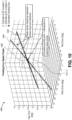
- Figure 10 illustrates a graph 1000 showing a phase tilt matrix correlation, according to an implementation. As shown, a first axis of the graph 1000 represents a roll error (in degrees), a second axis of the graph 1000 represents a pitch error (in degrees), and a third axis of the graph 1000 represents a yaw error (in degrees).
- the graph 1000 represents the phase tilt matrix correlation for a single measurement (e.g., one of the ten measurements).
- the graph 1000 includes a plurality of raster points that make up the set of misalignment errors 1002 and the set of misalignment errors 1004.
- the raster points match the measured phase tilt plus a tolerance.
- the set of misalignment errors 1002 represents a first estimate of the location of the spacecraft 100
- the set of misalignment errors 1104 represents a second estimate of the location of the spacecraft 100.
- the intersection 1006 represents the estimated pointing error.
- the method 500 also includes determining an intersection 1006 of first set of misalignment errors 1002 and the second set of misalignment errors 1004, as at 520.
- a plurality of measurements e.g., 10 measurements
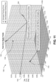
- FIG 11 illustrates a graph 1100 that represents an enlarged portion of the graph 1000, according to an implementation.
- a first axis of the graph 1100 represents a roll error (in degrees)
- a second axis of the graph 1100 represents a pitch error (in degrees)
- a third axis of the graph 1100 represents a yaw error (in degrees).
- the graph 1100 shows the estimated pointing errors for 10 measurements.
- the graph 1100 shows estimated pointing errors.
- the graph 1100 includes a plurality of intersections 1102, 1104, 1106, 1108, etc. that represent estimated pointing errors.
- the graph 1100 also shows and a final estimated pointing error 1110.
- the final estimated pointing error 1110 may be determined by filtering and/or averaging the estimated pointing errors 1102, 1104, 1106, 1108, etc.
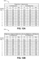
- Figure 12A illustrates a table 1200 showing the pointing error of the transmitter antenna 110A and the pointing error of the receiver antenna 110B with a phase measurement error of 2 degrees root-mean-square (RMS) only, according to an implementation.
- the pointing error may include an elevation error, an azimuth error, and a yaw error.
- the values in the table 1200 may be determined during a plurality of iterations (e.g., ten) with a phase measurement error of, for example, 2 degrees root-mean-square only. Each iteration has a different fixed pointing error and spacecraft longitude. Within each iteration, a plurality (e.g., ten) measurements may be performed with random phase error on each phase array element.
- the top row represents the iteration maximum, which refers to the maximum residual pointing error of the simulation iterations.
- the maximum residual pointing error is below an illustrative pointing error target/goal, which, in this example, is 0.04 degrees elevation, 0.04 degrees azimuth, and 0.06 degrees yaw.
- Figure 12B illustrates a table 1250 showing the pointing error of the transmitter antenna 110A and the pointing error of the receiver antenna 110B with a phase measurement error of 6 degrees RMS, a position knowledge error of 50 meters RMS, and an attitude knowledge error of 0.005 degrees RMS, according to an implementation.
- the pointing error may include an elevation error, an azimuth error, and a yaw error.
- the values in the table 1250 may be determined during a plurality of iterations (e.g., ten). Each iteration has a different fixed pointing error, spacecraft longitude, and spacecraft telemetry error (e.g., location and attitude). Within each iteration, a plurality (e.g., ten) measurements are performed with random phase error on each element.
- the top row represents the iteration maximum. As may be seen in the table 1250, the maximum residual pointing error is below the pointing error target/goal, which, in this example, is 0.04 degrees elevation, 0.04 degrees azimuth, and 0.06 degrees yaw.
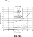
- Figure 13A illustrates a graph 1300 showing the residual pointing error (in degrees) versus gateway latitude (in degrees) for the transmitter antenna 110A, according to an implementation.
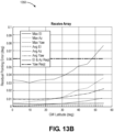
- Figure 13B illustrates a graph 1350 showing the residual pointing error (in degrees) versus gateway latitude (in degrees) for the receiver antenna 110B, according to an implementation.
- a parametric sweep of the gateway latitude was run from 0 degrees to 55 degrees in steps of 5 degrees. There were 100 iterations per step.
- a first spacecraft longitude offset was maintained at a random value between 7 degrees and 12 degrees
- a second spacecraft longitude offset was maintained at a random value between -7 degrees and -12 degrees.
- the residual pointing error target/goals e.g., 0.04 degrees elevation, 0.04 degrees azimuth, and 0.06 degrees yaw
- the target/goal may be achieved for a wide variety of gateway latitude locations.
- the method 500 may also include transmitting a signal from the computing system 1400 at the gateway to the spacecraft 100 that causes the spacecraft 100 to move to reduce the pointing error, as at 522.
- the signal may cause the spacecraft 100 to physically roll, pitch, and/or yaw to reduce the pointing error.
- the signal may be received by the DSP 124 on the spacecraft 100, and the DSP 124 may then re-point the phase array elements electronically (e.g., not physically) to adjust for (reduce) the pointing error.
- the signal may be based upon the intersection(s) at 520.
- the gateway location has a latitude of 21.66 degrees and a longitude of -158.05 degrees.
- the spacecraft longitude offset 1 is random between 7 degrees and 12 degrees
- the spacecraft longitude offset 2 is random between -7 degrees and -12 degrees.
- the yaw rotation is 0.36 degree per degree of longitude.
- the phase measurements are performed using the same portion of the method 500 described above.
- the simulated measurement phase variation is 2 degrees RMS.
- the simulation was also run with 6 degrees RMS.
- the transmitter frequency was 18.95 GHz, and the receiver frequency was 28.75 GHz.
- Ten measurements were taken at each spacecraft location. As described above, this may be repeated multiple (e.g., 4) times throughout the day at various drive levels to average out diurnal and/or temperature errors.
- the spacecraft state vector telemetry may provide spacecraft location and attitude, which may be used to compensate the measurements.
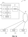
- FIG. 14 illustrates a schematic view of a computing system 1400 for performing at least a portion of the method 500.
- the computing system 1400 includes a computer or computer system 1401A, which may be an individual computer system 1401A or an arrangement of distributed computer systems.
- the computer system 1401A includes one or more analysis modules 1402 that are configured to perform various tasks according to some implementations, such as one or more methods disclosed herein. To perform these various tasks, the analysis module 1402 executes independently, or in coordination with, one or more processors 1404, which is (or are) connected to one or more storage media 1406.
- the processor(s) 1404 is (or are) also connected to a network interface 1407 to allow the computer system 1401A to communicate over a data network 1409 with one or more additional computer systems and/or computing systems, such as 1401B, 1401C, and/or 1401D (note that computer systems 1401B, 1401C and/or 1401D may or may not share the same architecture as computer system 1401A, and may be located in different physical locations, e.g., computer systems 1401A and 1401B may be located in a processing facility, while in communication with one or more computer systems such as 1401C and/or 1401D that are located in one or more data centers, and/or located in varying countries on different continents).
- a processor may include a microprocessor, microcontroller, processor module or subsystem, programmable integrated circuit, programmable gate array, or another control or computing device.
- the storage media 1406 may be implemented as one or more computer-readable or machine-readable storage media. Note that while in the example implementation of Figure 14 storage media 1406 is depicted as within computer system 1401A, in some implementations, storage media 1406 may be distributed within and/or across multiple internal and/or external enclosures of computing system 1401A and/or additional computing systems.
- Storage media 1406 may include one or more different forms of memory including semiconductor memory devices such as dynamic or static random access memories (DRAMs or SRAMs), erasable and programmable read-only memories (EPROMs), electrically erasable and programmable read-only memories (EEPROMs) and flash memories, magnetic disks such as fixed, floppy and removable disks, other magnetic media including tape, optical media such as compact disks (CDs) or digital video disks (DVDs), BLURAY ® disks, or other types of optical storage, or other types of storage devices.
- semiconductor memory devices such as dynamic or static random access memories (DRAMs or SRAMs), erasable and programmable read-only memories (EPROMs), electrically erasable and programmable read-only memories (EEPROMs) and flash memories
- magnetic disks such as fixed, floppy and removable disks, other magnetic media including tape
- optical media such as compact disks (CDs) or digital video disks (DVDs)
- DVDs digital video disks
- Such computer-readable or machine-readable storage medium or media is (are) considered to be part of an article (or article of manufacture).
- An article or article of manufacture may refer to any manufactured single component or multiple components.
- the storage medium or media may be located either in the machine running the machine-readable instructions, or located at a remote site from which machine-readable instructions may be downloaded over a network for execution.
- Computing system 1400 contains one or more antenna calibration module(s) 1408 that perform at least a portion of the method 500 disclosed herein. It should be appreciated that computing system 1400 is merely one example of a computing system, and that computing system 1400 may have more or fewer components than shown, may combine additional components not depicted in the example implementation of Figure 14 , and/or computing system 1400 may have a different configuration or arrangement of the components depicted in Figure 14 .
- the various components shown in Figure 14 may be implemented in hardware, software, or a combination of both hardware and software, including one or more signal processing and/or application specific integrated circuits.
- steps in the processing methods described herein may be implemented by running one or more functional modules in information processing apparatus such as general purpose processors or application specific chips, such as ASICs, FPGAs, PLDs, or other appropriate devices.
- ASICs general purpose processors or application specific chips, such as ASICs, FPGAs, PLDs, or other appropriate devices.
- Computational interpretations, models, and/or other interpretation aids may be refined in an iterative fashion; this concept is applicable to the methods discussed herein. This may include use of feedback loops executed on an algorithmic basis, such as at a computing device (e.g., computing system 1400, Figure 14 ), and/or through manual control by a user who may make determinations regarding whether a given step, action, template, model, or set of curves has become sufficiently accurate for the evaluation of the subsurface three-dimensional geologic formation under consideration.
- a computing device e.g., computing system 1400, Figure 14
Landscapes
- Engineering & Computer Science (AREA)
- Physics & Mathematics (AREA)
- Astronomy & Astrophysics (AREA)
- General Physics & Mathematics (AREA)
- Aviation & Aerospace Engineering (AREA)
- Computer Networks & Wireless Communication (AREA)
- Signal Processing (AREA)
- Remote Sensing (AREA)
- Electromagnetism (AREA)
- Variable-Direction Aerials And Aerial Arrays (AREA)
- Radar Systems Or Details Thereof (AREA)
Claims (15)
- Verfahren (500), das durch ein Computersystem (1400) an einem Gateway auf dem Boden zum Kalibrieren einer auf einem Raumfahrzeug (100) angeordneten Antenne (110A) implementiert ist, aufweisend:Empfangen einer Vielzahl von Signalen, die von der Antenne (10A) übertragen werden, wobei die Antenne (110A) eine Vielzahl von Phasenanordnungselementen aufweist;Bestimmen einer Phasenneigung der Phasenanordnungselemente zumindest teilweise basierend auf den Signalen;Bestimmen eines ersten Orts des Raumfahrzeugs (100), einer ersten Lage des Raumfahrzeugs (100), oder beides;Entfernen eines ersten Abschnitts aus der bestimmten Phasenneigung, wobei der erste Abschnitt durch den ersten Ort des Raumfahrzeugs (100), die erste Lage des Raumfahrzeugs (100) oder beides verursacht wird;Schätzen der Phasenneigung der Phasenanordnungselemente, nachdem der erste Abschnitt entfernt wurde;Erzeugen einer Referenzneigungsmatrix für die Phasenanordnungselemente;Vergleichen der geschätzten Phasenneigung mit der Referenzneigungsmatrix; undBestimmen eines Ausrichtungsfehlers der Antenne (110A) zumindest teilweise basierend auf dem Vergleich.
- Verfahren nach Anspruch 1, wobei jedes der Signale einen Ton mit einer unterschiedlichen Frequenz aufweist.
- Verfahren nach Anspruch 1 oder 2, wobei der erste Ort des Raumfahrzeugs (100), die erste Lage des Raumfahrzeugs (100) oder beide von einem oder mehreren Sensoren an Bord des Raumfahrzeugs (100) gemessen und an ein Computersystem (1400) an einem Gateway auf dem Boden übertragen werden.
- Verfahren nach einem der Ansprüche 1-3, wobei der erste Abschnitt entfernt wird, um einen Ausrichtungsfehler (1002, 1004) der Antenne zu isolieren.
- Verfahren nach einem der Ansprüche 1-4, des Weiteren aufweisend das Entfernen eines zweiten Abschnitts aus der bestimmten Phasenneigung, die durch einen Verzögerungsfehler eines Prozessors (124) auf dem Raumfahrzeug (100) verursacht wird, wobei die Phasenneigung geschätzt wird, nachdem der erste Abschnitt und der zweite Abschnitt entfernt wurden.
- Verfahren nach einem der Ansprüche 1-5, wobei die Referenz-Neigungsmatrix zumindest teilweise auf der Grundlage eines ersten Orts des Raumfahrzeugs (100) und eines zweiten Orts des Raumfahrzeugs (100) erzeugt wird, wobei der zweite Ort des Raumfahrzeugs (100) nach dem ersten Ort des Raumfahrzeugs (100) auftritt.
- Verfahren nach Anspruch 6, wobei das Vergleichen der geschätzten Phasenneigung mit der Referenz-Neigungsmatrix einen ersten Satz von Ausrichtungsfehlern (1002) erzeugt, der mit der der geschätzten Phasenneigung für den ersten Ort übereinstimmt, und einen zweiten Satz von Ausrichtungsfehlern (1004), der mit der geschätzten Phasenneigung für den zweiten Ort übereinstimmt.
- Verfahren nach Anspruch 7, wobei das Bestimmen des Ausrichtungsfehlers der Antenne (110A) das Bestimmen eines Schnittpunkts (1006) des ersten Satzes von Ausrichtungsfehlern und des zweiten Satzes von Ausrichtungsfehlern aufweist.
- Verfahren nach einem der Ansprüche 1-8, des Weiteren aufweisend das Kalibrieren der Antenne (110A), um den Ausrichtungsfehler zu reduzieren.
- Verfahren nach Anspruch 9, wobei das Kalibrieren der Antenne (110A) das Bewirken aufweist, dass das Raumfahrzeug (100) physikalisch oder elektronisch rollt, nickt, giert oder eine Kombination davon.
- Computersystem (1400) an einem Gateway auf dem Boden, das aufweist:einen oder mehrere Prozessoren (1404); undein Speichersystem, das ein oder mehrere nicht-flüchtige computerlesbare Medien aufweist, die Befehle speichern, die, wenn sie von mindestens einem der ein oder mehreren Prozessoren ausgeführt werden, das Computersystem veranlassen, Vorgänge auszuführen, wobei die Vorgänge aufweisen:Empfangen einer Mehrzahl von Signalen, die von einer an einem Raumfahrzeug angeordneten Antenne (110A) empfangen werden, wobei die Antenne (110A) eine Mehrzahl von Phasenanordnungselementen aufweist;Bestimmen einer Phasenneigung der Phasenanordnungselemente basierend zumindest teilweise auf den Signalen;Bestimmen eines ersten Orts des Raumfahrzeugs (100), einer ersten Lage des Raumfahrzeugs (100) oder beides;Entfernen eines ersten Abschnitts aus der bestimmten Phasenneigung, wobei der erste Abschnitt durch den ersten Ort des Raumfahrzeugs (100), die erste Lage des Raumfahrzeugs (100) oder beides verursacht wird;Schätzen der Phasenneigung der Phasenanordnungselemente, nachdem der erste Abschnitt entfernt wurde;Erzeugen einer Referenzneigungsmatrix für die Phasenanordnungselemente;Vergleichen der geschätzten Phasenneigung mit der Referenzneigungsmatrix; undBestimmen eines Ausrichtungsfehlers der Antenne (110A) basierend zumindest teilweise auf dem Vergleich.
- Computersystem nach Anspruch 11, wobei die Vorgänge des Weiteren aufweisen das Entfernen eines zweiten Abschnitts aus der bestimmten Phasenneigung, der durch einen Verzögerungsfehler eines Prozessors auf dem Raumfahrzeug (100) verursacht wird, und wobei die Phasenneigung der Phasenanordnungselemente geschätzt wird, nachdem der erste Abschnitt und der zweite Abschnitt entfernt worden sind.
- Computersystem nach Anspruch 11, wobei die Referenzneigungsmatrix zumindest teilweise basierend auf dem ersten Ort des Raumfahrzeugs (100) und einem zweiten Ort des Raumfahrzeugs (100) erzeugt wird, wobei der zweite Ort des Raumfahrzeugs (100) nach dem ersten Ort des Raumfahrzeugs (100) auftritt.
- Computersystem nach Anspruch 13, wobei der Vergleich der geschätzten Phasenneigung mit der Referenzverschiebungsmatrix einen ersten Satz von Ausrichtungsfehlern (1002) erzeugt, die mit der geschätzten Phasenverschiebung für den ersten Ort übereinstimmen, und einen zweiten Satz von Ausrichtungsfehlern (1004), die mit der geschätzten Phasenneigung für den zweiten Ort übereinstimmen.
- Computersystem nach Anspruch 14, wobei das Bestimmen des Ausrichtungsfehlers der der Antenne (110A) das Bestimmen eines Schnittpunkts (1006) aus dem ersten Satz von Ausrichtungsfehlern und dem zweiten Satz von Ausrichtungsfehlern aufweist.
Applications Claiming Priority (1)
| Application Number | Priority Date | Filing Date | Title |
|---|---|---|---|
| US16/734,939 US20210210841A1 (en) | 2020-01-06 | 2020-01-06 | System and method for calibrating an antenna |
Publications (2)
| Publication Number | Publication Date |
|---|---|
| EP3846358A1 EP3846358A1 (de) | 2021-07-07 |
| EP3846358B1 true EP3846358B1 (de) | 2023-09-06 |
Family
ID=73855691
Family Applications (1)
| Application Number | Title | Priority Date | Filing Date |
|---|---|---|---|
| EP20215317.7A Active EP3846358B1 (de) | 2020-01-06 | 2020-12-18 | System und verfahren zur kalibrierung einer antenne |
Country Status (3)
| Country | Link |
|---|---|
| US (1) | US20210210841A1 (de) |
| EP (1) | EP3846358B1 (de) |
| CN (1) | CN113078968B (de) |
Families Citing this family (2)
| Publication number | Priority date | Publication date | Assignee | Title |
|---|---|---|---|---|
| JP7653928B2 (ja) | 2022-01-19 | 2025-03-31 | 三菱電機株式会社 | 情報処理装置、情報処理方法及び情報処理プログラム |
| CN120342513B (zh) * | 2025-06-18 | 2025-09-09 | 成都玖锦科技有限公司 | 一种基于无人机的相控阵通道相位高精度测量方法及系统 |
Family Cites Families (7)
| Publication number | Priority date | Publication date | Assignee | Title |
|---|---|---|---|---|
| EP2074711A2 (de) * | 2006-10-06 | 2009-07-01 | ViaSat, Inc. | Vorwärts- und rückwärtskalibration für bodengestützte strahlformung |
| GB2517218B (en) * | 2013-08-16 | 2017-10-04 | Analog Devices Global | Communication unit and method of antenna array calibration |
| US9853715B2 (en) * | 2014-02-17 | 2017-12-26 | Ubiqomm Llc | Broadband access system via drone/UAV platforms |
| US9608716B1 (en) * | 2016-04-06 | 2017-03-28 | Space Systems/Loral, Llc | Satellite transmit antenna ground-based pointing |
| US9642107B1 (en) * | 2016-08-01 | 2017-05-02 | Space Systems/Loral, Inc. | Multi-channel satellite calibration |
| US9900112B1 (en) * | 2017-03-03 | 2018-02-20 | Futurewei Technologies, Inc. | Method for calibration of a MIMO array based on an opportunistic signal |
| US10921427B2 (en) * | 2018-02-21 | 2021-02-16 | Leolabs, Inc. | Drone-based calibration of a phased array radar |
-
2020
- 2020-01-06 US US16/734,939 patent/US20210210841A1/en not_active Abandoned
- 2020-12-18 EP EP20215317.7A patent/EP3846358B1/de active Active
-
2021
- 2021-01-06 CN CN202110011416.3A patent/CN113078968B/zh active Active
Also Published As
| Publication number | Publication date |
|---|---|
| CN113078968A (zh) | 2021-07-06 |
| US20210210841A1 (en) | 2021-07-08 |
| CN113078968B (zh) | 2025-11-14 |
| EP3846358A1 (de) | 2021-07-07 |
Similar Documents
| Publication | Publication Date | Title |
|---|---|---|
| EP2449626B1 (de) | Selbstkalibrierende konforme phasengesteuerte gruppenantenne | |
| US10571544B2 (en) | Direction finding using signal power | |
| EP2824479B1 (de) | Verfahren und System zum Orten eines sich bewegenden Fahrzeugs | |
| Umeyama et al. | UAV-based far-field antenna pattern measurement method for polarimetric weather radars: Simulation and error analysis | |
| AU2021360236A1 (en) | Antenna evaluation test system | |
| US8294610B2 (en) | Systems and methods for resolving interferometric angle-of-arrival ambiguities due to local multipath reflections | |
| CN101371158B (zh) | 通过功率测量控制一组编队飞行器中飞行器的相对位置的设备 | |
| EP1828803A1 (de) | System und verfahren zur kalibrierung von radar-arrays | |
| US6806837B1 (en) | Deep depression angle calibration of airborne direction finding arrays | |
| CN102753991A (zh) | 短基线和超短基线相位图 | |
| EP3846358B1 (de) | System und verfahren zur kalibrierung einer antenne | |
| Culotta-López et al. | On the uncertainty sources of drone-based outdoor far-field antenna measurements | |
| CN119620130B (zh) | 一种雷达干涉仪定位体制相位优化方法 | |
| Leppinen et al. | The Aalto-1 nanosatellite navigation subsystem: Development results and planned operations | |
| Srinivas et al. | Conformal multi-service antenna arrays: Hybrid in situ & signal of opportunity (SoOP) calibration | |
| CN112859053A (zh) | 一种标定激光雷达时变参数的方法及系统 | |
| Arnold et al. | Effects of vibration on a wing-mounted ice-sounding antenna array | |
| Martin et al. | Large reflector uplink arraying | |
| Culotta-López et al. | On gain measurements using the substitution method with UASs | |
| Klassen et al. | Development of hardware and software complex for measurement of direction patterns of large aperture antennas with the use of unmanned aerial vehicle and GLONASS system | |
| US11994602B2 (en) | Method for calibrating an airborne goniometry apparatus for low frequencies | |
| Wang et al. | Single-antenna attitude determination for Fedsat with improved antenna gain patterns | |
| Schovaers et al. | Calibration of SKA-low antenna array using drones | |
| Schoenbrod et al. | Calibrating Reception Characteristics of Antenna Elements and RF-Frontend Within a Phased Array Using Machine Learning Techniques | |
| Dmitriev et al. | Methods beamforming adaptive digital array and their study using a computer model |
Legal Events
| Date | Code | Title | Description |
|---|---|---|---|
| PUAI | Public reference made under article 153(3) epc to a published international application that has entered the european phase |
Free format text: ORIGINAL CODE: 0009012 |
|
| STAA | Information on the status of an ep patent application or granted ep patent |
Free format text: STATUS: THE APPLICATION HAS BEEN PUBLISHED |
|
| AK | Designated contracting states |
Kind code of ref document: A1 Designated state(s): AL AT BE BG CH CY CZ DE DK EE ES FI FR GB GR HR HU IE IS IT LI LT LU LV MC MK MT NL NO PL PT RO RS SE SI SK SM TR |
|
| STAA | Information on the status of an ep patent application or granted ep patent |
Free format text: STATUS: REQUEST FOR EXAMINATION WAS MADE |
|
| 17P | Request for examination filed |
Effective date: 20211116 |
|
| RBV | Designated contracting states (corrected) |
Designated state(s): AL AT BE BG CH CY CZ DE DK EE ES FI FR GB GR HR HU IE IS IT LI LT LU LV MC MK MT NL NO PL PT RO RS SE SI SK SM TR |
|
| RAP3 | Party data changed (applicant data changed or rights of an application transferred) |
Owner name: THE BOEING COMPANY |
|
| GRAP | Despatch of communication of intention to grant a patent |
Free format text: ORIGINAL CODE: EPIDOSNIGR1 |
|
| STAA | Information on the status of an ep patent application or granted ep patent |
Free format text: STATUS: GRANT OF PATENT IS INTENDED |
|
| INTG | Intention to grant announced |
Effective date: 20230329 |
|
| GRAS | Grant fee paid |
Free format text: ORIGINAL CODE: EPIDOSNIGR3 |
|
| GRAA | (expected) grant |
Free format text: ORIGINAL CODE: 0009210 |
|
| STAA | Information on the status of an ep patent application or granted ep patent |
Free format text: STATUS: THE PATENT HAS BEEN GRANTED |
|
| AK | Designated contracting states |
Kind code of ref document: B1 Designated state(s): AL AT BE BG CH CY CZ DE DK EE ES FI FR GB GR HR HU IE IS IT LI LT LU LV MC MK MT NL NO PL PT RO RS SE SI SK SM TR |
|
| P01 | Opt-out of the competence of the unified patent court (upc) registered |
Effective date: 20230731 |
|
| REG | Reference to a national code |
Ref country code: GB Ref legal event code: FG4D |
|
| REG | Reference to a national code |
Ref country code: CH Ref legal event code: EP |
|
| REG | Reference to a national code |
Ref country code: IE Ref legal event code: FG4D |
|
| REG | Reference to a national code |
Ref country code: DE Ref legal event code: R096 Ref document number: 602020017162 Country of ref document: DE |
|
| REG | Reference to a national code |
Ref country code: LT Ref legal event code: MG9D |
|
| REG | Reference to a national code |
Ref country code: NL Ref legal event code: MP Effective date: 20230906 |
|
| PG25 | Lapsed in a contracting state [announced via postgrant information from national office to epo] |
Ref country code: GR Free format text: LAPSE BECAUSE OF FAILURE TO SUBMIT A TRANSLATION OF THE DESCRIPTION OR TO PAY THE FEE WITHIN THE PRESCRIBED TIME-LIMIT Effective date: 20231207 |
|
| PG25 | Lapsed in a contracting state [announced via postgrant information from national office to epo] |
Ref country code: SE Free format text: LAPSE BECAUSE OF FAILURE TO SUBMIT A TRANSLATION OF THE DESCRIPTION OR TO PAY THE FEE WITHIN THE PRESCRIBED TIME-LIMIT Effective date: 20230906 Ref country code: RS Free format text: LAPSE BECAUSE OF FAILURE TO SUBMIT A TRANSLATION OF THE DESCRIPTION OR TO PAY THE FEE WITHIN THE PRESCRIBED TIME-LIMIT Effective date: 20230906 Ref country code: NO Free format text: LAPSE BECAUSE OF FAILURE TO SUBMIT A TRANSLATION OF THE DESCRIPTION OR TO PAY THE FEE WITHIN THE PRESCRIBED TIME-LIMIT Effective date: 20231206 Ref country code: LV Free format text: LAPSE BECAUSE OF FAILURE TO SUBMIT A TRANSLATION OF THE DESCRIPTION OR TO PAY THE FEE WITHIN THE PRESCRIBED TIME-LIMIT Effective date: 20230906 Ref country code: LT Free format text: LAPSE BECAUSE OF FAILURE TO SUBMIT A TRANSLATION OF THE DESCRIPTION OR TO PAY THE FEE WITHIN THE PRESCRIBED TIME-LIMIT Effective date: 20230906 Ref country code: HR Free format text: LAPSE BECAUSE OF FAILURE TO SUBMIT A TRANSLATION OF THE DESCRIPTION OR TO PAY THE FEE WITHIN THE PRESCRIBED TIME-LIMIT Effective date: 20230906 Ref country code: GR Free format text: LAPSE BECAUSE OF FAILURE TO SUBMIT A TRANSLATION OF THE DESCRIPTION OR TO PAY THE FEE WITHIN THE PRESCRIBED TIME-LIMIT Effective date: 20231207 Ref country code: FI Free format text: LAPSE BECAUSE OF FAILURE TO SUBMIT A TRANSLATION OF THE DESCRIPTION OR TO PAY THE FEE WITHIN THE PRESCRIBED TIME-LIMIT Effective date: 20230906 |
|
| REG | Reference to a national code |
Ref country code: AT Ref legal event code: MK05 Ref document number: 1609894 Country of ref document: AT Kind code of ref document: T Effective date: 20230906 |
|
| PG25 | Lapsed in a contracting state [announced via postgrant information from national office to epo] |
Ref country code: NL Free format text: LAPSE BECAUSE OF FAILURE TO SUBMIT A TRANSLATION OF THE DESCRIPTION OR TO PAY THE FEE WITHIN THE PRESCRIBED TIME-LIMIT Effective date: 20230906 |
|
| PG25 | Lapsed in a contracting state [announced via postgrant information from national office to epo] |
Ref country code: IS Free format text: LAPSE BECAUSE OF FAILURE TO SUBMIT A TRANSLATION OF THE DESCRIPTION OR TO PAY THE FEE WITHIN THE PRESCRIBED TIME-LIMIT Effective date: 20240106 |
|
| PG25 | Lapsed in a contracting state [announced via postgrant information from national office to epo] |
Ref country code: AT Free format text: LAPSE BECAUSE OF FAILURE TO SUBMIT A TRANSLATION OF THE DESCRIPTION OR TO PAY THE FEE WITHIN THE PRESCRIBED TIME-LIMIT Effective date: 20230906 |
|
| PG25 | Lapsed in a contracting state [announced via postgrant information from national office to epo] |
Ref country code: ES Free format text: LAPSE BECAUSE OF FAILURE TO SUBMIT A TRANSLATION OF THE DESCRIPTION OR TO PAY THE FEE WITHIN THE PRESCRIBED TIME-LIMIT Effective date: 20230906 |
|
| PG25 | Lapsed in a contracting state [announced via postgrant information from national office to epo] |
Ref country code: SM Free format text: LAPSE BECAUSE OF FAILURE TO SUBMIT A TRANSLATION OF THE DESCRIPTION OR TO PAY THE FEE WITHIN THE PRESCRIBED TIME-LIMIT Effective date: 20230906 Ref country code: RO Free format text: LAPSE BECAUSE OF FAILURE TO SUBMIT A TRANSLATION OF THE DESCRIPTION OR TO PAY THE FEE WITHIN THE PRESCRIBED TIME-LIMIT Effective date: 20230906 Ref country code: IS Free format text: LAPSE BECAUSE OF FAILURE TO SUBMIT A TRANSLATION OF THE DESCRIPTION OR TO PAY THE FEE WITHIN THE PRESCRIBED TIME-LIMIT Effective date: 20240106 Ref country code: ES Free format text: LAPSE BECAUSE OF FAILURE TO SUBMIT A TRANSLATION OF THE DESCRIPTION OR TO PAY THE FEE WITHIN THE PRESCRIBED TIME-LIMIT Effective date: 20230906 Ref country code: EE Free format text: LAPSE BECAUSE OF FAILURE TO SUBMIT A TRANSLATION OF THE DESCRIPTION OR TO PAY THE FEE WITHIN THE PRESCRIBED TIME-LIMIT Effective date: 20230906 Ref country code: CZ Free format text: LAPSE BECAUSE OF FAILURE TO SUBMIT A TRANSLATION OF THE DESCRIPTION OR TO PAY THE FEE WITHIN THE PRESCRIBED TIME-LIMIT Effective date: 20230906 Ref country code: AT Free format text: LAPSE BECAUSE OF FAILURE TO SUBMIT A TRANSLATION OF THE DESCRIPTION OR TO PAY THE FEE WITHIN THE PRESCRIBED TIME-LIMIT Effective date: 20230906 Ref country code: SK Free format text: LAPSE BECAUSE OF FAILURE TO SUBMIT A TRANSLATION OF THE DESCRIPTION OR TO PAY THE FEE WITHIN THE PRESCRIBED TIME-LIMIT Effective date: 20230906 Ref country code: PT Free format text: LAPSE BECAUSE OF FAILURE TO SUBMIT A TRANSLATION OF THE DESCRIPTION OR TO PAY THE FEE WITHIN THE PRESCRIBED TIME-LIMIT Effective date: 20240108 |
|
| PG25 | Lapsed in a contracting state [announced via postgrant information from national office to epo] |
Ref country code: PL Free format text: LAPSE BECAUSE OF FAILURE TO SUBMIT A TRANSLATION OF THE DESCRIPTION OR TO PAY THE FEE WITHIN THE PRESCRIBED TIME-LIMIT Effective date: 20230906 Ref country code: IT Free format text: LAPSE BECAUSE OF FAILURE TO SUBMIT A TRANSLATION OF THE DESCRIPTION OR TO PAY THE FEE WITHIN THE PRESCRIBED TIME-LIMIT Effective date: 20230906 |
|
| REG | Reference to a national code |
Ref country code: DE Ref legal event code: R097 Ref document number: 602020017162 Country of ref document: DE |
|
| PG25 | Lapsed in a contracting state [announced via postgrant information from national office to epo] |
Ref country code: DK Free format text: LAPSE BECAUSE OF FAILURE TO SUBMIT A TRANSLATION OF THE DESCRIPTION OR TO PAY THE FEE WITHIN THE PRESCRIBED TIME-LIMIT Effective date: 20230906 |
|
| PLBE | No opposition filed within time limit |
Free format text: ORIGINAL CODE: 0009261 |
|
| STAA | Information on the status of an ep patent application or granted ep patent |
Free format text: STATUS: NO OPPOSITION FILED WITHIN TIME LIMIT |
|
| PG25 | Lapsed in a contracting state [announced via postgrant information from national office to epo] |
Ref country code: DK Free format text: LAPSE BECAUSE OF FAILURE TO SUBMIT A TRANSLATION OF THE DESCRIPTION OR TO PAY THE FEE WITHIN THE PRESCRIBED TIME-LIMIT Effective date: 20230906 Ref country code: SI Free format text: LAPSE BECAUSE OF FAILURE TO SUBMIT A TRANSLATION OF THE DESCRIPTION OR TO PAY THE FEE WITHIN THE PRESCRIBED TIME-LIMIT Effective date: 20230906 |
|
| REG | Reference to a national code |
Ref country code: CH Ref legal event code: PL |
|
| 26N | No opposition filed |
Effective date: 20240607 |
|
| PG25 | Lapsed in a contracting state [announced via postgrant information from national office to epo] |
Ref country code: LU Free format text: LAPSE BECAUSE OF NON-PAYMENT OF DUE FEES Effective date: 20231218 |
|
| PG25 | Lapsed in a contracting state [announced via postgrant information from national office to epo] |
Ref country code: MC Free format text: LAPSE BECAUSE OF FAILURE TO SUBMIT A TRANSLATION OF THE DESCRIPTION OR TO PAY THE FEE WITHIN THE PRESCRIBED TIME-LIMIT Effective date: 20230906 |
|
| REG | Reference to a national code |
Ref country code: BE Ref legal event code: MM Effective date: 20231231 |
|
| PG25 | Lapsed in a contracting state [announced via postgrant information from national office to epo] |
Ref country code: MC Free format text: LAPSE BECAUSE OF FAILURE TO SUBMIT A TRANSLATION OF THE DESCRIPTION OR TO PAY THE FEE WITHIN THE PRESCRIBED TIME-LIMIT Effective date: 20230906 Ref country code: LU Free format text: LAPSE BECAUSE OF NON-PAYMENT OF DUE FEES Effective date: 20231218 |
|
| REG | Reference to a national code |
Ref country code: IE Ref legal event code: MM4A |
|
| PG25 | Lapsed in a contracting state [announced via postgrant information from national office to epo] |
Ref country code: IE Free format text: LAPSE BECAUSE OF NON-PAYMENT OF DUE FEES Effective date: 20231218 |
|
| PG25 | Lapsed in a contracting state [announced via postgrant information from national office to epo] |
Ref country code: BE Free format text: LAPSE BECAUSE OF NON-PAYMENT OF DUE FEES Effective date: 20231231 |
|
| PG25 | Lapsed in a contracting state [announced via postgrant information from national office to epo] |
Ref country code: CH Free format text: LAPSE BECAUSE OF NON-PAYMENT OF DUE FEES Effective date: 20231231 |
|
| PG25 | Lapsed in a contracting state [announced via postgrant information from national office to epo] |
Ref country code: IE Free format text: LAPSE BECAUSE OF NON-PAYMENT OF DUE FEES Effective date: 20231218 Ref country code: CH Free format text: LAPSE BECAUSE OF NON-PAYMENT OF DUE FEES Effective date: 20231231 Ref country code: BE Free format text: LAPSE BECAUSE OF NON-PAYMENT OF DUE FEES Effective date: 20231231 |
|
| PG25 | Lapsed in a contracting state [announced via postgrant information from national office to epo] |
Ref country code: BG Free format text: LAPSE BECAUSE OF FAILURE TO SUBMIT A TRANSLATION OF THE DESCRIPTION OR TO PAY THE FEE WITHIN THE PRESCRIBED TIME-LIMIT Effective date: 20230906 |
|
| PG25 | Lapsed in a contracting state [announced via postgrant information from national office to epo] |
Ref country code: BG Free format text: LAPSE BECAUSE OF FAILURE TO SUBMIT A TRANSLATION OF THE DESCRIPTION OR TO PAY THE FEE WITHIN THE PRESCRIBED TIME-LIMIT Effective date: 20230906 |
|
| PG25 | Lapsed in a contracting state [announced via postgrant information from national office to epo] |
Ref country code: CY Free format text: LAPSE BECAUSE OF FAILURE TO SUBMIT A TRANSLATION OF THE DESCRIPTION OR TO PAY THE FEE WITHIN THE PRESCRIBED TIME-LIMIT; INVALID AB INITIO Effective date: 20201218 |
|
| PG25 | Lapsed in a contracting state [announced via postgrant information from national office to epo] |
Ref country code: HU Free format text: LAPSE BECAUSE OF FAILURE TO SUBMIT A TRANSLATION OF THE DESCRIPTION OR TO PAY THE FEE WITHIN THE PRESCRIBED TIME-LIMIT; INVALID AB INITIO Effective date: 20201218 |
|
| PG25 | Lapsed in a contracting state [announced via postgrant information from national office to epo] |
Ref country code: TR Free format text: LAPSE BECAUSE OF FAILURE TO SUBMIT A TRANSLATION OF THE DESCRIPTION OR TO PAY THE FEE WITHIN THE PRESCRIBED TIME-LIMIT Effective date: 20230906 |
|
| PGFP | Annual fee paid to national office [announced via postgrant information from national office to epo] |
Ref country code: GB Payment date: 20251229 Year of fee payment: 6 |
|
| PGFP | Annual fee paid to national office [announced via postgrant information from national office to epo] |
Ref country code: FR Payment date: 20251226 Year of fee payment: 6 |
|
| PGFP | Annual fee paid to national office [announced via postgrant information from national office to epo] |
Ref country code: DE Payment date: 20251229 Year of fee payment: 6 |