EP2449636B1 - Steckverbinder für flache leitfähige streifen, insbesondere flexible leuchtstreifen mit leds - Google Patents
Steckverbinder für flache leitfähige streifen, insbesondere flexible leuchtstreifen mit leds Download PDFInfo
- Publication number
- EP2449636B1 EP2449636B1 EP10742267.7A EP10742267A EP2449636B1 EP 2449636 B1 EP2449636 B1 EP 2449636B1 EP 10742267 A EP10742267 A EP 10742267A EP 2449636 B1 EP2449636 B1 EP 2449636B1
- Authority
- EP
- European Patent Office
- Prior art keywords
- strip
- connector
- ribbon
- connector according
- cover
- Prior art date
- Legal status (The legal status is an assumption and is not a legal conclusion. Google has not performed a legal analysis and makes no representation as to the accuracy of the status listed.)
- Not-in-force
Links
- 238000003780 insertion Methods 0.000 claims description 9
- 230000037431 insertion Effects 0.000 claims description 9
- 238000005452 bending Methods 0.000 claims description 3
- 239000002184 metal Substances 0.000 claims description 3
- 239000004020 conductor Substances 0.000 description 6
- YFXPPSKYMBTNAV-UHFFFAOYSA-N bensultap Chemical compound C=1C=CC=CC=1S(=O)(=O)SCC(N(C)C)CSS(=O)(=O)C1=CC=CC=C1 YFXPPSKYMBTNAV-UHFFFAOYSA-N 0.000 description 3
- 238000009434 installation Methods 0.000 description 3
- 239000000463 material Substances 0.000 description 3
- 230000000903 blocking effect Effects 0.000 description 2
- 230000000295 complement effect Effects 0.000 description 2
- 238000010292 electrical insulation Methods 0.000 description 2
- 230000010287 polarization Effects 0.000 description 2
- 229920000642 polymer Polymers 0.000 description 2
- 239000000853 adhesive Substances 0.000 description 1
- 238000005034 decoration Methods 0.000 description 1
- 229920002457 flexible plastic Polymers 0.000 description 1
- 229920005570 flexible polymer Polymers 0.000 description 1
- 238000009413 insulation Methods 0.000 description 1
- 238000012423 maintenance Methods 0.000 description 1
- 229920003023 plastic Polymers 0.000 description 1
- 238000003466 welding Methods 0.000 description 1
Images


Classifications
-
- H—ELECTRICITY
- H01—ELECTRIC ELEMENTS
- H01R—ELECTRICALLY-CONDUCTIVE CONNECTIONS; STRUCTURAL ASSOCIATIONS OF A PLURALITY OF MUTUALLY-INSULATED ELECTRICAL CONNECTING ELEMENTS; COUPLING DEVICES; CURRENT COLLECTORS
- H01R13/00—Details of coupling devices of the kinds covered by groups H01R12/70 or H01R24/00 - H01R33/00
- H01R13/66—Structural association with built-in electrical component
- H01R13/717—Structural association with built-in electrical component with built-in light source
- H01R13/7175—Light emitting diodes (LEDs)
-
- F—MECHANICAL ENGINEERING; LIGHTING; HEATING; WEAPONS; BLASTING
- F21—LIGHTING
- F21S—NON-PORTABLE LIGHTING DEVICES; SYSTEMS THEREOF; VEHICLE LIGHTING DEVICES SPECIALLY ADAPTED FOR VEHICLE EXTERIORS
- F21S4/00—Lighting devices or systems using a string or strip of light sources
- F21S4/20—Lighting devices or systems using a string or strip of light sources with light sources held by or within elongate supports
- F21S4/22—Lighting devices or systems using a string or strip of light sources with light sources held by or within elongate supports flexible or deformable, e.g. into a curved shape
-
- H—ELECTRICITY
- H01—ELECTRIC ELEMENTS
- H01R—ELECTRICALLY-CONDUCTIVE CONNECTIONS; STRUCTURAL ASSOCIATIONS OF A PLURALITY OF MUTUALLY-INSULATED ELECTRICAL CONNECTING ELEMENTS; COUPLING DEVICES; CURRENT COLLECTORS
- H01R12/00—Structural associations of a plurality of mutually-insulated electrical connecting elements, specially adapted for printed circuits, e.g. printed circuit boards [PCB], flat or ribbon cables, or like generally planar structures, e.g. terminal strips, terminal blocks; Coupling devices specially adapted for printed circuits, flat or ribbon cables, or like generally planar structures; Terminals specially adapted for contact with, or insertion into, printed circuits, flat or ribbon cables, or like generally planar structures
- H01R12/70—Coupling devices
- H01R12/77—Coupling devices for flexible printed circuits, flat or ribbon cables or like structures
- H01R12/78—Coupling devices for flexible printed circuits, flat or ribbon cables or like structures connecting to other flexible printed circuits, flat or ribbon cables or like structures
-
- F—MECHANICAL ENGINEERING; LIGHTING; HEATING; WEAPONS; BLASTING
- F21—LIGHTING
- F21S—NON-PORTABLE LIGHTING DEVICES; SYSTEMS THEREOF; VEHICLE LIGHTING DEVICES SPECIALLY ADAPTED FOR VEHICLE EXTERIORS
- F21S2/00—Systems of lighting devices, not provided for in main groups F21S4/00 - F21S10/00 or F21S19/00, e.g. of modular construction
-
- F—MECHANICAL ENGINEERING; LIGHTING; HEATING; WEAPONS; BLASTING
- F21—LIGHTING
- F21V—FUNCTIONAL FEATURES OR DETAILS OF LIGHTING DEVICES OR SYSTEMS THEREOF; STRUCTURAL COMBINATIONS OF LIGHTING DEVICES WITH OTHER ARTICLES, NOT OTHERWISE PROVIDED FOR
- F21V23/00—Arrangement of electric circuit elements in or on lighting devices
- F21V23/06—Arrangement of electric circuit elements in or on lighting devices the elements being coupling devices, e.g. connectors
-
- F—MECHANICAL ENGINEERING; LIGHTING; HEATING; WEAPONS; BLASTING
- F21—LIGHTING
- F21Y—INDEXING SCHEME ASSOCIATED WITH SUBCLASSES F21K, F21L, F21S and F21V, RELATING TO THE FORM OR THE KIND OF THE LIGHT SOURCES OR OF THE COLOUR OF THE LIGHT EMITTED
- F21Y2115/00—Light-generating elements of semiconductor light sources
- F21Y2115/10—Light-emitting diodes [LED]
-
- H—ELECTRICITY
- H01—ELECTRIC ELEMENTS
- H01R—ELECTRICALLY-CONDUCTIVE CONNECTIONS; STRUCTURAL ASSOCIATIONS OF A PLURALITY OF MUTUALLY-INSULATED ELECTRICAL CONNECTING ELEMENTS; COUPLING DEVICES; CURRENT COLLECTORS
- H01R13/00—Details of coupling devices of the kinds covered by groups H01R12/70 or H01R24/00 - H01R33/00
- H01R13/46—Bases; Cases
- H01R13/465—Identification means, e.g. labels, tags, markings
-
- H—ELECTRICITY
- H01—ELECTRIC ELEMENTS
- H01R—ELECTRICALLY-CONDUCTIVE CONNECTIONS; STRUCTURAL ASSOCIATIONS OF A PLURALITY OF MUTUALLY-INSULATED ELECTRICAL CONNECTING ELEMENTS; COUPLING DEVICES; CURRENT COLLECTORS
- H01R13/00—Details of coupling devices of the kinds covered by groups H01R12/70 or H01R24/00 - H01R33/00
- H01R13/46—Bases; Cases
- H01R13/50—Bases; Cases formed as an integral body
- H01R13/501—Bases; Cases formed as an integral body comprising an integral hinge or a frangible part
-
- H—ELECTRICITY
- H01—ELECTRIC ELEMENTS
- H01R—ELECTRICALLY-CONDUCTIVE CONNECTIONS; STRUCTURAL ASSOCIATIONS OF A PLURALITY OF MUTUALLY-INSULATED ELECTRICAL CONNECTING ELEMENTS; COUPLING DEVICES; CURRENT COLLECTORS
- H01R13/00—Details of coupling devices of the kinds covered by groups H01R12/70 or H01R24/00 - H01R33/00
- H01R13/58—Means for relieving strain on wire connection, e.g. cord grip, for avoiding loosening of connections between wires and terminals within a coupling device terminating a cable
- H01R13/5833—Means for relieving strain on wire connection, e.g. cord grip, for avoiding loosening of connections between wires and terminals within a coupling device terminating a cable the cable being forced in a tortuous or curved path, e.g. knots in cable
-
- H—ELECTRICITY
- H01—ELECTRIC ELEMENTS
- H01R—ELECTRICALLY-CONDUCTIVE CONNECTIONS; STRUCTURAL ASSOCIATIONS OF A PLURALITY OF MUTUALLY-INSULATED ELECTRICAL CONNECTING ELEMENTS; COUPLING DEVICES; CURRENT COLLECTORS
- H01R4/00—Electrically-conductive connections between two or more conductive members in direct contact, i.e. touching one another; Means for effecting or maintaining such contact; Electrically-conductive connections having two or more spaced connecting locations for conductors and using contact members penetrating insulation
- H01R4/28—Clamped connections, spring connections
- H01R4/50—Clamped connections, spring connections utilising a cam, wedge, cone or ball also combined with a screw
- H01R4/5066—Clamped connections, spring connections utilising a cam, wedge, cone or ball also combined with a screw mounted in an insulating housing having a cover providing clamping force
Definitions
- the present invention relates to a flat conductor ribbon connector, including flexible light ribbons.
- Light ribbons comprising light-emitting diodes distributed over their length are already known, for example by US5337225 or US2005180162 .
- the ribbon comprises round-section conductor wires embedded in a support made of polymeric material, in which the diodes are also encased.
- the light ribbons covered by the invention differ from the ribbons of the above-mentioned document in that they consist of a flexible printed circuit supporting electroluminescent diodes, usually called LEDs, with high brightness.
- the ribbon comprises an insulating support of flexible plastic material on which electrically conductive parallel tracks are formed.
- the tracks are generally coated in the plastic material which ensures their electrical insulation, but they appear locally naked in areas spaced evenly along the ribbon to allow the electrical connection of the LEDs on these tracks, or to allow the electrical connection two ribbons between them.
- the ribbon may comprise two conductive tracks for single two-way tapes, or several tracks, for example four, for multi-path systems.
- Such light ribbons one side of which may be self-adhesive for ease of application, may be used for markup, accent lighting, decoration, etc.
- these ribbons are relatively little used for reasons of complexity installation. A major difficulty comes from the fact that these ribbons are usually connected by welding, which makes their use difficult.
- Connectors have already been proposed to allow easier connection of end-to-end conductive ribbons.
- Such connectors generally use electrical connection strips comprising pointed pins which punch the conductive wires, or V-shaped pins which fit on the electrically conductive wires transversely, the pressure movement which must be exerted on the said bars causing the piercing of the insulation of the conducting wire.
- These latter systems are known essentially for flexible plies of several wire conductors of round section, as described in FR2257158 , US4027941 , or US4415215 for example.
- the implementation of the connector requires that the two conductor elements to be connected are simultaneously present in the connector before making the connection, because said pin bars are simultaneously inserted on the ends of the conductive elements. Thus, it is generally not possible to put the connector on the end of a single ribbon, and only later connect the second ribbon on this connector.
- the document DE10065972 describes a device according to the preamble of claim 1.
- US7309249 describes a similar system for connecting ribbons with flat conductive tracks.
- the V-pins of this system fit on the conductive tracks by bending them longitudinally.
- This system is only suitable if the ribbon is always placed in the same direction in the connector, namely with the non-electrically insulated side of the side of said pins. If the ribbon is placed in an inverted direction, the pin will be in contact with the insulating layer, formed by the insulating polymer support, carrying the conductive track, and the electrical contact will not be made or will be only random.
- the present invention aims to solve the problems mentioned above, and aims in particular to allow easy connection of light ribbons, seamless or complex handling. It also aims to provide a reliable electrical connection, allowing the electrical connection regardless of the direction of installation of the ribbon in the connector. It thus aims to allow an easy connection of butt tape in a straight line, or to provide a connection of tapes placed at right angles, or with any angle formed between them, by using an element of intermediate ribbon forming the angle and connected to each of said straight ribbons to connect.
- the subject of the invention is a connector according to claim 1.
- connection of the ribbon on the connector is done by inserting the end of the ribbon into the connector, in the longitudinal direction of the ribbon, until the ends of the conductive tracks s' insert electrical connection elements into the slots.
- the electrical connection then being automatically achieved by the pinching of the connection elements on the end of the ribbon at the level of the conductive tracks.
- the electrical connection elements are platelets of conductive metal which extend in a longitudinal plane and perpendicular to said general plane, and which comprise at each end two tabs which define between them said slot. It should be noted that this arrangement makes it possible to ensure the electrical contact whatever the orientation of the ribbon in the connector, despite the presence of the insulating support ribbon, since the ends of the conductive tracks are necessarily in contact with one of the tabs or with the other.
- the pads are kept inserted or overmolded in a housing body and the tabs protrude on each side in an insertion housing adapted to receive the end of the ribbon.
- a housing body adapted to receive the end of the ribbon.
- slides are provided in each housing to guide the ribbon edges when it is inserted into the connector.
- the latter comprises locking means, provided for pinching and jamming the ribbon, beyond the end zones where the electrical connection is made.
- the locking means comprise baffles transverse to the longitudinal direction, which apply to the ribbon and cause it to undergo a succession of alternating bending deformations capable of blocking it.
- the baffles are formed by ribs and grooves formed respectively on the body of the housing and on a connector cover at the ribbon insertion housing.
- the cover is preferably hinged to the body by a side hinge, and locking means are provided to lock the cover on the body of the housing.
- the lid comprises a complementary rib which presses on the tabs of the plates when the lid is closed, to exert an additional pinching force of the ends of the conductive tracks between said tabs.
- the invention also relates to a system of flat light ribbons carrying electroluminescent diodes, composed of a plurality of elements ribbons connected end to end by connectors as defined above.
- the ribbon elements may be connected in alignment with each other, or at any angle, to adapt the arrangement of the ribbon system to the configuration of the medium and the environment where it is desired to place said ribbons.
- connecting elements may in particular provide specific connecting elements to form these angles, comprising a single ribbon, carrying only the conductive tracks excluding LEDs, folded on itself at any angle, and having at each end a connector according to the invention.
- the corner elements can be prepared, and during installation, simply cut the rectilinear elements of light ribbons to the desired length, at the connection pads provided on these ribbons, and insert the ends thus cut into the connectors mounted on the corner elements.
- polarization markings are preferably provided on the housings.
- the ribbon elements 1 are arranged in line and connected by a single flat ribbon 15, without LEDs, connected to the ends ribbon elements 1 by connectors 2 according to the invention.
- the ribbon elements 1 are arranged at right angles and connected by a single flat ribbon 15 ', without LEDs, folded back on itself at the desired angle, here at 90 °.
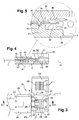
- this connector consists of a double housing 20 having a body 21 extending in a general plane P1 which corresponds to the plane of the light ribbons to be connected, that is to say according to the plane of the sheet of the figure 3 , and in the longitudinal direction XX of said ribbons.
- the housing comprises two covers 22, 23 one beside the other, pivotally articulated on the body by lateral hinges 29 extending along a hinge line L oriented in the longitudinal direction XX, the two lids being symmetrical with respect to a median plane P2 perpendicular to said longitudinal direction XX.
- the covers 22, 23 are clipped in the closed position on the body by engagement of a cutout 24 of the cover on a lug 25 of the body.
- the covers 22, 23 close housing 26 made in each part of the body and intended to receive the ends of the ribbons to be connected, the housing width corresponding to that of the ribbons.
- slides 27 are formed on the side walls of the housing 26 to guide the end of the ribbon during its insertion into the connector, as will be seen later.
- each wafer 3 corresponds to a track 10 'of the ribbon.
- the connectors for ribbons with a number of tracks other than two or four.
- the connectors carry on their cover and on the body, in the housing 26, polarization markings + and - to facilitate connections avoiding polarity errors.
- polarization markings + and - to facilitate connections avoiding polarity errors.
- the connector system according to the invention makes it possible to simply manage these inversions because the ends of the ribbons can be placed in the connectors without worrying about the orientation of the ribbon: the figure 2 shows that on one side of the corner, connected on the ribbon 1, the insulating layer 13 of the single ribbon 15 'is located on the top, and on the other side it is the support 12 of the ribbon 15' which is apparent, the conductive tracks being then on this side , below the support 12.
- the connection of the connector remains possible, because the electrical contact between the pads 14 and the pads 3 will then be via the tab 31 of the pads located towards the body of the housing 20 instead of being via the tab located towards the lid, as previously described.
- the connector 2a is then connected to the ribbon 15 'in the opposite direction of the connector 2.
- the said + and - marks make it possible to ensure, in relation to the corresponding tracks of the ribbon, that the polarities are well respected when the connector 2 is connected. both on the ribbon side of the single flat ribbon 15 'and on the ribbon side 1'.
- the tracks and their positions in the connectors may be identified by RGB-like markers - for example, as illustrated figure 8 , or equivalent locations.
- the invention is not limited to the embodiment of the connector described above solely by way of example.
- the pivoting cover could be replaced by any other cover system snap on the body and to ensure the locking tape by baffle systems or equivalent locking systems.
Landscapes
- Engineering & Computer Science (AREA)
- Physics & Mathematics (AREA)
- Microelectronics & Electronic Packaging (AREA)
- Optics & Photonics (AREA)
- General Engineering & Computer Science (AREA)
- Coupling Device And Connection With Printed Circuit (AREA)
- Led Device Packages (AREA)
- Multi-Conductor Connections (AREA)
- Connector Housings Or Holding Contact Members (AREA)
- Details Of Connecting Devices For Male And Female Coupling (AREA)
Claims (9)
- Steckverbinder für flache und flexible leuchtfähige Streifen (1, 1' ; 15, 15'), mit einer Vielzahl von parallelen Leiterbahnen (10) und LEDs, um ein Ende (19) eines solchen Streifens an einen anderen Streifen oder an ein anderes elektrisches Bauteil anzuschließen, wobei der Steckverbinder ein flaches, in einer allgemeinen Ebene (P1) verlaufendes Gehäuse aufweist, welches das Ende des besagten Streifens in besagter Ebene und eine Vielzahl von elektrischen Anschlusselementen aufnehmen kann, von denen jedes so positioniert ist, dass eine elektrische Verbindung mit einer Leiterbahn des Streifens gewährleistet ist; die elektrischen Anschlusselemente weisen an jedem Ende zwei Anschlusslaschen (31) auf, die untereinander einen in besagter Ebene (P1) verlaufenden Schlitz (32) bilden, der dadurch gekennzeichnet ist, dass darin ein Ende (14) einer Leiterbahn (10) in Längsrichtung (XX) und parallel zu besagter in Längsrichtung verlaufender Ebene des Streifens eingeführt werden kann, so dass beim Einstecken des Streifenendes durch das Festklemmen automatisch ein elektrischer Kontakt zwischen einer der Laschen des Verbindungselements und besagter Leiterbahn gewährleistet ist; der Steckverbinder (2) verfügt über Arretierungsvorrichtungen (41, 42), um den Streifen hinter seinen Endzonen (19), wo die elektrische Verbindung hergestellt wird, festzuklemmen; die Arretierungsvorrichtungen liegen so, dass sie nach dem Einführen der Enden der Leiterbahnen in besagte Schlitze (32) wirken, und weisen zu diesem Zweck quer zur Längsrichtung verlaufende Rippen (41) und Rillen (42) auf, die jeweils auf dem Korpus (21) des Gehäuses und auf einem Deckel (22, 23) des Steckverbinders, an einer zum Einstecken des Streifenendes (19) geeigneten Aufnahme (26) ausgebildet sind, wobei die Rippen und Rillen Windungen bilden, die auf den Streifen übertragen werden und ihn so mehrfach wechselseitig verbiegen, wodurch er arretiert wird.
- Steckverbinder nach Anspruch 1, dadurch gekennzeichnet, dass es sich bei den elektrischen Anschlusselementen um Plättchen (3) aus leitfähigem Metall handelt, die in einer senkrecht zur besagten allgemeinen Ebene (P1) verlaufenden Längsebene liegen und die an jedem Ende die besagten Laschen (31) aufweisen, die untereinander den besagten Schlitz (32) bilden.
- Steckverbinder nach Anspruch 2, dadurch gekennzeichnet, dass die Plättchen (3) in einem Korpus (21) des Gehäuses (20) festgehalten werden und dass die Laschen (31) auf jeder Seite in eine zum Einführen des Streifenendes (19) geeignete Aufnahme (26) ragen.
- Steckverbinder nach Anspruch 3, dadurch gekennzeichnet, dass in jeder Aufnahme (26) Gleitrillen (27) zur Führung der Ränder des Streifens vorhanden sind.
- Steckverbinder nach Anspruch 1, dadurch gekennzeichnet, dass der Deckel (22, 23) am Korpus (21) mittels eines seitlichen Scharniers (29) befestigt ist, und dass der Deckel (22, 23) mit Verriegelungsvorrichtungen (24, 25) auf dem Korpus (21) des Gehäuses verriegelt werden kann.
- Steckverbinder nach Anspruch 1, dadurch gekennzeichnet, dass der Deckel (22, 23) eine zusätzliche Rippe (40) aufweist, die auf die Laschen (31) der Plättchen drückt, wenn der Deckel geschlossen ist.
- Steckverbinder nach einem der Ansprüche 1 bis 5, dadurch gekennzeichnet, dass sein Korpus (20) und/oder die Deckel (22, 23) Polaritätskennzeichnungen (+, -) aufweisen.
- System bestehend aus leuchtfähigen, flachen, mit LEDs (11) versehenen Streifen, das aus einer Vielzahl von Streifenelementen (1, 1') besteht, die untereinander durch Steckverbinder verbunden sind, die nach einem der zuvor bezeichneten Ansprüche definiert sind.
- System bestehend aus leuchtfähigen, flachen Streifen nach Anspruch 8, dadurch gekennzeichnet, dass es spezifische Anschlusselemente zur Bildung von Ecken aufweist, bestehend aus einem einfachen, nur Leiterbahnen aufweisenden Streifen (15'), der in beliebigem Winkel gefaltet wird, und an jedem Ende einen Steckverbinder aufweist, der nach einem der zuvor bezeichneten Ansprüche definiert ist.
Applications Claiming Priority (2)
| Application Number | Priority Date | Filing Date | Title |
|---|---|---|---|
| FR0954554A FR2947669B1 (fr) | 2009-07-02 | 2009-07-02 | Connecteur de rubans conducteurs plats, notamment de rubans lumineux flexibles portant des diodes electroluminescentes |
| PCT/IB2010/053047 WO2011001411A1 (fr) | 2009-07-02 | 2010-07-02 | Connecteur de rubans conducteurs plats, notamment de rubans lumineux flexibles portant des diodes electroluminescentes |
Publications (2)
| Publication Number | Publication Date |
|---|---|
| EP2449636A1 EP2449636A1 (de) | 2012-05-09 |
| EP2449636B1 true EP2449636B1 (de) | 2016-03-09 |
Family
ID=41531559
Family Applications (1)
| Application Number | Title | Priority Date | Filing Date |
|---|---|---|---|
| EP10742267.7A Not-in-force EP2449636B1 (de) | 2009-07-02 | 2010-07-02 | Steckverbinder für flache leitfähige streifen, insbesondere flexible leuchtstreifen mit leds |
Country Status (4)
| Country | Link |
|---|---|
| EP (1) | EP2449636B1 (de) |
| CN (1) | CN102474031B (de) |
| FR (1) | FR2947669B1 (de) |
| WO (1) | WO2011001411A1 (de) |
Cited By (2)
| Publication number | Priority date | Publication date | Assignee | Title |
|---|---|---|---|---|
| EP4428432A4 (de) * | 2021-11-11 | 2025-03-12 | Suzhou Opple Lighting Co., Ltd. | Lampenstreifenverbinder und lampenstreifen |
| US20250230925A1 (en) * | 2024-01-11 | 2025-07-17 | Moda LLC | Led light strip assembly and connector for same |
Families Citing this family (15)
| Publication number | Priority date | Publication date | Assignee | Title |
|---|---|---|---|---|
| CN202189899U (zh) * | 2011-07-15 | 2012-04-11 | 张勇 | 用于led柔性滴胶灯条的电连接器 |
| CN102709727A (zh) * | 2012-05-30 | 2012-10-03 | 深圳市日上光电有限公司 | Led柔性电路板连接器 |
| CN102694298B (zh) * | 2012-05-31 | 2014-07-09 | 深圳市凯信光电有限公司 | Led灯带及其连接器和组件 |
| US9620889B1 (en) * | 2016-03-31 | 2017-04-11 | Elemental LED, Inc. | Power connectors for linear lighting |
| US9647349B1 (en) * | 2016-06-02 | 2017-05-09 | Elemental LED, Inc. | Through-insulation strip light connector |
| DE102017100165A1 (de) * | 2017-01-05 | 2018-07-05 | Jabil Optics Germany GmbH | Lichtemittierende Anordnung und lichtemittierendes System |
| CN107425298B (zh) * | 2017-07-22 | 2019-03-08 | 福建南新电缆有限公司 | 一种维修用电缆 |
| CN109217053B (zh) * | 2018-09-19 | 2023-10-24 | 深圳市拓普联科技术股份有限公司 | 免焊式灯带串接连接器及灯带免焊式串接方法 |
| FR3092475B1 (fr) * | 2019-02-11 | 2021-01-29 | Carlos Saiz | Connecteur électrique bipolaire à double serrage mécanique sur ruban conducteur |
| US11641070B2 (en) * | 2021-09-07 | 2023-05-02 | Alps Alpine Co., Ltd. | Amplifier fast connector |
| CN115264461B (zh) * | 2022-09-29 | 2023-01-03 | 深圳市爱特姆科技有限公司 | 一种灵活性强的快速连接器及led灯带 |
| TWI847418B (zh) * | 2022-12-08 | 2024-07-01 | 禾昌興業股份有限公司 | 模組連接器 |
| CN115789585A (zh) * | 2022-12-28 | 2023-03-14 | 中山市星美达照明电器有限公司 | 一种高效多角度转换的灯带及其转换方法 |
| GB2628796B (en) * | 2023-04-04 | 2025-06-04 | Luceco Uk Ltd | Electrical connection system |
| USD1103927S1 (en) | 2024-01-11 | 2025-12-02 | Ip Llc | Light strip connector |
Family Cites Families (14)
| Publication number | Priority date | Publication date | Assignee | Title |
|---|---|---|---|---|
| GB1491694A (en) * | 1974-01-07 | 1977-11-09 | Bunker Ramo | Flat-cable connector having insulation piercing contacts |
| US4027941A (en) * | 1976-11-01 | 1977-06-07 | Thomas & Betts Corporation | Termination method and apparatus for flat flexible cable |
| US4415215A (en) * | 1981-06-24 | 1983-11-15 | Calman Goozner | Solderless electrical splice |
| US4820193A (en) * | 1988-04-04 | 1989-04-11 | Thomas & Betts Corporation | Panel mounted electrical connector including means for providing an indication of correct conductor termination |
| US5337225A (en) | 1993-01-06 | 1994-08-09 | The Standard Products Company | Lighting strip system |
| JPH06325837A (ja) * | 1993-05-10 | 1994-11-25 | Kel Corp | フレキシブルケーブルコネクタ |
| JP2001210410A (ja) * | 2000-01-28 | 2001-08-03 | Yazaki Corp | フラット回路体の端末構造 |
| DE10065972A1 (de) * | 2000-05-29 | 2002-07-11 | Taller Gmbh | Flexfoliensteckerzugentlastung |
| FR2814864B1 (fr) * | 2000-10-02 | 2005-01-14 | Fci Automotive France | Dispositif de maintien des zones de sertissage d'un circuit souple dans un connecteur electrique et le connecteur equipe |
| DE10250927B3 (de) * | 2002-10-31 | 2004-08-12 | Fci | Steckverbinder zum Verbinden zweier Leiter |
| US6914194B2 (en) | 2003-10-29 | 2005-07-05 | Ben Fan | Flexible LED cable light |
| JP2006004723A (ja) * | 2004-06-16 | 2006-01-05 | Omron Corp | コネクタ、当該コネクタを備えた光源モジュール及び面光源装置 |
| JP4938303B2 (ja) * | 2005-12-16 | 2012-05-23 | 日本圧着端子製造株式会社 | コネクタ |
| US7547214B2 (en) * | 2007-05-22 | 2009-06-16 | Tyco Electronics Corporation | Edge-to-edge connector system for electronic devices |
-
2009
- 2009-07-02 FR FR0954554A patent/FR2947669B1/fr not_active Expired - Fee Related
-
2010
- 2010-07-02 EP EP10742267.7A patent/EP2449636B1/de not_active Not-in-force
- 2010-07-02 CN CN201080027557.4A patent/CN102474031B/zh not_active Expired - Fee Related
- 2010-07-02 WO PCT/IB2010/053047 patent/WO2011001411A1/fr not_active Ceased
Cited By (3)
| Publication number | Priority date | Publication date | Assignee | Title |
|---|---|---|---|---|
| EP4428432A4 (de) * | 2021-11-11 | 2025-03-12 | Suzhou Opple Lighting Co., Ltd. | Lampenstreifenverbinder und lampenstreifen |
| US20250230925A1 (en) * | 2024-01-11 | 2025-07-17 | Moda LLC | Led light strip assembly and connector for same |
| US12535203B2 (en) * | 2024-01-11 | 2026-01-27 | Ip Llc A Series Of Moda Light Llc | LED light strip assembly and connector for same |
Also Published As
| Publication number | Publication date |
|---|---|
| HK1165622A1 (zh) | 2012-10-05 |
| CN102474031A (zh) | 2012-05-23 |
| FR2947669B1 (fr) | 2014-04-25 |
| EP2449636A1 (de) | 2012-05-09 |
| FR2947669A1 (fr) | 2011-01-07 |
| WO2011001411A1 (fr) | 2011-01-06 |
| CN102474031B (zh) | 2015-07-01 |
Similar Documents
| Publication | Publication Date | Title |
|---|---|---|
| EP2449636B1 (de) | Steckverbinder für flache leitfähige streifen, insbesondere flexible leuchtstreifen mit leds | |
| FR2654557A1 (fr) | Organe de contact electrique male et boiter de connexions electriques correspondant. | |
| LU83885A1 (fr) | Connecteur electrique pour conducteur isole | |
| EP2639913B1 (de) | Vorrichtung zum Befestigen einer elektrischen Triebwerksausrüstung in einem Luftfahrzeug | |
| FR2699010A1 (fr) | Organe de contact électrique femelle. | |
| EP3227966B1 (de) | Elektrisches verbindungselement, das einen stromdrahtisolierungsmantel penetriert | |
| FR2899023A1 (fr) | Perfectionnements introduits dans les systemes de connexion par interverrouillage applicables aux dispositifs electriques | |
| EP0375654B1 (de) | Zusammenbau einer Stecklampenfassung und einer Lichtleiste | |
| FR2570550A1 (fr) | Perfectionnements aux dispositifs de connexion pour cartes de circuits imprimes | |
| EP1865579B1 (de) | Selbstabisolierende Verbindungsanschluss und elektrisches Gerät mit einem solchen Anschluss | |
| FR2587147A1 (fr) | Outil de pose formant magasion pour reperes, en particulier pour reperes de cablage | |
| EP0166627A1 (de) | Verbindung einer Schaltung auf einem starren Träger mit einer Schaltung auf mindestens einem biegsamen Träger | |
| FR2736199A1 (fr) | Carcasse pour transformateur, et transformateur comportant une telle carcasse | |
| FR2551272A1 (fr) | Prise electrique isolee et etanche | |
| EP1519445B1 (de) | Elektrisches Gerät mit einem isolierten Gehäuse und einer in dem Gehäuse angeordneten automatischen Anschlussklemme | |
| EP3349305B1 (de) | Verbessertes elektrisches anschlusskit | |
| FR2960685A1 (fr) | Perfectionnements aux dispositifs de liaison pour affiches publicitaires d'un panneau deroulant | |
| FR2509914A1 (fr) | Connecteur multiple pour circuit imprime | |
| FR2537349A1 (fr) | Dispositif de connexion a contacts et procede de montage desdits contacts dans le dispositif | |
| FR2920920A1 (fr) | Dispositif de raccordement electrique | |
| EP0597744B1 (de) | Elektrische Verbindungsvorrichtung | |
| EP1564860B1 (de) | Wanddickeanpassungsflanschgehäuse für eine dünne Wand | |
| EP1496575B1 (de) | Steckkontakt | |
| EP0805519A1 (de) | Stecker mit integrierten Anschlüssen und Rückwandverbindung mit Schneidkontakten | |
| FR2519802A1 (fr) | Porte-fusible notamment porte-fusible d'appareil |
Legal Events
| Date | Code | Title | Description |
|---|---|---|---|
| PUAI | Public reference made under article 153(3) epc to a published international application that has entered the european phase |
Free format text: ORIGINAL CODE: 0009012 |
|
| 17P | Request for examination filed |
Effective date: 20120105 |
|
| AK | Designated contracting states |
Kind code of ref document: A1 Designated state(s): AL AT BE BG CH CY CZ DE DK EE ES FI FR GB GR HR HU IE IS IT LI LT LU LV MC MK MT NL NO PL PT RO SE SI SK SM TR |
|
| REG | Reference to a national code |
Ref country code: HK Ref legal event code: DE Ref document number: 1165622 Country of ref document: HK |
|
| DAX | Request for extension of the european patent (deleted) | ||
| GRAP | Despatch of communication of intention to grant a patent |
Free format text: ORIGINAL CODE: EPIDOSNIGR1 |
|
| INTG | Intention to grant announced |
Effective date: 20151113 |
|
| RAP1 | Party data changed (applicant data changed or rights of an application transferred) |
Owner name: YANTEC |
|
| GRAS | Grant fee paid |
Free format text: ORIGINAL CODE: EPIDOSNIGR3 |
|
| GRAA | (expected) grant |
Free format text: ORIGINAL CODE: 0009210 |
|
| AK | Designated contracting states |
Kind code of ref document: B1 Designated state(s): AL AT BE BG CH CY CZ DE DK EE ES FI FR GB GR HR HU IE IS IT LI LT LU LV MC MK MT NL NO PL PT RO SE SI SK SM TR |
|
| REG | Reference to a national code |
Ref country code: GB Ref legal event code: FG4D Free format text: NOT ENGLISH |
|
| REG | Reference to a national code |
Ref country code: AT Ref legal event code: REF Ref document number: 780117 Country of ref document: AT Kind code of ref document: T Effective date: 20160315 Ref country code: CH Ref legal event code: EP |
|
| REG | Reference to a national code |
Ref country code: IE Ref legal event code: FG4D Free format text: LANGUAGE OF EP DOCUMENT: FRENCH |
|
| REG | Reference to a national code |
Ref country code: DE Ref legal event code: R096 Ref document number: 602010031056 Country of ref document: DE |
|
| REG | Reference to a national code |
Ref country code: FR Ref legal event code: PLFP Year of fee payment: 7 |
|
| REG | Reference to a national code |
Ref country code: LT Ref legal event code: MG4D |
|
| REG | Reference to a national code |
Ref country code: NL Ref legal event code: MP Effective date: 20160309 |
|
| PG25 | Lapsed in a contracting state [announced via postgrant information from national office to epo] |
Ref country code: NO Free format text: LAPSE BECAUSE OF FAILURE TO SUBMIT A TRANSLATION OF THE DESCRIPTION OR TO PAY THE FEE WITHIN THE PRESCRIBED TIME-LIMIT Effective date: 20160609 Ref country code: FI Free format text: LAPSE BECAUSE OF FAILURE TO SUBMIT A TRANSLATION OF THE DESCRIPTION OR TO PAY THE FEE WITHIN THE PRESCRIBED TIME-LIMIT Effective date: 20160309 Ref country code: ES Free format text: LAPSE BECAUSE OF FAILURE TO SUBMIT A TRANSLATION OF THE DESCRIPTION OR TO PAY THE FEE WITHIN THE PRESCRIBED TIME-LIMIT Effective date: 20160309 Ref country code: HR Free format text: LAPSE BECAUSE OF FAILURE TO SUBMIT A TRANSLATION OF THE DESCRIPTION OR TO PAY THE FEE WITHIN THE PRESCRIBED TIME-LIMIT Effective date: 20160309 Ref country code: GR Free format text: LAPSE BECAUSE OF FAILURE TO SUBMIT A TRANSLATION OF THE DESCRIPTION OR TO PAY THE FEE WITHIN THE PRESCRIBED TIME-LIMIT Effective date: 20160610 |
|
| REG | Reference to a national code |
Ref country code: AT Ref legal event code: MK05 Ref document number: 780117 Country of ref document: AT Kind code of ref document: T Effective date: 20160309 |
|
| PG25 | Lapsed in a contracting state [announced via postgrant information from national office to epo] |
Ref country code: LV Free format text: LAPSE BECAUSE OF FAILURE TO SUBMIT A TRANSLATION OF THE DESCRIPTION OR TO PAY THE FEE WITHIN THE PRESCRIBED TIME-LIMIT Effective date: 20160309 Ref country code: LT Free format text: LAPSE BECAUSE OF FAILURE TO SUBMIT A TRANSLATION OF THE DESCRIPTION OR TO PAY THE FEE WITHIN THE PRESCRIBED TIME-LIMIT Effective date: 20160309 Ref country code: PL Free format text: LAPSE BECAUSE OF FAILURE TO SUBMIT A TRANSLATION OF THE DESCRIPTION OR TO PAY THE FEE WITHIN THE PRESCRIBED TIME-LIMIT Effective date: 20160309 Ref country code: SE Free format text: LAPSE BECAUSE OF FAILURE TO SUBMIT A TRANSLATION OF THE DESCRIPTION OR TO PAY THE FEE WITHIN THE PRESCRIBED TIME-LIMIT Effective date: 20160309 Ref country code: NL Free format text: LAPSE BECAUSE OF FAILURE TO SUBMIT A TRANSLATION OF THE DESCRIPTION OR TO PAY THE FEE WITHIN THE PRESCRIBED TIME-LIMIT Effective date: 20160309 |
|
| PG25 | Lapsed in a contracting state [announced via postgrant information from national office to epo] |
Ref country code: EE Free format text: LAPSE BECAUSE OF FAILURE TO SUBMIT A TRANSLATION OF THE DESCRIPTION OR TO PAY THE FEE WITHIN THE PRESCRIBED TIME-LIMIT Effective date: 20160309 Ref country code: IS Free format text: LAPSE BECAUSE OF FAILURE TO SUBMIT A TRANSLATION OF THE DESCRIPTION OR TO PAY THE FEE WITHIN THE PRESCRIBED TIME-LIMIT Effective date: 20160709 |
|
| PG25 | Lapsed in a contracting state [announced via postgrant information from national office to epo] |
Ref country code: PT Free format text: LAPSE BECAUSE OF FAILURE TO SUBMIT A TRANSLATION OF THE DESCRIPTION OR TO PAY THE FEE WITHIN THE PRESCRIBED TIME-LIMIT Effective date: 20160711 Ref country code: CZ Free format text: LAPSE BECAUSE OF FAILURE TO SUBMIT A TRANSLATION OF THE DESCRIPTION OR TO PAY THE FEE WITHIN THE PRESCRIBED TIME-LIMIT Effective date: 20160309 Ref country code: AT Free format text: LAPSE BECAUSE OF FAILURE TO SUBMIT A TRANSLATION OF THE DESCRIPTION OR TO PAY THE FEE WITHIN THE PRESCRIBED TIME-LIMIT Effective date: 20160309 Ref country code: SK Free format text: LAPSE BECAUSE OF FAILURE TO SUBMIT A TRANSLATION OF THE DESCRIPTION OR TO PAY THE FEE WITHIN THE PRESCRIBED TIME-LIMIT Effective date: 20160309 Ref country code: SM Free format text: LAPSE BECAUSE OF FAILURE TO SUBMIT A TRANSLATION OF THE DESCRIPTION OR TO PAY THE FEE WITHIN THE PRESCRIBED TIME-LIMIT Effective date: 20160309 Ref country code: RO Free format text: LAPSE BECAUSE OF FAILURE TO SUBMIT A TRANSLATION OF THE DESCRIPTION OR TO PAY THE FEE WITHIN THE PRESCRIBED TIME-LIMIT Effective date: 20160309 |
|
| REG | Reference to a national code |
Ref country code: DE Ref legal event code: R097 Ref document number: 602010031056 Country of ref document: DE |
|
| PG25 | Lapsed in a contracting state [announced via postgrant information from national office to epo] |
Ref country code: IT Free format text: LAPSE BECAUSE OF FAILURE TO SUBMIT A TRANSLATION OF THE DESCRIPTION OR TO PAY THE FEE WITHIN THE PRESCRIBED TIME-LIMIT Effective date: 20160309 Ref country code: BE Free format text: LAPSE BECAUSE OF NON-PAYMENT OF DUE FEES Effective date: 20160731 |
|
| PLBE | No opposition filed within time limit |
Free format text: ORIGINAL CODE: 0009261 |
|
| STAA | Information on the status of an ep patent application or granted ep patent |
Free format text: STATUS: NO OPPOSITION FILED WITHIN TIME LIMIT |
|
| PG25 | Lapsed in a contracting state [announced via postgrant information from national office to epo] |
Ref country code: DK Free format text: LAPSE BECAUSE OF FAILURE TO SUBMIT A TRANSLATION OF THE DESCRIPTION OR TO PAY THE FEE WITHIN THE PRESCRIBED TIME-LIMIT Effective date: 20160309 |
|
| REG | Reference to a national code |
Ref country code: DE Ref legal event code: R119 Ref document number: 602010031056 Country of ref document: DE |
|
| 26N | No opposition filed |
Effective date: 20161212 |
|
| PG25 | Lapsed in a contracting state [announced via postgrant information from national office to epo] |
Ref country code: BG Free format text: LAPSE BECAUSE OF FAILURE TO SUBMIT A TRANSLATION OF THE DESCRIPTION OR TO PAY THE FEE WITHIN THE PRESCRIBED TIME-LIMIT Effective date: 20160609 |
|
| REG | Reference to a national code |
Ref country code: CH Ref legal event code: PL |
|
| GBPC | Gb: european patent ceased through non-payment of renewal fee |
Effective date: 20160702 |
|
| PG25 | Lapsed in a contracting state [announced via postgrant information from national office to epo] |
Ref country code: MC Free format text: LAPSE BECAUSE OF FAILURE TO SUBMIT A TRANSLATION OF THE DESCRIPTION OR TO PAY THE FEE WITHIN THE PRESCRIBED TIME-LIMIT Effective date: 20160309 |
|
| REG | Reference to a national code |
Ref country code: HK Ref legal event code: GR Ref document number: 1165622 Country of ref document: HK |
|
| PG25 | Lapsed in a contracting state [announced via postgrant information from national office to epo] |
Ref country code: DE Free format text: LAPSE BECAUSE OF NON-PAYMENT OF DUE FEES Effective date: 20170201 Ref country code: LI Free format text: LAPSE BECAUSE OF NON-PAYMENT OF DUE FEES Effective date: 20160731 Ref country code: CH Free format text: LAPSE BECAUSE OF NON-PAYMENT OF DUE FEES Effective date: 20160731 |
|
| REG | Reference to a national code |
Ref country code: IE Ref legal event code: MM4A |
|
| PG25 | Lapsed in a contracting state [announced via postgrant information from national office to epo] |
Ref country code: GB Free format text: LAPSE BECAUSE OF NON-PAYMENT OF DUE FEES Effective date: 20160702 Ref country code: SI Free format text: LAPSE BECAUSE OF FAILURE TO SUBMIT A TRANSLATION OF THE DESCRIPTION OR TO PAY THE FEE WITHIN THE PRESCRIBED TIME-LIMIT Effective date: 20160309 |
|
| REG | Reference to a national code |
Ref country code: FR Ref legal event code: PLFP Year of fee payment: 8 |
|
| PG25 | Lapsed in a contracting state [announced via postgrant information from national office to epo] |
Ref country code: IE Free format text: LAPSE BECAUSE OF NON-PAYMENT OF DUE FEES Effective date: 20160702 |
|
| PG25 | Lapsed in a contracting state [announced via postgrant information from national office to epo] |
Ref country code: LU Free format text: LAPSE BECAUSE OF NON-PAYMENT OF DUE FEES Effective date: 20160702 |
|
| PG25 | Lapsed in a contracting state [announced via postgrant information from national office to epo] |
Ref country code: CY Free format text: LAPSE BECAUSE OF FAILURE TO SUBMIT A TRANSLATION OF THE DESCRIPTION OR TO PAY THE FEE WITHIN THE PRESCRIBED TIME-LIMIT Effective date: 20160309 Ref country code: HU Free format text: LAPSE BECAUSE OF FAILURE TO SUBMIT A TRANSLATION OF THE DESCRIPTION OR TO PAY THE FEE WITHIN THE PRESCRIBED TIME-LIMIT; INVALID AB INITIO Effective date: 20100702 |
|
| REG | Reference to a national code |
Ref country code: FR Ref legal event code: PLFP Year of fee payment: 9 |
|
| PG25 | Lapsed in a contracting state [announced via postgrant information from national office to epo] |
Ref country code: MT Free format text: LAPSE BECAUSE OF FAILURE TO SUBMIT A TRANSLATION OF THE DESCRIPTION OR TO PAY THE FEE WITHIN THE PRESCRIBED TIME-LIMIT Effective date: 20160309 Ref country code: TR Free format text: LAPSE BECAUSE OF FAILURE TO SUBMIT A TRANSLATION OF THE DESCRIPTION OR TO PAY THE FEE WITHIN THE PRESCRIBED TIME-LIMIT Effective date: 20160309 Ref country code: MK Free format text: LAPSE BECAUSE OF FAILURE TO SUBMIT A TRANSLATION OF THE DESCRIPTION OR TO PAY THE FEE WITHIN THE PRESCRIBED TIME-LIMIT Effective date: 20160309 |
|
| PG25 | Lapsed in a contracting state [announced via postgrant information from national office to epo] |
Ref country code: AL Free format text: LAPSE BECAUSE OF FAILURE TO SUBMIT A TRANSLATION OF THE DESCRIPTION OR TO PAY THE FEE WITHIN THE PRESCRIBED TIME-LIMIT Effective date: 20160309 |
|
| PGFP | Annual fee paid to national office [announced via postgrant information from national office to epo] |
Ref country code: FR Payment date: 20190429 Year of fee payment: 10 |
|
| PG25 | Lapsed in a contracting state [announced via postgrant information from national office to epo] |
Ref country code: FR Free format text: LAPSE BECAUSE OF NON-PAYMENT OF DUE FEES Effective date: 20200731 |