EP2449685B1 - Système récepteur multicanal et procédé de surveillance de récepteur multicanal - Google Patents
Système récepteur multicanal et procédé de surveillance de récepteur multicanal Download PDFInfo
- Publication number
- EP2449685B1 EP2449685B1 EP09846744.2A EP09846744A EP2449685B1 EP 2449685 B1 EP2449685 B1 EP 2449685B1 EP 09846744 A EP09846744 A EP 09846744A EP 2449685 B1 EP2449685 B1 EP 2449685B1
- Authority
- EP
- European Patent Office
- Prior art keywords
- mixer
- reference signal
- input
- receiver system
- multichannel receiver
- Prior art date
- Legal status (The legal status is an assumption and is not a legal conclusion. Google has not performed a legal analysis and makes no representation as to the accuracy of the status listed.)
- Active
Links
Images

Classifications
-
- G—PHYSICS
- G01—MEASURING; TESTING
- G01S—RADIO DIRECTION-FINDING; RADIO NAVIGATION; DETERMINING DISTANCE OR VELOCITY BY USE OF RADIO WAVES; LOCATING OR PRESENCE-DETECTING BY USE OF THE REFLECTION OR RERADIATION OF RADIO WAVES; ANALOGOUS ARRANGEMENTS USING OTHER WAVES
- G01S7/00—Details of systems according to groups G01S13/00, G01S15/00, G01S17/00
- G01S7/02—Details of systems according to groups G01S13/00, G01S15/00, G01S17/00 of systems according to group G01S13/00
- G01S7/40—Means for monitoring or calibrating
- G01S7/4004—Means for monitoring or calibrating of parts of a radar system
- G01S7/4021—Means for monitoring or calibrating of parts of a radar system of receivers
-
- G—PHYSICS
- G01—MEASURING; TESTING
- G01S—RADIO DIRECTION-FINDING; RADIO NAVIGATION; DETERMINING DISTANCE OR VELOCITY BY USE OF RADIO WAVES; LOCATING OR PRESENCE-DETECTING BY USE OF THE REFLECTION OR RERADIATION OF RADIO WAVES; ANALOGOUS ARRANGEMENTS USING OTHER WAVES
- G01S13/00—Systems using the reflection or reradiation of radio waves, e.g. radar systems; Analogous systems using reflection or reradiation of waves whose nature or wavelength is irrelevant or unspecified
- G01S13/88—Radar or analogous systems specially adapted for specific applications
- G01S13/93—Radar or analogous systems specially adapted for specific applications for anti-collision purposes
- G01S13/931—Radar or analogous systems specially adapted for specific applications for anti-collision purposes of land vehicles
-
- G—PHYSICS
- G01—MEASURING; TESTING
- G01S—RADIO DIRECTION-FINDING; RADIO NAVIGATION; DETERMINING DISTANCE OR VELOCITY BY USE OF RADIO WAVES; LOCATING OR PRESENCE-DETECTING BY USE OF THE REFLECTION OR RERADIATION OF RADIO WAVES; ANALOGOUS ARRANGEMENTS USING OTHER WAVES
- G01S13/00—Systems using the reflection or reradiation of radio waves, e.g. radar systems; Analogous systems using reflection or reradiation of waves whose nature or wavelength is irrelevant or unspecified
- G01S13/88—Radar or analogous systems specially adapted for specific applications
- G01S13/93—Radar or analogous systems specially adapted for specific applications for anti-collision purposes
- G01S13/931—Radar or analogous systems specially adapted for specific applications for anti-collision purposes of land vehicles
- G01S2013/93185—Controlling the brakes
-
- G—PHYSICS
- G01—MEASURING; TESTING
- G01S—RADIO DIRECTION-FINDING; RADIO NAVIGATION; DETERMINING DISTANCE OR VELOCITY BY USE OF RADIO WAVES; LOCATING OR PRESENCE-DETECTING BY USE OF THE REFLECTION OR RERADIATION OF RADIO WAVES; ANALOGOUS ARRANGEMENTS USING OTHER WAVES
- G01S13/00—Systems using the reflection or reradiation of radio waves, e.g. radar systems; Analogous systems using reflection or reradiation of waves whose nature or wavelength is irrelevant or unspecified
- G01S13/88—Radar or analogous systems specially adapted for specific applications
- G01S13/93—Radar or analogous systems specially adapted for specific applications for anti-collision purposes
- G01S13/931—Radar or analogous systems specially adapted for specific applications for anti-collision purposes of land vehicles
- G01S2013/9321—Velocity regulation, e.g. cruise control
-
- G—PHYSICS
- G01—MEASURING; TESTING
- G01S—RADIO DIRECTION-FINDING; RADIO NAVIGATION; DETERMINING DISTANCE OR VELOCITY BY USE OF RADIO WAVES; LOCATING OR PRESENCE-DETECTING BY USE OF THE REFLECTION OR RERADIATION OF RADIO WAVES; ANALOGOUS ARRANGEMENTS USING OTHER WAVES
- G01S3/00—Direction-finders for determining the direction from which infrasonic, sonic, ultrasonic or electromagnetic waves, or particle emission, not having a directional significance, are being received
- G01S3/02—Direction-finders for determining the direction from which infrasonic, sonic, ultrasonic or electromagnetic waves, or particle emission, not having a directional significance, are being received using radio waves
- G01S3/14—Systems for determining direction or deviation from predetermined direction
- G01S3/46—Systems for determining direction or deviation from predetermined direction using antennas spaced apart and measuring phase or time difference between signals therefrom, i.e. path-difference systems
- G01S3/48—Systems for determining direction or deviation from predetermined direction using antennas spaced apart and measuring phase or time difference between signals therefrom, i.e. path-difference systems the waves arriving at the antennas being continuous or intermittent and the phase difference of signals derived therefrom being measured
-
- G—PHYSICS
- G01—MEASURING; TESTING
- G01S—RADIO DIRECTION-FINDING; RADIO NAVIGATION; DETERMINING DISTANCE OR VELOCITY BY USE OF RADIO WAVES; LOCATING OR PRESENCE-DETECTING BY USE OF THE REFLECTION OR RERADIATION OF RADIO WAVES; ANALOGOUS ARRANGEMENTS USING OTHER WAVES
- G01S7/00—Details of systems according to groups G01S13/00, G01S15/00, G01S17/00
- G01S7/02—Details of systems according to groups G01S13/00, G01S15/00, G01S17/00 of systems according to group G01S13/00
- G01S7/40—Means for monitoring or calibrating
- G01S7/4052—Means for monitoring or calibrating by simulation of echoes
-
- G—PHYSICS
- G01—MEASURING; TESTING
- G01S—RADIO DIRECTION-FINDING; RADIO NAVIGATION; DETERMINING DISTANCE OR VELOCITY BY USE OF RADIO WAVES; LOCATING OR PRESENCE-DETECTING BY USE OF THE REFLECTION OR RERADIATION OF RADIO WAVES; ANALOGOUS ARRANGEMENTS USING OTHER WAVES
- G01S7/00—Details of systems according to groups G01S13/00, G01S15/00, G01S17/00
- G01S7/02—Details of systems according to groups G01S13/00, G01S15/00, G01S17/00 of systems according to group G01S13/00
- G01S7/40—Means for monitoring or calibrating
- G01S7/4052—Means for monitoring or calibrating by simulation of echoes
- G01S7/406—Means for monitoring or calibrating by simulation of echoes using internally generated reference signals, e.g. via delay line, via RF or IF signal injection or via integrated reference reflector or transponder
-
- G—PHYSICS
- G01—MEASURING; TESTING
- G01S—RADIO DIRECTION-FINDING; RADIO NAVIGATION; DETERMINING DISTANCE OR VELOCITY BY USE OF RADIO WAVES; LOCATING OR PRESENCE-DETECTING BY USE OF THE REFLECTION OR RERADIATION OF RADIO WAVES; ANALOGOUS ARRANGEMENTS USING OTHER WAVES
- G01S7/00—Details of systems according to groups G01S13/00, G01S15/00, G01S17/00
- G01S7/02—Details of systems according to groups G01S13/00, G01S15/00, G01S17/00 of systems according to group G01S13/00
- G01S7/40—Means for monitoring or calibrating
- G01S7/4052—Means for monitoring or calibrating by simulation of echoes
- G01S7/406—Means for monitoring or calibrating by simulation of echoes using internally generated reference signals, e.g. via delay line, via RF or IF signal injection or via integrated reference reflector or transponder
- G01S7/4069—Means for monitoring or calibrating by simulation of echoes using internally generated reference signals, e.g. via delay line, via RF or IF signal injection or via integrated reference reflector or transponder involving a RF signal injection
-
- G—PHYSICS
- G01—MEASURING; TESTING
- G01S—RADIO DIRECTION-FINDING; RADIO NAVIGATION; DETERMINING DISTANCE OR VELOCITY BY USE OF RADIO WAVES; LOCATING OR PRESENCE-DETECTING BY USE OF THE REFLECTION OR RERADIATION OF RADIO WAVES; ANALOGOUS ARRANGEMENTS USING OTHER WAVES
- G01S7/00—Details of systems according to groups G01S13/00, G01S15/00, G01S17/00
- G01S7/02—Details of systems according to groups G01S13/00, G01S15/00, G01S17/00 of systems according to group G01S13/00
- G01S7/40—Means for monitoring or calibrating
- G01S7/4052—Means for monitoring or calibrating by simulation of echoes
- G01S7/4082—Means for monitoring or calibrating by simulation of echoes using externally generated reference signals, e.g. via remote reflector or transponder
- G01S7/4091—Means for monitoring or calibrating by simulation of echoes using externally generated reference signals, e.g. via remote reflector or transponder during normal radar operation
Definitions
- This invention in general relates to receivers and more specifically to a multichannel receiver system, a method for multichannel receiver monitoring, a radar system and a vehicle.
- Multichannel receiver systems are used in communication with antenna arrays to build phased arrays for example in radar systems, for enabling beam steering while avoiding mechanical moving parts of the radar system itself, which may be used for automotive applications.
- Each receiving path of a multichannel receiver system may introduce a different absolute phase shift to the particular signal received on its receive antenna, which may be compensated by a calibration value determined either during a calibration phase, which may be repeated during dedicated timeslots or during regular receive operation without dedicated calibration phase.
- US 3,471,855 A describes a system for generating test signals for an array of receiver channels.
- the system comprises a plurality of amplifiers and mixers, wherein each of the amplifiers has a dedicated input connected to an own input line. Each of these input lines is arranged to provide a corresponding one of a plurality of received antenna signals.
- Each of the local oscillators provides a local oscillator signal to a corresponding one of the mixers.
- Each of the mixers has an output to provide a own output signal.
- An upconversion mixer has a first mixer input, a second mixer input, and a mixer output.
- the first mixer input receives a reference signal indirectly generated by a phase-locked loop synthesizer and a waveform generator.
- the second mixer input is connected to the local oscillators via a summer (signal combining unit).
- the mixer output provides upconverted reference signals to a plurality of directional couplers each of which is connected to a corresponding one of said input lines of the amplifiers.
- US 4,394,659 A describes a monopulse radar comprising a pilot signal generator having two receiver circuits. Each receiver circuit has a first input, a second input, and an output. The first input is connected to a corresponding input line arranged to provide a corresponding received signal. The second input of each receiver circuit is connected to a same local oscillator to provide a local oscillator signal.
- a pilot signal generator provides an upconverted pilot signal via a signal splitter to a pair of directional couplers, each of them connected to a corresponding one of said input lines providing a corresponding received signal.
- the pilot signal generator is fed by an output signal of an upconversion mixer having a first mixer input and a second mixer input. The first mixer input receives a reference signal from a coherent oscillator. The second mixer input is connected to an output of the local oscillator.
- the present invention provides a multichannel receiver system, a method for multichannel receiver monitoring, a radar system, a vehicle, and a computer program product as described in the accompanying claims.
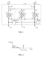
- the multichannel receiver system 10 comprises a first plurality of receiver circuits 12, 14. Each of these receiver circuits 12, 14 have a first input 16, 18 connected to a corresponding one of a second plurality of input lines 20, 22, each input line 20, 22 being arranged to provide a corresponding one of a third plurality of received signals. And the receiver circuits 12, 14 each comprise a second input 24, 26 connected to a local oscillator 28 arranged to provide a local oscillator signal, and an output 30, 32 arranged to provide a corresponding one of a fourth plurality of output signals 34, 36.
- the multichannel receiver system 10 also comprises an upconversion mixer 38 having a first mixer input 40 for receiving a reference signal 42, a second mixer input 44 connected to the local oscillator 28, and a mixer output 46 providing an upconverted reference signal to a fifth plurality of directional couplers 48, 50, each directional coupler 48, 50 being connected to a corresponding one of the second plurality of input lines 20, 22.
- an upconversion mixer 38 having a first mixer input 40 for receiving a reference signal 42, a second mixer input 44 connected to the local oscillator 28, and a mixer output 46 providing an upconverted reference signal to a fifth plurality of directional couplers 48, 50, each directional coupler 48, 50 being connected to a corresponding one of the second plurality of input lines 20, 22.
- the input lines 20, 22 may carry the received signals.
- a signal may be a change of a physical quantity carrying information, for example an electromagnetic wave.
- a signal may for example be a radio frequency signal or an optical signal.
- Each of the second plurality of input lines 20, 22 may be connected to a corresponding receive antenna 58, 60 of a receive antenna array.
- input lines 20, 22 may be connected to wire lines instead of antennas.
- the example system shown in FIG. 1 illustrating an embodiment of a multichannel receiver system may be a dual channel receiver system. It should be noted that the receiver system may comprise more than two receiving paths.
- Received signals may be radio frequency signals or millimetre wave signals, for example modulated with a carrier signal.
- a receiver circuit 12, 14 may be a signal converter, for example a downconverter circuit or downconversion mixer, for example for de-modulating the received signal and providing an output signal 34, 36.
- An output signal may be an intermediate frequency signal or a baseband low-frequency signal.
- receiver circuits may also receive an identical local oscillator signal from a local oscillator circuit 28.
- the shown multichannel receiver system 10 may be used with radar signals.
- beam steering may be applied to the antenna array.
- the detection of the main lobe of the received radiation pattern may be achieved by evaluating the relative phases of the received signals, for example the received radio frequency signals.
- the receiver system 10 connected to an antenna array 58, 60 may be used, wherein an angular position of a target is translated from the arrival time of the reflected signal at the antennas to relative phase differences in the output signals, which may be the downconverted baseband signals.
- AOA angle-of-arrival
- Relative phase differences between the received signals may be determined, although all receiving paths, i.e. receiver circuit 12, 14 and input line 20, 22 connected to an antenna 58, 60, may introduce phase shifts and changes of magnitude to the particular received signal. However, relative phase differences may be evaluated, if the introduced phase shifts of all receiving paths or channels are known. These phase shifts may vary, for example due to differences in the receiver hardware used arising for example from production variations, die assembly or aging over lifetime. Although the upconversion mixer may also introduce a phase shift, it may be identically fed into the receiving paths and therefore may not affect relative phase changes between received signals. This may also apply to possible amplitude changes caused by the coupled in reference signal.
- a deviation of phase shift for a particular channel may be determined, which may allow for calibration of the receiver system 10.
- the upconversion mixer 38 may be a modulator circuit receiving a reference signal or test signal 42, which may be a low-frequency and very narrow bandwidth signal, and the same local oscillator 28 signal as the receiver circuits 12, 14.
- the upconversion mixer 38 may mix both signals for generating an upconverted reference signal in a frequency band close to the received signal frequency band. However, a different local oscillator signal may be used, if the upconverted reference signal has a frequency close to the frequency band of the received signal.
- a frequency of the reference signal may be chosen such as not to interfere with the signals received e.g. via the antennas 58, 60 during regular operation.
- Directional coupler 48, 50 connected to at least some of the input lines 20, 22 of the receiver system 10 may receive the upconverted reference signal and couple it into the received signal on the particular input line 20, 22.
- the coupled in upconverted reference signal may then be downconverted, together with the signal received at the antenna 58, 60 and may provide a reference within the output signal 34, 36 which may be used for calibration, since monitoring of the relative phase differences of the downconverted reference signals comprised in the output signals 34, 36 may allow for precisely determining phase shifts introduced.
- An energy of the reference signal may be chosen just large enough to allow for phase detection in the output signals, which may be the intermediate frequency signals.
- a directional coupler 48, 50 may be a high-frequency directional coupler (HFC), as well as a low-loss directional coupler, not or only weakly disturbing the regular receive operation of the receiver system.
- HFC high-frequency directional coupler
- a low-loss directional coupler may cause an insertion loss of 0.6 dB or less.
- Channel-to-channel isolation may not be degraded by coupling a reference signal into a received signal.
- Signal mixing may generate an upper and a lower sideband spectrum of a signal. Coupling a double-sideband upconverted reference signal into a received signal may result in downconverted receiver output signals having an amplitude depending on the phase shift introduced by the receiving path. Therefore, the upconversion mixer 38 may be a single-sideband mixer, for example a Hartley modulator circuit.
- the single-sideband (SSB) upconversion mixer 38 may either generate an upconverted reference signal having the upper or the lower sideband.
- the upconversion mixer 38 may also be configured to suppress the local oscillator signal in the upconverted reference signal, i.e. the local oscillator signal may be used for modulating and frequency shifting the reference signal while avoiding or at least reducing self-mixing, without the local oscillator 28 signal itself becoming part of the upconverted reference signal, therefore reducing parasitic components in the output signal of the receiver circuit 12, 14 after downconversion and receiver circuit 12, 14 performance degradation.
- the signal power of the upconverted reference signal at the first input 16, 18 of the receiver circuit 12, 14 may be at most 10 dB below the 1 dB compression point of the receiver circuit 12, 14.
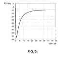
- FIG. 2 a schematic diagram of an example of a power spectrum of a received signal comprising coupled in a reference signal is shown.
- the diagram schematically shows a power ratio P measured in dBm, i.e. the power ratio in decibels (dB) of the measured power referenced to one milliwatt over frequency f (measured in Hertz) of the output intermediate frequency of a receiver circuit.
- the spectrum of the signal corresponding to the signal received on the antenna may have a maximum bandwidth 62.
- the upconversion mixer 38 may be configured to generate the upconverted reference signal having a frequency value outside of a frequency range of the third plurality of received signals. This may result in having the reference or test signal 64 in the power spectrum of the output signal close to but without interfering with the antenna signal spectrum.
- the reference signal 42 applied to the upconversion mixer 38 may for example be genererated externally.
- the multichannel receiver system 10 may comprise a frequency divider circuit (not shown) having a frequency divider input connected to the local oscillator 28 and a frequency divider output connected to the first mixer input 40.
- the frequency divider which may for example be implemented as a frequency divider chain, may generate the low-frequency reference signal 42 from the local oscillator 28 signal.
- the multichannel receiver system 10 may be implemented as a monolithic integrated circuit, for example as a monolithic microwave integrated circuit (MMIC).
- MMIC monolithic microwave integrated circuit
- Using one multichannel receiver die may allow to reduce phase shifts introduced by the receiving paths, since hardware variations between receiving paths due to production variation and signal interference due to coupling of separate circuits may be reduced.
- a power of the reference signal may be below a compression point of the mixer 38, avoiding distortions introduced by the mixer.
- the 1 dB compression point of the mixer 38 may be the upper threshold of a dynamic range of the mixer, which may also be a signal amplifier.
- the power of the reference signal may be at most 10 dB below the 1 dB compression point of the mixer 38.
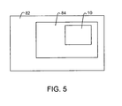
- FIG. 3 a schematic diagram of an example of a phase difference PD versus sideband suppression ratio SSR is shown.
- the shown diagram may apply to a dual channel receiver system as shown in FIG. 1 , wherein for example both receive circuits 12, 14 may receive signals, each comprising the reference signal, but introduce phase shifts that differ by 10°.
- the phase difference PD in degree between a first and a second intermediate frequency output signal 34, 36 delivered by the first and second receiver circuit 12, 14 is shown over a variable sideband suppression ratio SSR in decibel (dB) achieved by the upconversion mixer.
- dB decibel
- the upconversion mixer may be configured to apply an IQ phase variation to the reference signal, i.e. a phase variation of the in-phase or the quadrature phase component of the reference signal which may further increase the sideband suppression ratio SSR.
- the shown multichannel receiver system may comprise a peak detector circuit 52 connected to the mixer output 46.
- the peak detector circuit 52 may determine a maximum power of the upconverted reference signal.
- a gain of the particular receiving path may be determined allowing for accurate comparison of gains of particular receiving paths and automatic gain calibration, i.e. relating the amplitude of the reference signal before coupling into a receiving path or channel and the amplitude of the reference signal comprised in the output signal of the receiving path may allow for eliminating or at least reducing changes in conversion gain.
- Phase monitoring may be performed for example by a processor, e.g. outside of the multichannel receiver system 10, the processor receiving the output signals 34, 36.
- the multichannel receiver system 10 may comprise a phase monitoring module 54 connected to receive at least two of the fourth plurality of output signals 34, 36 and provide at least a difference phase value.
- the phase monitoring module 54 may determine a phase of an output signal 34, 36 comprising a phase shift introduced by the receiving path.
- a relative phase shift of the reference signal and therefore of the received signal may be determined and be used for calibration of the particular receiving path. This calibration may, as well as the monitoring process be performed in-situ during regular operation without switching the system 10 or the receiving path in a calibration mode, which may for example interrupt or at least disturb receive operation of the system 10.
- the system 10 may be able to introduce the same or at least very similar phase shift to the received signals, therefore allowing for high-resolution determination of relative phase differences or phase variations between signals received on different signal paths, which may for example allow for an accurate determination of the angle-of-arrival of the main lobe of the signal being received.
- the multichannel receiver system 10 may comprise a gain monitoring module 56 connected to receive a value corresponding to a power of the upconverted reference signal and to receive at least one of the fourth plurality of output signals 34, 36 and provide a gain value for the at least one of the fourth plurality of output signals 34, 36.
- the gain monitoring module 56 may be configured to determine a gain between the upconverted reference signal and the reference signal part comprised in the receiver output signals 34, 36, therefore allowing to detect and compensate gain variations of a receiving path and between receiving paths.
- the system 10 may comprise a phase monitoring module 54 and a gain monitoring module 56 combined in a phase and gain monitoring module or circuit 54, 56.
- the method for multichannel receiver monitoring may comprise receiving 66 each of a first plurality of received signals on a corresponding first input of a corresponding one of a second plurality of receiver circuits connected to a corresponding one of a third plurality of input lines; receiving 68 a reference signal on a first mixer input of an upconversion mixer; receiving 70 a local oscillator signal on a corresponding second input of a corresponding one of the second plurality of receiver circuits and on a second input of the upconversion mixer; providing 72 an upconverted reference signal on an output of the upconversion mixer; coupling 74 the upconverted reference signal into the first plurality of received signals using a fourth plurality of directional couplers; providing 76 each of a fifth plurality of downconverted output signals on a corresponding output of a corresponding one of the second plurality of receiver circuits; generating 78 a difference phase value for
- the described method may allow implementing the advantages and characteristics of the described multichannel receiver system as part of a method for multichannel receiver monitoring.
- the method for multichannel receciver monitoring may be a method for phase and gain monitoring and may comprise receiving a value corresponding to a power of the upconverted reference signal; receiving at least one of the fifth plurality of output signals and generating a gain value for the at least one of the fifth plurality of output signals.
- a radar system 84 may comprise a multichannel receiver system 10 or may execute steps of a method as described above.
- the radar system 84 may be implemented based on for example a 77 GHz radar chipset.
- the radar system 84 may be an automotive radar system. Radar technology may for example be used for road safety applications such as Adaptive Cruise Control (ACC) 'long-range radar', which may for example operate at 77 GHz. This may enable a vehicle to maintain a cruising distance from a vehicle in front.
- ACC Adaptive Cruise Control
- radar may also be used for anti-collision 'short-range radar' operating for example in a range of 24 GHz, 26 GHz or 79 GHz.
- radar may be part of a system for warning a driver of a pending collision, enabling avoiding action to be taken.
- the vehicle may prepare itself, for example by applying brakes, pretensioning seat belts etc., for reducing injury to passengers and others.
- the presented system may be applied to applications using any other frequency range, for example other mm-wave applications, e.g. working at 122 GHz or using a wireless personal area network
- WPAN wireless personal area network
- the vehicle 82 may comprise a radar system 84 or a multichannel receiver system 10 as described above.
- a vehicle 82 may be a car. However, it may be any automotive apparatus, such as a plane, a ship, a helicopter etc.
- a computer program product may comprise code portions for executing steps of a method or for implementing parts of a multichannel receiver system as described above when run on a programmable apparatus.
- the invention may for example at least partly be implemented in a computer program for running on a computer system, at least including code portions for performing steps of a method according to the invention when run on a programmable apparatus, such as a computer system or enabling a programmable apparatus to perform functions of a device or system according to the invention.
- the computer program may for instance include one or more of: a subroutine, a function, a procedure, an object method, an object implementation, an executable application, an applet, a servlet, a source code, an object code, a shared library/dynamic load library and/or other sequence of instructions designed for execution on a computer system.
- the computer program may be provided on a data carrier, such as a CD-rom or diskette, stored with data loadable in a memory of a computer system, the data representing the computer program.
- the data carrier may further be a data connection, such as a telephone cable or a wireless connection.
- connections may be any type of connection suitable to transfer signals from or to the respective nodes, units or devices, for example via intermediate devices. Accordingly, unless implied or stated otherwise the connections may for example be direct connections or indirect connections.
- FIG. 1 and the discussion thereof describe an exemplary system
- this exemplary system is presented merely to provide a useful reference in discussing various aspects of the invention.
- the description has been simplified for purposes of discussion, and it is just one of many different types of appropriate architectures that may be used in accordance with the invention.
- Those skilled in the art will recognize that the boundaries between logic blocks are merely illustrative and that alternative embodiments may merge logic blocks or impose an alternate decomposition of functionality upon various logic blocks.
- any two components herein combined to achieve a particular functionality can be seen as “associated with” each other such that the desired functionality is achieved, irrespective of architectures or intermedial components.
- any two components so associated can also be viewed as being “operably connected,” or “operably coupled,” to each other to achieve the desired functionality.
- the invention is not limited to physical devices or units implemented in non-programmable hardware but can also be applied in programmable devices or units able to perform the desired device functions by operating in accordance with suitable program code.
- the programmable apparatus may for example comprise a processing device or processing unit being one or more of a group consisting of: microprocessor, central processing unit, a graphics processor, coprocessor, digital signal processor, embedded processor application specific integrated circuit (ASIC), field programmable gate array (FPGA), programmable logic array (PLA), a device implementing a state machine, a microcontroller unit (MCU).
- the devices may be physically distributed over a number of apparatuses, while functionally operating as a single device.
- the multichannel receiver system 10 may comprise a local oscillator module.
- the local oscillator signal may be received from an oscillator being connected to the receiver system 10.
- the monitoring module 54, 56 may be a part of system 10 or may at least partly be comprised in a programmable apparatus for example being a computer system.
- Computer systems are information handling systems which can be designed to give independent computing power to one or more users.
- Computer systems may be found in many forms including but not limited to mainframes, minicomputers, servers, workstations, personal computers, notepads, personal digital assistants, electronic games, automotive and other embedded systems, cell phones and various other wireless devices.
- system 10 or portions thereof may be soft or code representations of physical circuitry or of logical representations convertible into physical circuitry.
- system 10 may be embodied in a hardware description language of any appropriate type.
- any reference signs placed between parentheses shall not be construed as limiting the claim.
- the word 'comprising' does not exclude the presence of other elements or steps then those listed in a claim.
- the terms "a” or "an,” as used herein, are defined as one or more than one.
Landscapes
- Engineering & Computer Science (AREA)
- Radar, Positioning & Navigation (AREA)
- Remote Sensing (AREA)
- Physics & Mathematics (AREA)
- Computer Networks & Wireless Communication (AREA)
- General Physics & Mathematics (AREA)
- Electromagnetism (AREA)
- Radar Systems Or Details Thereof (AREA)
- Radio Transmission System (AREA)
Claims (14)
- Système récepteur multicanal (10), comprenant :une première pluralité de circuits récepteurs (12, 14), chaque circuit récepteur (12, 14) comportant :une première entrée (16, 18) connectée à une ligne d'entrée correspondante parmi une deuxième pluralité de lignes d'entrée (20, 22), chaque ligne d'entrée étant agencée pour fournir un signal reçu correspondant parmi une troisième pluralité de signaux reçus ;une deuxième entrée (24, 26) connectée à un oscillateur local (28) agencé pour fournir un signal d'oscillateur local ; etune sortie (30, 32) agencée pour fournir un signal de sortie correspondant parmi une quatrième pluralité de signaux de sortie (34, 36) ; etun mélangeur élévateur de fréquence (38) comportant :une première entrée de mélangeur (40) destinée à recevoir un signal de référence (42) ;une deuxième entrée de mélangeur (44) connectée audit oscillateur local (28) ;
etune sortie de mélangeur (46) fournissant un signal de référence (64) de fréquence augmentée à :une cinquième pluralité de coupleurs directionnels (48, 50), chaque coupleur directionnel (48, 50) étant connecté à une ligne d'entrée correspondante de ladite deuxième pluralité de lignes d'entrée (20, 22) ;caractérisé en ce que ledit mélangeur élévateur de fréquence (38) est configuré pour générer ledit signal de référence (64) de fréquence augmentée ayant une valeur de fréquence située en dehors d'une plage de fréquences (62) de ladite troisième pluralité de signaux reçus. - Système récepteur multicanal (10) tel que revendiqué dans la revendication 1, dans lequel ledit mélangeur élévateur de fréquence (38) est un mélangeur à bande latérale unique.
- Système récepteur multicanal (10) tel que revendiqué dans la revendication 1 ou la revendication 2, dans lequel ledit mélangeur élévateur de fréquence (38) est configuré pour supprimer ledit signal d'oscillateur local dans ledit signal de référence (64) de fréquence augmentée.
- Système récepteur multicanal (10) tel que revendiqué dans l'une quelconque des revendications précédentes, comprenant un circuit diviseur de fréquence comportant une entrée de diviseur de fréquence connectée audit oscillateur local (28) et une sortie de diviseur de fréquence connectée à ladite première entrée de mélangeur (40).
- Système récepteur multicanal (10) tel que revendiqué dans l'une quelconque des revendications précédentes, dans lequel une puissance dudit signal de référence (64) est située au-dessous d'un point de compression dudit mélangeur (38).
- Système récepteur multicanal (10) tel que revendiqué dans l'une quelconque des revendications précédentes, ledit système récepteur multicanal (10) étant réalisé en tant que circuit intégré monolithique.
- Système récepteur multicanal (10) tel que revendiqué dans l'une quelconque des revendications précédentes, comprenant un circuit de détection de crête (52) connecté à ladite sortie de mélangeur (46).
- Système récepteur multicanal (10) tel que revendiqué dans l'une quelconque des revendications précédentes, comprenant un module de contrôle de phase (54) connecté de manière à recevoir au moins deux signaux de sortie de ladite quatrième pluralité de signaux de sortie et à fournir au moins une valeur de phase de différence.
- Système récepteur multicanal (10) tel que revendiqué dans l'une quelconque des revendications précédentes, comprenant un module de contrôle de gain (56) connecté de manière à recevoir une valeur correspondant à une puissance dudit signal de référence de fréquence augmentée et à recevoir au moins l'un des signaux de sortie de ladite quatrième pluralité de signaux de sortie, et à fournir une valeur de gain pour ledit au moins l'un des signaux de sortie de ladite quatrième pluralité de signaux de sortie.
- Procédé de contrôle d'un récepteur multicanal, comprenant :la réception (66) de chacun d'une première pluralité de signaux reçus sur une première entrée correspondante (16, 18) d'un circuit récepteur correspondant parmi une deuxième pluralité de circuits récepteurs (12, 14) connectés à une ligne d'entrée correspondante parmi une troisième pluralité de lignes d'entrée (20, 22) ;la réception (68) d'un signal de référence sur une première entrée de mélangeur (40) d'un mélangeur élévateur de fréquence (38) ;la réception (70) d'un signal d'oscillateur local sur une deuxième entrée correspondante (24, 26) d'un circuit récepteur correspondant de ladite deuxième pluralité de circuits récepteurs (12, 14) et sur une deuxième entrée (44) dudit mélangeur élévateur de fréquence (38) ;la fourniture (72) d'un signal de référence (64) de fréquence augmentée sur une sortie (46) dudit mélangeur élévateur de fréquence (38) ;le couplage (74) dudit signal de référence (64) de fréquence augmentée et de ladite première pluralité de signaux reçus en utilisant une quatrième pluralité de coupleurs directionnels (48, 50) ;la fourniture (76) de chacun d'une cinquième pluralité de signaux de sortie (34, 36) de fréquence diminuée sur une sortie correspondante (30, 32) d'un circuit récepteur correspondant de ladite deuxième pluralité de circuits récepteurs (12, 14) ;la génération (78) d'une valeur de phase de différence pour au moins deux desdits signaux de sortie (34, 36) de fréquence diminuée comprenant le signal de référence de fréquence diminuée ; etla détermination (80) d'une variation de phase entre lesdites valeurs de phase de différence ;caractérisé en ce que ledit mélangeur élévateur de fréquence (38) est configuré pour générer ledit signal de référence (64) de fréquence augmentée ayant une valeur de fréquence située en dehors d'une plage de fréquences (62) de ladite troisième pluralité de signaux reçus.
- Procédé tel que revendiqué dans la revendication 10, comprenant :la réception d'une valeur correspondant à une puissance dudit signal de référence (64) de fréquence augmentée ;la réception d'au moins un signal de sortie de ladite cinquième pluralité de signaux de sortie ; etla génération d'une valeur de gain pour ledit au moins un signal de sortie de ladite cinquième pluralité de signaux de sortie.
- Système radar (84), comprenant un système récepteur multicanal (10) tel que revendiqué dans l'une quelconque des revendications 1 à 9 ou exécutant des étapes d'un procédé tel que revendiqué dans la revendication 10 ou la revendication 11.
- Véhicule (82), comprenant un système radar (84) tel que revendiqué dans la revendication 12 ou un système récepteur multicanal (10) tel que revendiqué dans l'une quelconque des revendications 1 à 9.
- Produit programme d'ordinateur, comprenant des portions de code destinées à exécuter des étapes d'un procédé tel que revendiqué dans la revendication 10 ou la revendication 11 ou destinées à la mise en oeuvre de parties d'un système récepteur multicanal (10) tel que revendiqué dans l'une quelconque des revendications 1 à 9 lorsqu'elles sont exécutées sur un appareil programmable.
Priority Applications (2)
| Application Number | Priority Date | Filing Date | Title |
|---|---|---|---|
| EP13167459.0A EP2654212B1 (fr) | 2009-06-29 | 2009-06-29 | Système récepteur multicanal et procédé de surveillance de récepteur multicanal |
| EP13167454.1A EP2654211B1 (fr) | 2009-06-29 | 2009-06-29 | Système récepteur multicanal et procédé de surveillance de récepteur multicanal |
Applications Claiming Priority (1)
| Application Number | Priority Date | Filing Date | Title |
|---|---|---|---|
| PCT/IB2009/052803 WO2011001206A1 (fr) | 2009-06-29 | 2009-06-29 | Système récepteur multicanal et procédé de surveillance de récepteur multicanal |
Related Child Applications (4)
| Application Number | Title | Priority Date | Filing Date |
|---|---|---|---|
| EP13167454.1A Division EP2654211B1 (fr) | 2009-06-29 | 2009-06-29 | Système récepteur multicanal et procédé de surveillance de récepteur multicanal |
| EP13167459.0A Division EP2654212B1 (fr) | 2009-06-29 | 2009-06-29 | Système récepteur multicanal et procédé de surveillance de récepteur multicanal |
| EP13167459.0 Division-Into | 2013-05-13 | ||
| EP13167454.1 Division-Into | 2013-05-13 |
Publications (3)
| Publication Number | Publication Date |
|---|---|
| EP2449685A1 EP2449685A1 (fr) | 2012-05-09 |
| EP2449685A4 EP2449685A4 (fr) | 2013-01-16 |
| EP2449685B1 true EP2449685B1 (fr) | 2013-10-23 |
Family
ID=43410539
Family Applications (3)
| Application Number | Title | Priority Date | Filing Date |
|---|---|---|---|
| EP09846744.2A Active EP2449685B1 (fr) | 2009-06-29 | 2009-06-29 | Système récepteur multicanal et procédé de surveillance de récepteur multicanal |
| EP13167459.0A Active EP2654212B1 (fr) | 2009-06-29 | 2009-06-29 | Système récepteur multicanal et procédé de surveillance de récepteur multicanal |
| EP13167454.1A Active EP2654211B1 (fr) | 2009-06-29 | 2009-06-29 | Système récepteur multicanal et procédé de surveillance de récepteur multicanal |
Family Applications After (2)
| Application Number | Title | Priority Date | Filing Date |
|---|---|---|---|
| EP13167459.0A Active EP2654212B1 (fr) | 2009-06-29 | 2009-06-29 | Système récepteur multicanal et procédé de surveillance de récepteur multicanal |
| EP13167454.1A Active EP2654211B1 (fr) | 2009-06-29 | 2009-06-29 | Système récepteur multicanal et procédé de surveillance de récepteur multicanal |
Country Status (5)
| Country | Link |
|---|---|
| US (1) | US8620248B2 (fr) |
| EP (3) | EP2449685B1 (fr) |
| JP (1) | JP5537654B2 (fr) |
| CN (1) | CN102449914B (fr) |
| WO (1) | WO2011001206A1 (fr) |
Families Citing this family (22)
| Publication number | Priority date | Publication date | Assignee | Title |
|---|---|---|---|---|
| DE102010012624A1 (de) * | 2010-03-24 | 2011-09-29 | Valeo Schalter Und Sensoren Gmbh | Fahrerassistenzeinrichtung für ein Fahrzeug und Verfahren zum Betreiben eines Radargeräts |
| CN103329004B (zh) * | 2011-01-21 | 2017-07-28 | 飞思卡尔半导体公司 | 相控阵接收器、雷达系统以及运载工具 |
| DE102011012843A1 (de) | 2011-03-03 | 2012-09-06 | Valeo Schalter Und Sensoren Gmbh | Fahrerassistenzeinrichtung für ein Fahrzeug und Verfahren zum Betreiben eines Radargeräts |
| US8634850B2 (en) | 2011-03-11 | 2014-01-21 | Qualcomm Incorporated | Providing wireless transmitter almanac information to mobile station based on expected contribution to future navigation operation |
| DE102011115309A1 (de) | 2011-09-29 | 2013-04-04 | Infineon Technologies Ag | Radarschaltung, Radarsystem und Verfahren zum Testen einer Verbindung zwischen einer Radarschaltung und einer Radarantenne in einem Fahrzeug |
| JP5861396B2 (ja) * | 2011-11-02 | 2016-02-16 | トヨタ自動車株式会社 | 車両用歩行者検知装置、車両用歩行者保護システム |
| DE102012015250A1 (de) | 2012-08-01 | 2014-02-06 | Audi Ag | Radarsensor für ein Kraftfahrzeug, Kraftfahrzeug und Kommunikationsverfahren |
| EP2799898B1 (fr) * | 2013-05-02 | 2019-07-10 | LEONARDO Germany GmbH | Radar météorologique |
| DE102013009670B4 (de) * | 2013-06-08 | 2016-01-07 | Audi Ag | Bewerten und Akustisches Aussenden von Hörfunksignalen in einem Fahrzeug |
| JP6376901B2 (ja) * | 2014-08-26 | 2018-08-22 | 株式会社デンソーテン | 受信信号処理装置、レーダ装置、および物標検知方法 |
| EP3228014B1 (fr) * | 2014-12-05 | 2020-02-05 | Murata Manufacturing Co., Ltd. | Système, procédé et module de couverture de signaux rf pour véhicules automobiles |
| RU2587161C1 (ru) * | 2015-07-01 | 2016-06-20 | Федеральное государственное казенное военное образовательное учреждение высшего профессионального образования "Военная академия воздушно-космической обороны имени Маршала Советского Союза Г.К. Жукова" Министерства обороны Российской Федерации | Комплексное устройство обнаружения |
| GB201602524D0 (en) * | 2016-02-12 | 2016-03-30 | Filtronic Broadband Ltd | A millimetre wave transceiver |
| RU2608556C1 (ru) * | 2016-02-19 | 2017-01-23 | Федеральное государственное казенное военное образовательное учреждение высшего образования "Военная академия воздушно-космической обороны имени Маршала Советского Союза Г.К. Жукова" Министерства обороны Российской Федерации | Комплексная система обнаружения в многопозиционной радиолокационной станции |
| EP3327961B1 (fr) | 2016-11-28 | 2019-11-06 | Nxp B.V. | Test de récepteur |
| DE102017119212A1 (de) | 2016-12-20 | 2018-06-21 | Infineon Technologies Ag | HF-Transceiver mit Testmöglichkeit |
| US10530623B2 (en) * | 2017-07-14 | 2020-01-07 | Qualcomm Incorporated | Reference signal design |
| WO2019035348A1 (fr) * | 2017-08-18 | 2019-02-21 | 古野電気株式会社 | Dispositif radar et procédé de modification du gain de réception d'un dispositif radar |
| US11047973B2 (en) * | 2018-09-10 | 2021-06-29 | GM Global Technology Operations LLC | Ultra-wide band radar calibration and angle of arrival estimation |
| DE102019201605B3 (de) * | 2019-02-07 | 2020-04-23 | Audi Ag | Verfahren zum Betreiben einer Medienwiedergabevorrichtung sowie Medienwiedergabevorrichtung |
| JP7211303B2 (ja) * | 2019-08-26 | 2023-01-24 | 株式会社デンソー | 自己診断装置 |
| DE102020109611B4 (de) * | 2020-04-07 | 2022-01-05 | Infineon Technologies Ag | Radarsystem mit balancing der empfangskanäle über mehrere radar-chips |
Family Cites Families (14)
| Publication number | Priority date | Publication date | Assignee | Title |
|---|---|---|---|---|
| US3471855A (en) | 1968-11-25 | 1969-10-07 | Us Air Force | System for generating test signals for an array of receiver channels |
| US3883870A (en) | 1973-12-17 | 1975-05-13 | Hughes Aircraft Co | System for phase aligning parallel signal processing channels |
| FR2408149A1 (fr) * | 1977-11-08 | 1979-06-01 | Thomson Csf | Equipement radar a onde continue |
| NL7902974A (nl) | 1979-04-17 | 1980-10-21 | Hollandse Signaalapparaten Bv | Monopulsradarapparaat met piloottoongenerator. |
| JPS61108984A (ja) * | 1984-11-01 | 1986-05-27 | Toshiba Corp | モノパルス測角レ−ダ装置 |
| US4984293A (en) | 1989-10-17 | 1991-01-08 | Rockwell International Corporation | Multi-channel microwave receiver having self-test capability |
| US5237332A (en) | 1992-02-25 | 1993-08-17 | Hughes Aircraft Company | Receiver distortion correction circuit and method |
| US5867123A (en) | 1997-06-19 | 1999-02-02 | Motorola, Inc. | Phased array radio frequency (RF) built-in-test equipment (BITE) apparatus and method of operation therefor |
| US6208287B1 (en) | 1998-03-16 | 2001-03-27 | Raytheoncompany | Phased array antenna calibration system and method |
| GB0018746D0 (en) * | 2000-07-31 | 2000-09-20 | Nokia Networks Oy | Calibration apparatus and method for use with an antenna array |
| JP2005159587A (ja) * | 2003-11-21 | 2005-06-16 | Akihiko Yonetani | 偶高調波ミキサ |
| JP2006003303A (ja) * | 2004-06-21 | 2006-01-05 | Fujitsu Ten Ltd | レーダ装置 |
| JP4665676B2 (ja) | 2005-09-09 | 2011-04-06 | パナソニック株式会社 | 受信装置 |
| US20080096509A1 (en) | 2006-10-19 | 2008-04-24 | Maxlinear, Inc. | Low Complexity Diversity Receiver |
-
2009
- 2009-06-29 EP EP09846744.2A patent/EP2449685B1/fr active Active
- 2009-06-29 JP JP2012516876A patent/JP5537654B2/ja active Active
- 2009-06-29 CN CN200980159640.4A patent/CN102449914B/zh active Active
- 2009-06-29 EP EP13167459.0A patent/EP2654212B1/fr active Active
- 2009-06-29 US US13/322,942 patent/US8620248B2/en active Active
- 2009-06-29 WO PCT/IB2009/052803 patent/WO2011001206A1/fr not_active Ceased
- 2009-06-29 EP EP13167454.1A patent/EP2654211B1/fr active Active
Also Published As
| Publication number | Publication date |
|---|---|
| CN102449914A (zh) | 2012-05-09 |
| US8620248B2 (en) | 2013-12-31 |
| EP2654212A1 (fr) | 2013-10-23 |
| EP2654211A1 (fr) | 2013-10-23 |
| JP5537654B2 (ja) | 2014-07-02 |
| US20120088464A1 (en) | 2012-04-12 |
| EP2449685A1 (fr) | 2012-05-09 |
| EP2449685A4 (fr) | 2013-01-16 |
| EP2654211B1 (fr) | 2017-03-01 |
| WO2011001206A1 (fr) | 2011-01-06 |
| CN102449914B (zh) | 2014-11-26 |
| JP2012532311A (ja) | 2012-12-13 |
| EP2654212B1 (fr) | 2017-03-01 |
Similar Documents
| Publication | Publication Date | Title |
|---|---|---|
| EP2449685B1 (fr) | Système récepteur multicanal et procédé de surveillance de récepteur multicanal | |
| US9817106B2 (en) | Phased-array transmitter, transceiver, and radar apparatus | |
| US11914069B2 (en) | System and MMIC architecture for coherent multi-chip phased array MIMO applications | |
| US20140197983A1 (en) | Receiver device, multi-frequency radar system and vehicle | |
| JP2567332B2 (ja) | 時分割型レーダシステム | |
| US7450056B2 (en) | Search/detection apparatus | |
| US9482745B2 (en) | Driver assistance device for a vehicle and method for operating a radar device | |
| US20210072349A1 (en) | Monitoring an fmcw radar sensor | |
| US9176228B2 (en) | Driver assistance device for a vehicle and method for operating a radar device | |
| JP2004512543A (ja) | レーダ装置およびレーダ装置の駆動方法 | |
| CN119199825A (zh) | 目标检测方法、电子设备及存储介质 | |
| EP1795914B1 (fr) | Module émetteur récepteur et radar FMCW millimétrique utilisant ce module | |
| US10979150B2 (en) | Method of testing RF integrated circuit | |
| EP2555010B1 (fr) | Radar pulsé embarqué dans une voiture | |
| US7495603B2 (en) | Radar apparatus | |
| US20120182177A1 (en) | Mixer monitoring | |
| JP2025073441A (ja) | レーダ装置 | |
| JPH08262133A (ja) | 時分割型レーダシステム | |
| WO2024113318A1 (fr) | Système de traitement de signal et dispositif associé | |
| CN117907947A (zh) | 一种用于发射机的方法、发射机、雷达和终端设备 | |
| Liang et al. | IF amplifier module for high-sweep speed LFMCW radar |
Legal Events
| Date | Code | Title | Description |
|---|---|---|---|
| PUAI | Public reference made under article 153(3) epc to a published international application that has entered the european phase |
Free format text: ORIGINAL CODE: 0009012 |
|
| 17P | Request for examination filed |
Effective date: 20120130 |
|
| AK | Designated contracting states |
Kind code of ref document: A1 Designated state(s): AT BE BG CH CY CZ DE DK EE ES FI FR GB GR HR HU IE IS IT LI LT LU LV MC MK MT NL NO PL PT RO SE SI SK TR |
|
| DAX | Request for extension of the european patent (deleted) | ||
| A4 | Supplementary search report drawn up and despatched |
Effective date: 20121213 |
|
| RIC1 | Information provided on ipc code assigned before grant |
Ipc: G01S 7/40 20060101ALI20121207BHEP Ipc: H04B 1/16 20060101AFI20121207BHEP Ipc: G01S 13/93 20060101ALN20121207BHEP |
|
| GRAP | Despatch of communication of intention to grant a patent |
Free format text: ORIGINAL CODE: EPIDOSNIGR1 |
|
| RIC1 | Information provided on ipc code assigned before grant |
Ipc: G01S 13/93 20060101ALN20130424BHEP Ipc: G01S 3/48 20060101ALI20130424BHEP Ipc: G01S 7/40 20060101ALI20130424BHEP Ipc: H04B 1/16 20060101AFI20130424BHEP |
|
| INTG | Intention to grant announced |
Effective date: 20130517 |
|
| GRAS | Grant fee paid |
Free format text: ORIGINAL CODE: EPIDOSNIGR3 |
|
| GRAA | (expected) grant |
Free format text: ORIGINAL CODE: 0009210 |
|
| AK | Designated contracting states |
Kind code of ref document: B1 Designated state(s): AT BE BG CH CY CZ DE DK EE ES FI FR GB GR HR HU IE IS IT LI LT LU LV MC MK MT NL NO PL PT RO SE SI SK TR |
|
| REG | Reference to a national code |
Ref country code: GB Ref legal event code: FG4D |
|
| REG | Reference to a national code |
Ref country code: CH Ref legal event code: EP |
|
| REG | Reference to a national code |
Ref country code: AT Ref legal event code: REF Ref document number: 638045 Country of ref document: AT Kind code of ref document: T Effective date: 20131115 |
|
| REG | Reference to a national code |
Ref country code: IE Ref legal event code: FG4D |
|
| REG | Reference to a national code |
Ref country code: DE Ref legal event code: R096 Ref document number: 602009019720 Country of ref document: DE Effective date: 20131219 |
|
| REG | Reference to a national code |
Ref country code: NL Ref legal event code: VDEP Effective date: 20131023 |
|
| REG | Reference to a national code |
Ref country code: AT Ref legal event code: MK05 Ref document number: 638045 Country of ref document: AT Kind code of ref document: T Effective date: 20131023 |
|
| REG | Reference to a national code |
Ref country code: LT Ref legal event code: MG4D |
|
| PG25 | Lapsed in a contracting state [announced via postgrant information from national office to epo] |
Ref country code: LT Free format text: LAPSE BECAUSE OF FAILURE TO SUBMIT A TRANSLATION OF THE DESCRIPTION OR TO PAY THE FEE WITHIN THE PRESCRIBED TIME-LIMIT Effective date: 20131023 Ref country code: BE Free format text: LAPSE BECAUSE OF FAILURE TO SUBMIT A TRANSLATION OF THE DESCRIPTION OR TO PAY THE FEE WITHIN THE PRESCRIBED TIME-LIMIT Effective date: 20131023 Ref country code: SE Free format text: LAPSE BECAUSE OF FAILURE TO SUBMIT A TRANSLATION OF THE DESCRIPTION OR TO PAY THE FEE WITHIN THE PRESCRIBED TIME-LIMIT Effective date: 20131023 Ref country code: NL Free format text: LAPSE BECAUSE OF FAILURE TO SUBMIT A TRANSLATION OF THE DESCRIPTION OR TO PAY THE FEE WITHIN THE PRESCRIBED TIME-LIMIT Effective date: 20131023 Ref country code: IS Free format text: LAPSE BECAUSE OF FAILURE TO SUBMIT A TRANSLATION OF THE DESCRIPTION OR TO PAY THE FEE WITHIN THE PRESCRIBED TIME-LIMIT Effective date: 20140223 Ref country code: FI Free format text: LAPSE BECAUSE OF FAILURE TO SUBMIT A TRANSLATION OF THE DESCRIPTION OR TO PAY THE FEE WITHIN THE PRESCRIBED TIME-LIMIT Effective date: 20131023 Ref country code: NO Free format text: LAPSE BECAUSE OF FAILURE TO SUBMIT A TRANSLATION OF THE DESCRIPTION OR TO PAY THE FEE WITHIN THE PRESCRIBED TIME-LIMIT Effective date: 20140123 Ref country code: HR Free format text: LAPSE BECAUSE OF FAILURE TO SUBMIT A TRANSLATION OF THE DESCRIPTION OR TO PAY THE FEE WITHIN THE PRESCRIBED TIME-LIMIT Effective date: 20131023 |
|
| PG25 | Lapsed in a contracting state [announced via postgrant information from national office to epo] |
Ref country code: LV Free format text: LAPSE BECAUSE OF FAILURE TO SUBMIT A TRANSLATION OF THE DESCRIPTION OR TO PAY THE FEE WITHIN THE PRESCRIBED TIME-LIMIT Effective date: 20131023 Ref country code: CY Free format text: LAPSE BECAUSE OF FAILURE TO SUBMIT A TRANSLATION OF THE DESCRIPTION OR TO PAY THE FEE WITHIN THE PRESCRIBED TIME-LIMIT Effective date: 20131023 Ref country code: AT Free format text: LAPSE BECAUSE OF FAILURE TO SUBMIT A TRANSLATION OF THE DESCRIPTION OR TO PAY THE FEE WITHIN THE PRESCRIBED TIME-LIMIT Effective date: 20131023 Ref country code: ES Free format text: LAPSE BECAUSE OF FAILURE TO SUBMIT A TRANSLATION OF THE DESCRIPTION OR TO PAY THE FEE WITHIN THE PRESCRIBED TIME-LIMIT Effective date: 20131023 |
|
| PG25 | Lapsed in a contracting state [announced via postgrant information from national office to epo] |
Ref country code: PT Free format text: LAPSE BECAUSE OF FAILURE TO SUBMIT A TRANSLATION OF THE DESCRIPTION OR TO PAY THE FEE WITHIN THE PRESCRIBED TIME-LIMIT Effective date: 20140224 |
|
| REG | Reference to a national code |
Ref country code: DE Ref legal event code: R097 Ref document number: 602009019720 Country of ref document: DE |
|
| PG25 | Lapsed in a contracting state [announced via postgrant information from national office to epo] |
Ref country code: EE Free format text: LAPSE BECAUSE OF FAILURE TO SUBMIT A TRANSLATION OF THE DESCRIPTION OR TO PAY THE FEE WITHIN THE PRESCRIBED TIME-LIMIT Effective date: 20131023 |
|
| PG25 | Lapsed in a contracting state [announced via postgrant information from national office to epo] |
Ref country code: CZ Free format text: LAPSE BECAUSE OF FAILURE TO SUBMIT A TRANSLATION OF THE DESCRIPTION OR TO PAY THE FEE WITHIN THE PRESCRIBED TIME-LIMIT Effective date: 20131023 Ref country code: RO Free format text: LAPSE BECAUSE OF FAILURE TO SUBMIT A TRANSLATION OF THE DESCRIPTION OR TO PAY THE FEE WITHIN THE PRESCRIBED TIME-LIMIT Effective date: 20131023 Ref country code: SK Free format text: LAPSE BECAUSE OF FAILURE TO SUBMIT A TRANSLATION OF THE DESCRIPTION OR TO PAY THE FEE WITHIN THE PRESCRIBED TIME-LIMIT Effective date: 20131023 Ref country code: PL Free format text: LAPSE BECAUSE OF FAILURE TO SUBMIT A TRANSLATION OF THE DESCRIPTION OR TO PAY THE FEE WITHIN THE PRESCRIBED TIME-LIMIT Effective date: 20131023 Ref country code: IT Free format text: LAPSE BECAUSE OF FAILURE TO SUBMIT A TRANSLATION OF THE DESCRIPTION OR TO PAY THE FEE WITHIN THE PRESCRIBED TIME-LIMIT Effective date: 20131023 |
|
| PLBE | No opposition filed within time limit |
Free format text: ORIGINAL CODE: 0009261 |
|
| STAA | Information on the status of an ep patent application or granted ep patent |
Free format text: STATUS: NO OPPOSITION FILED WITHIN TIME LIMIT |
|
| PG25 | Lapsed in a contracting state [announced via postgrant information from national office to epo] |
Ref country code: DK Free format text: LAPSE BECAUSE OF FAILURE TO SUBMIT A TRANSLATION OF THE DESCRIPTION OR TO PAY THE FEE WITHIN THE PRESCRIBED TIME-LIMIT Effective date: 20131023 |
|
| 26N | No opposition filed |
Effective date: 20140724 |
|
| REG | Reference to a national code |
Ref country code: DE Ref legal event code: R097 Ref document number: 602009019720 Country of ref document: DE Effective date: 20140724 |
|
| PG25 | Lapsed in a contracting state [announced via postgrant information from national office to epo] |
Ref country code: LU Free format text: LAPSE BECAUSE OF FAILURE TO SUBMIT A TRANSLATION OF THE DESCRIPTION OR TO PAY THE FEE WITHIN THE PRESCRIBED TIME-LIMIT Effective date: 20140629 Ref country code: MC Free format text: LAPSE BECAUSE OF FAILURE TO SUBMIT A TRANSLATION OF THE DESCRIPTION OR TO PAY THE FEE WITHIN THE PRESCRIBED TIME-LIMIT Effective date: 20131023 |
|
| REG | Reference to a national code |
Ref country code: CH Ref legal event code: PL |
|
| PG25 | Lapsed in a contracting state [announced via postgrant information from national office to epo] |
Ref country code: SI Free format text: LAPSE BECAUSE OF FAILURE TO SUBMIT A TRANSLATION OF THE DESCRIPTION OR TO PAY THE FEE WITHIN THE PRESCRIBED TIME-LIMIT Effective date: 20131023 |
|
| REG | Reference to a national code |
Ref country code: IE Ref legal event code: MM4A |
|
| PG25 | Lapsed in a contracting state [announced via postgrant information from national office to epo] |
Ref country code: IE Free format text: LAPSE BECAUSE OF NON-PAYMENT OF DUE FEES Effective date: 20140629 Ref country code: LI Free format text: LAPSE BECAUSE OF NON-PAYMENT OF DUE FEES Effective date: 20140630 Ref country code: CH Free format text: LAPSE BECAUSE OF NON-PAYMENT OF DUE FEES Effective date: 20140630 |
|
| PG25 | Lapsed in a contracting state [announced via postgrant information from national office to epo] |
Ref country code: MT Free format text: LAPSE BECAUSE OF FAILURE TO SUBMIT A TRANSLATION OF THE DESCRIPTION OR TO PAY THE FEE WITHIN THE PRESCRIBED TIME-LIMIT Effective date: 20131023 |
|
| REG | Reference to a national code |
Ref country code: FR Ref legal event code: PLFP Year of fee payment: 8 |
|
| PG25 | Lapsed in a contracting state [announced via postgrant information from national office to epo] |
Ref country code: BG Free format text: LAPSE BECAUSE OF FAILURE TO SUBMIT A TRANSLATION OF THE DESCRIPTION OR TO PAY THE FEE WITHIN THE PRESCRIBED TIME-LIMIT Effective date: 20131023 Ref country code: GR Free format text: LAPSE BECAUSE OF FAILURE TO SUBMIT A TRANSLATION OF THE DESCRIPTION OR TO PAY THE FEE WITHIN THE PRESCRIBED TIME-LIMIT Effective date: 20140124 |
|
| PG25 | Lapsed in a contracting state [announced via postgrant information from national office to epo] |
Ref country code: TR Free format text: LAPSE BECAUSE OF FAILURE TO SUBMIT A TRANSLATION OF THE DESCRIPTION OR TO PAY THE FEE WITHIN THE PRESCRIBED TIME-LIMIT Effective date: 20131023 Ref country code: HU Free format text: LAPSE BECAUSE OF FAILURE TO SUBMIT A TRANSLATION OF THE DESCRIPTION OR TO PAY THE FEE WITHIN THE PRESCRIBED TIME-LIMIT; INVALID AB INITIO Effective date: 20090629 |
|
| REG | Reference to a national code |
Ref country code: FR Ref legal event code: PLFP Year of fee payment: 9 |
|
| REG | Reference to a national code |
Ref country code: FR Ref legal event code: TP Owner name: NXP USA, INC., US Effective date: 20170921 |
|
| REG | Reference to a national code |
Ref country code: GB Ref legal event code: 732E Free format text: REGISTERED BETWEEN 20171109 AND 20171115 |
|
| REG | Reference to a national code |
Ref country code: DE Ref legal event code: R081 Ref document number: 602009019720 Country of ref document: DE Owner name: NXP USA, INC. (N.D.GES.D.STAATES DELAWARE), AU, US Free format text: FORMER OWNER: FREESCALE SEMICONDUCTOR, INC., AUSTIN, TEX., US |
|
| REG | Reference to a national code |
Ref country code: FR Ref legal event code: PLFP Year of fee payment: 10 |
|
| PG25 | Lapsed in a contracting state [announced via postgrant information from national office to epo] |
Ref country code: MK Free format text: LAPSE BECAUSE OF FAILURE TO SUBMIT A TRANSLATION OF THE DESCRIPTION OR TO PAY THE FEE WITHIN THE PRESCRIBED TIME-LIMIT Effective date: 20131023 |
|
| P01 | Opt-out of the competence of the unified patent court (upc) registered |
Effective date: 20230725 |
|
| PGFP | Annual fee paid to national office [announced via postgrant information from national office to epo] |
Ref country code: DE Payment date: 20250520 Year of fee payment: 17 |
|
| PGFP | Annual fee paid to national office [announced via postgrant information from national office to epo] |
Ref country code: GB Payment date: 20250520 Year of fee payment: 17 |
|
| PGFP | Annual fee paid to national office [announced via postgrant information from national office to epo] |
Ref country code: FR Payment date: 20250520 Year of fee payment: 17 |