EP2449956A2 - Distale Endkappe für ein Endoskop und Endoskopsystem - Google Patents
Distale Endkappe für ein Endoskop und Endoskopsystem Download PDFInfo
- Publication number
- EP2449956A2 EP2449956A2 EP11187767A EP11187767A EP2449956A2 EP 2449956 A2 EP2449956 A2 EP 2449956A2 EP 11187767 A EP11187767 A EP 11187767A EP 11187767 A EP11187767 A EP 11187767A EP 2449956 A2 EP2449956 A2 EP 2449956A2
- Authority
- EP
- European Patent Office
- Prior art keywords
- distal end
- endoscope
- conduit
- gas
- opening
- Prior art date
- Legal status (The legal status is an assumption and is not a legal conclusion. Google has not performed a legal analysis and makes no representation as to the accuracy of the status listed.)
- Granted
Links
- 238000003780 insertion Methods 0.000 claims abstract description 62
- 230000037431 insertion Effects 0.000 claims abstract description 62
- 239000007921 spray Substances 0.000 claims abstract description 17
- CURLTUGMZLYLDI-UHFFFAOYSA-N Carbon dioxide Chemical compound O=C=O CURLTUGMZLYLDI-UHFFFAOYSA-N 0.000 description 50
- 229910002092 carbon dioxide Inorganic materials 0.000 description 26
- 239000001569 carbon dioxide Substances 0.000 description 24
- XLYOFNOQVPJJNP-UHFFFAOYSA-N water Substances O XLYOFNOQVPJJNP-UHFFFAOYSA-N 0.000 description 20
- 230000000007 visual effect Effects 0.000 description 12
- 239000007788 liquid Substances 0.000 description 11
- 238000011282 treatment Methods 0.000 description 11
- 238000005507 spraying Methods 0.000 description 8
- 210000000683 abdominal cavity Anatomy 0.000 description 7
- 238000005286 illumination Methods 0.000 description 7
- 208000005646 Pneumoperitoneum Diseases 0.000 description 4
- 238000009109 curative therapy Methods 0.000 description 4
- 239000000463 material Substances 0.000 description 4
- 210000002784 stomach Anatomy 0.000 description 4
- 238000005452 bending Methods 0.000 description 3
- 210000001124 body fluid Anatomy 0.000 description 3
- 230000003287 optical effect Effects 0.000 description 3
- 230000008859 change Effects 0.000 description 2
- 238000004140 cleaning Methods 0.000 description 2
- 230000008878 coupling Effects 0.000 description 2
- 238000010168 coupling process Methods 0.000 description 2
- 238000005859 coupling reaction Methods 0.000 description 2
- 239000012530 fluid Substances 0.000 description 2
- 239000013307 optical fiber Substances 0.000 description 2
- 230000001105 regulatory effect Effects 0.000 description 2
- 208000037062 Polyps Diseases 0.000 description 1
- 210000001015 abdomen Anatomy 0.000 description 1
- 230000004075 alteration Effects 0.000 description 1
- 239000000470 constituent Substances 0.000 description 1
- 239000006059 cover glass Substances 0.000 description 1
- 238000003745 diagnosis Methods 0.000 description 1
- 239000003814 drug Substances 0.000 description 1
- 230000009545 invasion Effects 0.000 description 1
- 238000002357 laparoscopic surgery Methods 0.000 description 1
- 238000002350 laparotomy Methods 0.000 description 1
- 210000002429 large intestine Anatomy 0.000 description 1
- 238000012986 modification Methods 0.000 description 1
- 230000004048 modification Effects 0.000 description 1
- 239000011347 resin Substances 0.000 description 1
- 229920005989 resin Polymers 0.000 description 1
- 230000004044 response Effects 0.000 description 1
Images




Classifications
-
- A—HUMAN NECESSITIES
- A61—MEDICAL OR VETERINARY SCIENCE; HYGIENE
- A61B—DIAGNOSIS; SURGERY; IDENTIFICATION
- A61B1/00—Instruments for performing medical examinations of the interior of cavities or tubes of the body by visual or photographical inspection, e.g. endoscopes; Illuminating arrangements therefor
- A61B1/273—Instruments for performing medical examinations of the interior of cavities or tubes of the body by visual or photographical inspection, e.g. endoscopes; Illuminating arrangements therefor for the upper alimentary canal, e.g. oesophagoscopes, gastroscopes
- A61B1/2736—Gastroscopes
-
- A—HUMAN NECESSITIES
- A61—MEDICAL OR VETERINARY SCIENCE; HYGIENE
- A61B—DIAGNOSIS; SURGERY; IDENTIFICATION
- A61B1/00—Instruments for performing medical examinations of the interior of cavities or tubes of the body by visual or photographical inspection, e.g. endoscopes; Illuminating arrangements therefor
- A61B1/00064—Constructional details of the endoscope body
- A61B1/00071—Insertion part of the endoscope body
- A61B1/0008—Insertion part of the endoscope body characterised by distal tip features
- A61B1/00089—Hoods
-
- A—HUMAN NECESSITIES
- A61—MEDICAL OR VETERINARY SCIENCE; HYGIENE
- A61B—DIAGNOSIS; SURGERY; IDENTIFICATION
- A61B1/00—Instruments for performing medical examinations of the interior of cavities or tubes of the body by visual or photographical inspection, e.g. endoscopes; Illuminating arrangements therefor
- A61B1/00064—Constructional details of the endoscope body
- A61B1/00071—Insertion part of the endoscope body
- A61B1/0008—Insertion part of the endoscope body characterised by distal tip features
- A61B1/00101—Insertion part of the endoscope body characterised by distal tip features the distal tip features being detachable
-
- A—HUMAN NECESSITIES
- A61—MEDICAL OR VETERINARY SCIENCE; HYGIENE
- A61B—DIAGNOSIS; SURGERY; IDENTIFICATION
- A61B1/00—Instruments for performing medical examinations of the interior of cavities or tubes of the body by visual or photographical inspection, e.g. endoscopes; Illuminating arrangements therefor
- A61B1/012—Instruments for performing medical examinations of the interior of cavities or tubes of the body by visual or photographical inspection, e.g. endoscopes; Illuminating arrangements therefor characterised by internal passages or accessories therefor
- A61B1/015—Control of fluid supply or evacuation
-
- A—HUMAN NECESSITIES
- A61—MEDICAL OR VETERINARY SCIENCE; HYGIENE
- A61B—DIAGNOSIS; SURGERY; IDENTIFICATION
- A61B1/00—Instruments for performing medical examinations of the interior of cavities or tubes of the body by visual or photographical inspection, e.g. endoscopes; Illuminating arrangements therefor
- A61B1/00112—Connection or coupling means
- A61B1/00119—Tubes or pipes in or with an endoscope
-
- A—HUMAN NECESSITIES
- A61—MEDICAL OR VETERINARY SCIENCE; HYGIENE
- A61B—DIAGNOSIS; SURGERY; IDENTIFICATION
- A61B1/00—Instruments for performing medical examinations of the interior of cavities or tubes of the body by visual or photographical inspection, e.g. endoscopes; Illuminating arrangements therefor
- A61B1/12—Instruments for performing medical examinations of the interior of cavities or tubes of the body by visual or photographical inspection, e.g. endoscopes; Illuminating arrangements therefor with cooling or rinsing arrangements
- A61B1/126—Instruments for performing medical examinations of the interior of cavities or tubes of the body by visual or photographical inspection, e.g. endoscopes; Illuminating arrangements therefor with cooling or rinsing arrangements provided with means for cleaning in-use
Definitions
- the presently disclosed subject matter relates to a distal end hood for an endoscope and an endoscope system. More particularly, the presently disclosed subject matter relates to a distal end hood for an endoscope and an endoscope system in which intraluminal observations and treatments are performed by supplying a constant-pressure gas fed from an gas feed unit into a lumen of a subject being tested through an opening provided at a distal end portion of a flexible endoscope inserted into the lumen.
- an image pickup element such as a CCD (charge-coupled device)
- CCD charge-coupled device
- signal processing is performed using a processor unit to display the image on a monitor.
- a doctor can observe and use this image for diagnosis or inserts a treatment instrument from a treatment instrument insertion channel to perform treatments, such as sample collection and polyp removal.
- a rigid endoscope for observation or a treatment instrument for performing curative treatments is introduced into a body cavity through a plurality of trocars punctured into the abdomen of the patient.
- a pneumoperitoneum unit for supplying a pneumoperitoneum gas into an abdominal cavity is used, in order to secure the visual field of the rigid endoscope and an area for operating treatment instruments.
- a treatment instrument is inserted into a lumen through a forceps channel (treatment instrument channel) of the flexible endoscope to perform curative treatments therein.
- a constant-pressure feed gas such as a carbon dioxide gas, is supplied into the lumen.
- Japanese Patent Application Laid-Open No. 2009-131467 describes a system in which a gas is introduced into a gas feed conduit within a pneumoperitoneum unit from a gas cylinder filled with a CO 2 gas.
- the gas feed conduit is configured so that the CO 2 gas is supplied into an abdominal cavity through an pneumoperitoneum tube introduced into the abdominal cavity by way of a gas feeding guide tube (trocar) punctured into the abdominal cavity of a patient.
- trocar gas feeding guide tube
- Japanese Patent Application Laid-Open No. 2005-287839 describes a system in which a tube for an abdominal cavity and a tube for a lumen are coupled with a gas feed unit, so that a carbon dioxide gas is supplied from the tube for an abdominal cavity into an abdominal cavity through a trocar and that the carbon dioxide gas is supplied from the tube for a lumen into a lumen through a treatment instrument channel.
- Japanese Patent Application Laid-Open No. 2006-280535 describes a system in which a gas is sprayed from a gas/water feed nozzle at a leading end of a gas feed tube to be connected to a gas feed conduit communicated with a cylinder through a coupling member.
- an object of the presently disclosed subject matter is to provide a distal end hood for an endoscope and an endoscope system in which the visual field of an observation window may not be interrupted by bubbles even if the distal end of an endoscope becomes submerged in a liquid, in a constant-pressure gas feed system.
- the first aspect of the presently disclosed subject matter provides a distal end hood for an endoscope to be mounted on a distal end portion of an endoscope including an observation window for making observations within the body of a subject being tested and an opening for spraying a constant-pressure feed gas formed on the distal end surface of the distal end portion, wherein the distal end hood for an endoscope includes a conduit one end opening of which is fitted together by insertion with an opening of the distal end surface and is thus connectable thereto and the other end opening of which is disposed at a position away from the distal end surface toward the proximal end side of the endoscope when the distal end hood for an endoscope is mounted on the distal end portion of the endoscope.
- a constant-pressure feed gas spray port can be disposed away from the distal end surface having the observation window toward the proximal end side of the endoscope. Accordingly, bubbles are prevented from being generated by a sprayed gas and the visual field of the observation window can be secured, even if the distal end portion of the endoscope becomes submerged in a liquid accumulated within a body cavity.
- the second aspect of the presently disclosed subject matter provides the distal end hood for an endoscope characterized in that the other end opening of the conduit is positioned at a flexible portion of the endoscope when the distal end hood for an endoscope is mounted on the distal end portion of the endoscope.
- the third aspect of the presently disclosed subject matter provides the distal end hood for an endoscope characterized in that an O-ring for maintaining airtightness when the one end opening of the conduit is fitted together by insertion with an opening of the distal end surface is provided at one end of the conduit.
- the constant-pressure feed gas can be prevented from leaking at a junction between the opening of the distal end surface and the conduit.
- the fourth aspect of the presently disclosed subject matter provides the distal end hood for an endoscope characterized in that the conduit penetrates through a lateral side of the distal end hood for an endoscope.
- the observation window can be segregated from the surroundings thereof by the distal end hood for an endoscope to secure the visual field of the observation window.
- the fifth aspect of the presently disclosed subject matter provides an endoscope system including: a distal end hood for an endoscope according to any one of the first to fourth aspects; an endoscope including an insertion part to be inserted into an object being examined, a gas feed conduit for supplying a constant-pressure feed gas, and an opening communicated with the gas feed conduit and formed on a distal end surface of the insertion part for spraying the constant-pressure feed gas; and a gas feed unit for supplying the constant-pressure feed gas to the gas feed conduit.
- a constant-pressure feed gas spray port is located away from the distal end surface having the observation window toward the proximal end side of the endoscope. Accordingly, bubbles are prevented from being generated by a sprayed gas and the visual field of the observation window can be secured, even if the distal end portion of the endoscope becomes submerged in a liquid accumulated within a body cavity, thereby enabling accurate observations and the like to be made.
- the sixth aspect of the presently disclosed subject matter provides the endoscope system characterized in that the gas feed conduit for supplying the constant-pressure feed gas is a forceps channel.
- the seventh aspect of the presently disclosed subject matter provides the endoscope system characterized in that the gas feed conduit for supplying the constant-pressure feed gas is a gas feed channel formed within the insertion part.
- the conduit for supplying the constant-pressure feed gas is not limited in particular, but the presently disclosed subject matter is applicable to various types of conduits.
- the constant-pressure feed gas spray port is located away from the distal end surface having the observation window toward the proximal end side of the endoscope. Accordingly, bubbles are prevented from being generated by a sprayed gas and the visual field of the observation window can be secured, even if the distal end portion of the endoscope becomes submerged in a liquid accumulated within a body cavity, thereby enabling accurate observations and the like to be made.
- Fig. 1 is an external view illustrating the schematic overall configuration of a first embodiment of an endoscope system according to the presently disclosed subject matter.
- an endoscope system 1 is equipped with an endoscope gas feed system 2.
- the endoscope system 1 includes an endoscope (flexible endoscope) 10, the endoscope gas feed system 2, a light source unit 100, an endoscope processor 200, and a monitor unit 400.
- the endoscope 10 includes a hand-operated part 12 and an insertion part 14 connected continuously to this hand-operated part 12.
- An operator holds the hand-operated part 12 located on the proximal end side of the endoscope to operate the endoscope 10 and, by inserting the distal end side of the insertion part 14 into a lumen of a subject being tested, the operator can perform observations, diagnoses or curative treatments.
- a universal cable 16 is connected to the hand-operated part 12, and an endoscope connector 18 is provided on the universal cable 16.
- an endoscope connector 18 is provided on the universal cable 16.
- an electrical connector is connected to the endoscope connector 18 through the universal cable 16, and the electrical connector is attachably and detachably coupled with the endoscope processor 200. Consequently, observation image data obtained with the endoscope 10 is output to the endoscope processor 200, so that an observation image is displayed on the monitor unit 400 connected to the endoscope processor 200.
- the hand-operated part 12 is provided with a gas/water feed button 20, a suction button 22, a shutter button 24, a seesaw switch 26 for zooming operation, angle knobs 28, and a forceps insertion part 30.
- the forceps insertion part 30 is communicated with an unillustrated forceps channel formed within the insertion part 14. As will be described later, the forceps channel is communicated with a forceps port (see Fig. 2 ) of the distal end portion of the endoscope.
- a carbon dioxide gas is supplied into a lumen as the constant-pressure feed gas through the forceps channel
- an insertion inlet adapter 34 is provided on the forceps insertion part 30.
- a constant-pressure gas feed tube 32 is coupled with a gas supply cap 36 of the insertion inlet adapter 34.
- the other end of the gas feed tube 32 is coupled with a gas feed unit 300.
- a carbon dioxide gas cylinder 302 is coupled with the gas feed unit 300 through a high-pressure gas tube 304.
- a carbon dioxide gas is stored in a liquefied state in the carbon dioxide gas cylinder 302.
- the carbon dioxide gas stored in the carbon dioxide gas cylinder 302 is introduced from the forceps insertion part 30 to the forceps channel through the gas feed tube 32 by the gas feed unit 300 as a constant-pressure gas regulated to a predetermined pressure, so that the carbon dioxide gas is sprayed into a lumen of a subject being tested from the forceps port of the distal end portion of the endoscope.
- a gas/water feed tube 33 is extended out of the gas feed unit 300 and connected to the endoscope connector 18.
- the gas/water feed tube 33 is communicated with a gas/water feed channel formed within the insertion part 14 of the endoscope through the conduit of the universal cable 16, so that, as will be described later (see Fig. 2 ), a gas supplied by the gas feed unit 300 is sprayed from a gas/water feed nozzle formed on the distal end surface toward the observation window.
- the insertion part 14 includes a flexible portion 38, a bending portion 40, and a distal end portion 42.
- the bending portion 40 is remotely bend-operated by rotating a pair of angle knobs 28 provided on the hand-operated part 12. Consequently, the distal end portion 42 can be directed in a desired direction.
- the flexible portion 38 connects between the hand-operated part 12 and the bending portion 40, and is made of a flexible member, so as to bend in an optional (random) direction along a direction of insertion into the object being examined.
- Fig. 2 illustrates a plan view of a distal end surface 44 of the distal end portion 42 of the insertion part 14.
- an observation window 46, an illumination window 48, a forceps port 50, and a gas/water feed nozzle 52 are disposed on the distal end surface 44 of the distal end portion 42.
- An optical system for capturing image light within an object being examined is disposed at the back of the observation window 46.
- the captured image light representative of an observation image is received by a CCD and sent to the endoscope processor 200 through a signal cable.
- the image light is then converted into a video signal at the endoscope processor 200, so that the observation image is displayed on the monitor unit 400 connected to the endoscope processor 200.
- Two illumination windows 48 are disposed in symmetrical positions on both sides of the observation window 46, as illustrated in Fig. 2 . Illuminating light from the light source unit 100 is irradiated through the illumination windows at an observation site within the object being examined. Light from the light source unit 100 is guided to the illumination windows 48 by an optical fiber (light guide) located within the insertion part 14. Thus, illuminating light is emitted through an illumination lens disposed at a leading end of the optical fiber and a cover glass fitted in each illumination window 48.
- the forceps port 50 is connected to a forceps channel (not illustrated) disposed within the insertion part 14 and communicated with the forceps insertion part 30 of the hand-operated part 12. A leading end of each of forceps and various other treatment instruments inserted into the forceps insertion part 30 is exposed out of the forceps port 50 through the forceps channel.
- a carbon dioxide gas is supplied from the forceps port 50 into a lumen through the forceps channel as the constant-pressure feed gas.
- the insertion inlet adapter 34 is mounted on the forceps insertion part 30, as described above (see Fig. 1 ), so that the carbon dioxide gas is supplied into the lumen from the gas supply cap 36 of the insertion inlet adapter 34 through the gas feed tube 32 coupled with the gas feed unit 300.
- the gas/water feed nozzle 52 is used to clean the observation window 46 by spraying a cleaning fluid and pressurized air when the observation window 46 becomes contaminated.
- the gas/water feed nozzle 52 sprays fluids, such as air and cleaning water, toward the observation window 46 in response to gas feed operation and water feed operation performed by using the gas/water feed button 20 provided on the hand-operated part 12. Consequently, bodily fluids and feculence attached to the observation window 46 are cleaned off and thus an excellent visual field is secured.
- one end opening of a long conduit is connected to the forceps port 50 which is a carbon dioxide gas spray port, this conduit is extended to the proximal end side of the endoscope, and the other end opening of the conduit is located at a position away from the distal end portion 42, thereby spraying a carbon dioxide gas from that position, so that even if bubbles are generated from the carbon dioxide gas sprayed out of the forceps port 50 and from liquids attached to the distal end surface 44, the bubbles do not go into the visual field area of the observation window 46.
- a hood is mounted on the distal end portion 42 in order to connect this conduit (tube) to the forceps port 50.
- the conduit is connected to the forceps port 50 through this hood.
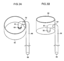
- Figs. 3A and 3B illustrate a distal end hood for an endoscope (hereinafter simply referred to as "hood") according to the presently disclosed subject matter.
- Fig. 3A is a perspective view taken by looking down at the hood from a significantly elevated position
- Fig. 3B is a perspective view taken by looking at the hood from a position lower than the former position.
- a hood 60 is a circular cylinder having a certain thickness, and a thin conduit (tube) 62 bent in an L-shaped manner is disposed inside the hood.
- the conduit 62 is composed of a portion (horizontal portion) substantially perpendicular to a lateral side of the hood 60 and a portion (vertical portion) bent almost 90 degrees from the horizontal portion and parallel to the axial direction of the hood 60. That is, when the hood 60 is mounted on the distal end portion 42 of the endoscope, the horizontal portion of the conduit 62 is perpendicular to the axial direction of the endoscope, and the vertical portion of the conduit 62 is parallel to the axial direction of the endoscope.
- the distal end opening of the vertical portion of the conduit 62 is fitted together by insertion with the forceps port 50 of the distal end surface 44 and is thus connected thereto.
- An edge of a portion of the conduit 62 substantially perpendicular to a lateral side of the hood 60 is connected to an opening 64 formed on the lateral side of the hood 60.
- another conduit 66 connected to the opening 64 is provided external to the opening 64. That is, the conduit 62 and the conduit 66 are formed as one conduit communicated with each other, so as to penetrate through the lateral side of the hood 60.
- the conduit 66 in particular formed external to the opening 64 is preferably a flexible tube formed of a flexible member, such as rubber.
- the conduit 66 formed external to the opening 64 as a flexible tube is longer than the length of the hood 60 along the outer lateral side of the hood 60.
- the conduit 66 is extended in the axial direction thereof, so that a leading end of the conduit 66 reaches the flexible portion 38 when the hood 60 is mounted on the distal end portion 42.
- a distal end opening 68 for spraying a gas is provided at the distal end portion of the conduit 66.
- an edge of the portion of the conduit 62 parallel to the axial direction of the hood 60 extends to a position almost the same as the position of a proximal end side edge of the hood 60.
- An O-ring 69 is disposed at the leading end of the conduit 62.
- conduit 62 internal to the hood 60 and the conduit 66 external to the hood 60 may be formed as separate members.
- the conduits 62 and 66 may be formed of a flexible member, such as rubber, as an integral member.
- a leading end of a tube having a predetermined length may be formed as a portion to serve as the conduit 62, so as to lead the tube from the opening 64 formed on a lateral side of the hood 60 into within the hood 60.
- this tube is too soft, it is difficult to fit the leading end of the tube forming the conduit 62 into the forceps port 50. Accordingly, it is preferable to harden the leading end alone to some degree (it is preferable to make the leading end of the tube harder than the other portion of the tube).
- Fig. 4 perspectively illustrates the hood 60 mounted on the distal end portion 42 of the endoscope 10.
- the hood 60 is mounted in such a manner that the distal end portion 42 is fitted into the inner circumferential surface of the hood 60.
- a mounting part for the hood 60 to be mounted in a state of being externally fitted onto the outer circumferential surface of the distal end portion 42 is formed on the proximal end side (side for the hood to be mounted on the distal end portion 42) of the hood 60.
- a mounting part serving similar to that mounting part of the hood 60 may also be formed in the distal end portion 42.
- the structure of this mounting part is not limited in particular.
- Materials of the hood 60 and the conduit 62 are not limited in particular. Materials of the hood 60 may be resin materials, for example. Alternatively, the conduit 62 may be formed of the same material as that of the conduit 66, so as to be integral therewith.
- the conduit 62 can be fitted into the forceps port 50 while maintaining airtightness, since the O-ring 69 is provided near an edge of the conduit 62, as illustrated in Fig. 3 . Consequently, a carbon dioxide gas is prevented from leaking out of the forceps port 50.
- the other edge (horizontal portion) of the conduit 62 one edge (vertical portion) of which is fitted into the forceps port 50 is coupled with the opening 64 on a lateral side of the hood 60.
- the conduit 62 is connected to the conduit 66 external to the hood 60 through the opening 64.
- the conduit 66 extends along the axial direction of the insertion part 14, the distal end portion of the conduit 66 reaches the flexible portion 38, and the opening 68 for spraying a gas is provided in the distal end portion of the conduit 66.
- one end opening of the conduit 62 is connected to the forceps port 50 which is a constant-pressure feed gas spray port of the distal end surface 44, and the other end opening of the conduit 66 is located far away from the distal end surface 44.
- the conduit 66 is preferably fixed to a lateral side of the insertion part 14, so that when the hood 60 is mounted on the distal end portion 42, the conduit 66 extending to the flexible portion 38 does not freely move away from the insertion part 14. At this time, the conduit 66, even if fixed to a lateral side of the insertion part 14, can change in shape in conformity to the change in shape of the insertion part 14 since the conduit 66 is formed of a flexible member, such as rubber.
- the hood 60 is mounted on the distal end portion 42, the conduit 66 communicated with the forceps port 50 (see Fig. 4 ) is extended to the proximal end side of the insertion part 14, and the opening 68 is provided in a position away from the distal end portion 42 to spray a gas at that position.
- Fig. 5 illustrates a condition in which the insertion part 14 of the endoscope 10 is inserted into a stomach 70 of a subject being tested. As illustrated in Fig. 5 , even if the distal end portion 42 of the insertion part 14 becomes submerged in a liquid accumulated in the stomach 70, the gas spray port does not submerge and bubbles are therefore not generated by the spout of gas.
- the visual field of the observation window 46 of the distal end surface 44 can be prevented from being interrupted by bubbles.
- Fig. 6 is an external view illustrating a schematic overall configuration of a second embodiment of an endoscope system equipped with an endoscope gas feed system according to the presently disclosed subject matter.
- an endoscope system 101 of the present embodiment is equipped with an endoscope gas feed system 102.
- the endoscope system 101 also has a configuration substantially the same as that of the endoscope system 1 of the above-described first embodiment. Accordingly, like constituent elements are denoted by the same reference numerals as those of the endoscope system 1 of the first embodiment and will be described in no further detail.
- the endoscope system 101 includes an endoscope (flexible endoscope) 10, a light source unit 100, an endoscope processor 200 and a monitor unit 400, in addition to the endoscope gas feed system 102.
- the endoscope 10 includes a hand-operated part 12 and an insertion part 14.
- a universal cable 16 is connected to the hand-operated part 12, and an endoscope connector 18 is provided on the universal cable 16.
- the universal cable 16 is connected to the light source unit 100 and the endoscope processor 200 through the endoscope connector 18.
- a constant-pressure feed gas is supplied from a constant-pressure feed gas spray port at the leading end of the insertion part 14 through a constant-pressure gas feed channel separately formed within the insertion part 14, rather than from the forceps port 50.
- the gas feed tube 32 is coupled with the gas supply cap 36 of the insertion inlet adapter 34 provided in the forceps insertion part 30.
- one end of the gas feed tube 32 is coupled with the gas feed unit 300 and the other end thereof is communicated from the endoscope connector 18 through the universal cable 16 to the constant-pressure gas feed channel.
- a carbon dioxide gas cylinder 302 is coupled with the gas feed unit 300 through a high-pressure gas tube 304.
- a carbon dioxide gas is stored in a liquefied state in the carbon dioxide gas cylinder 302.
- the carbon dioxide gas stored in the carbon dioxide gas cylinder 302 is sprayed by the gas feed unit 300, as a constant-pressure gas regulated to a predetermined pressure, out of the spray port of the constant-pressure gas feed channel through the gas feed tube 32 and by way of the endoscope connector 18 through the conduit of the universal cable 16.
- a gas/water feed tube 33 is extended out of the gas feed unit 300 and connected to the endoscope connector 18.
- the gas/water feed tube 33 is communicated with a gas/water feed channel formed within the insertion part 14 of the endoscope through the conduit of the universal cable 16, so that a gas supplied by the gas feed unit 300 is sprayed from a gas/water feed nozzle formed on the distal end surface 44 toward the observation window.
- Fig. 7 illustrates a distal end surface of the distal end portion 42 of the insertion part 14 of the present embodiment.
- a constant-pressure gas feed opening 54 is disposed on the distal end surface 44 of the distal end portion 42, in addition to the observation window 46, the illumination window 48, the forceps port 50, and the gas/water feed nozzle 52.
- the constant-pressure gas feed opening 54 forms a distal end opening of an unillustrated constant-pressure gas feed channel formed within the insertion part 14.
- the constant-pressure gas feed opening 54 is used to spray a constant-pressure feed gas (carbon dioxide gas) supplied from the gas feed unit 300 through the gas feed tube 32, the endoscope connector 18, the conduit of the universal cable 16 and the constant-pressure gas feed channel.
- a constant-pressure feed gas carbon dioxide gas
- Fig. 8 perspectively illustrates the way the hood 60 (see Fig. 3 ) is mounted on the distal end portion 42.
- the hood 60 is mounted in such a manner that the distal end portion 42 is fitted into the inner circumferential surface of the hood 60.
- an edge of a portion (vertical portion) of the L-shaped conduit 62 parallel to the axial direction of the hood 60 is just fitted into (fitted together by insertion with) an inner circumferential surface of the constant-pressure gas feed opening 54 formed on the distal end surface 44 of the distal end portion 42.
- an O-ring for maintaining airtightness is preferably provided in the vertical portion of the conduit 62 to be fitted together by insertion with the inner circumferential surface of the constant-pressure gas feed opening 54.
- an edge of the horizontal portion of the conduit 62 is coupled with an opening 64 on the lateral side of the hood 60.
- the conduit 62 is connected to the conduit 66 external to the hood 60 through the opening 64.
- the conduit 66 extends along the axial direction of the insertion part 14.
- the distal end portion of the conduit 66 reaches the flexible portion 38.
- an opening 68 for spraying a gas is provided in the distal end portion of the conduit 66.
- the conduit 66 is preferably fixed to a lateral side of the insertion part 14, so that when the hood 60 is mounted on the distal end portion 42, the conduit 66 does not move around freely.
- the hood 60 is mounted on the distal end portion 42, the conduit 66 communicated with the constant-pressure gas feed opening 54 is extended to the proximal end side of the insertion part 14, and the opening 68 is provided in a position away from the distal end portion 42 to spray a gas at that position.
- conduit 62 and the conduit 66 penetrate through a lateral side of the hood 60 in either case, so as to communicate with each other.
- the conduit 62 and the conduit 66 are not limited to such a configuration.
- the conduit 62 connected to the opening (the forceps port 50 or the constant-pressure gas feed opening 54) of the distal end surface 44 may be disposed, so as to crawl along the distal end surface 44, and connected to the conduit 66 through the opening 64 formed on the proximal end side of the hood 60.
- the conduit 62 connected to the opening (the forceps port 50 or the constant-pressure gas feed opening 54) of the distal end surface 44 may be formed, so as to extend along the lateral side of the hood 60 to the distal end side thereof and climb over the leading end of the hood 60 to directly connect to the conduit 66.
- a constant-pressure feed gas is sprayed out of a forceps port or the constant-pressure feed gas is supplied through a constant-pressure gas feed channel provided separately from the forceps channel and sprayed out of the distal end opening of the constant-pressure gas feed channel.
- a constant-pressure gas spray port does not submerge in a liquid even if the distal end portion of an endoscope becomes submerged in the liquid, and therefore, bubbles are not generated.
- a gas feed conduit (lumen) for supplying a constant-pressure feed gas is not limited to such a conduit formed within an insertion part as the above-described forceps channel or gas feed channel.
- the conduit may be formed independently of the endoscope.
Landscapes
- Health & Medical Sciences (AREA)
- Life Sciences & Earth Sciences (AREA)
- Surgery (AREA)
- Biomedical Technology (AREA)
- Medical Informatics (AREA)
- Optics & Photonics (AREA)
- Pathology (AREA)
- Radiology & Medical Imaging (AREA)
- Biophysics (AREA)
- Engineering & Computer Science (AREA)
- Physics & Mathematics (AREA)
- Heart & Thoracic Surgery (AREA)
- Nuclear Medicine, Radiotherapy & Molecular Imaging (AREA)
- Molecular Biology (AREA)
- Animal Behavior & Ethology (AREA)
- General Health & Medical Sciences (AREA)
- Public Health (AREA)
- Veterinary Medicine (AREA)
- Gastroenterology & Hepatology (AREA)
- Endoscopes (AREA)
- Instruments For Viewing The Inside Of Hollow Bodies (AREA)
Applications Claiming Priority (1)
| Application Number | Priority Date | Filing Date | Title |
|---|---|---|---|
| JP2010248893A JP5514077B2 (ja) | 2010-11-05 | 2010-11-05 | 内視鏡用先端フード及び内視鏡システム |
Publications (3)
| Publication Number | Publication Date |
|---|---|
| EP2449956A2 true EP2449956A2 (de) | 2012-05-09 |
| EP2449956A3 EP2449956A3 (de) | 2013-09-18 |
| EP2449956B1 EP2449956B1 (de) | 2016-01-13 |
Family
ID=45217186
Family Applications (1)
| Application Number | Title | Priority Date | Filing Date |
|---|---|---|---|
| EP11187767.6A Not-in-force EP2449956B1 (de) | 2010-11-05 | 2011-11-03 | Distale Endkappe für ein Endoskop und Endoskopsystem |
Country Status (3)
| Country | Link |
|---|---|
| US (1) | US8945000B2 (de) |
| EP (1) | EP2449956B1 (de) |
| JP (1) | JP5514077B2 (de) |
Cited By (2)
| Publication number | Priority date | Publication date | Assignee | Title |
|---|---|---|---|---|
| WO2018091645A1 (de) * | 2016-11-17 | 2018-05-24 | Westfälische Wilhelms-Universität Münster | Schutzkappe für eine bildgebende vorrichtung |
| CN112121247A (zh) * | 2020-10-20 | 2020-12-25 | 上海市东方医院(同济大学附属东方医院) | 贲门防撕裂减压装置 |
Families Citing this family (2)
| Publication number | Priority date | Publication date | Assignee | Title |
|---|---|---|---|---|
| US20130018366A1 (en) * | 2011-07-11 | 2013-01-17 | C2 Therapeutics | Focal Ablation Assembly |
| US9763577B2 (en) * | 2013-03-14 | 2017-09-19 | Lumicell, Inc. | Imaging agent for detection of diseased cells |
Citations (3)
| Publication number | Priority date | Publication date | Assignee | Title |
|---|---|---|---|---|
| JP2005287839A (ja) | 2004-03-31 | 2005-10-20 | Olympus Corp | 送気装置及び腹腔鏡下外科手術システム |
| JP2006280535A (ja) | 2005-03-31 | 2006-10-19 | Fujinon Corp | 携帯内視鏡 |
| JP2009131467A (ja) | 2007-11-30 | 2009-06-18 | Olympus Medical Systems Corp | 気腹装置及び気腹システム |
Family Cites Families (16)
| Publication number | Priority date | Publication date | Assignee | Title |
|---|---|---|---|---|
| JPS6015529Y2 (ja) * | 1981-01-16 | 1985-05-16 | オリンパス光学工業株式会社 | 内視鏡 |
| JPS57120004A (en) | 1981-01-17 | 1982-07-26 | Tokyo Shibaura Electric Co | Feed water controller |
| US4735501A (en) * | 1986-04-21 | 1988-04-05 | Identechs Corporation | Method and apparatus for fluid propelled borescopes |
| JPH01229220A (ja) * | 1988-03-09 | 1989-09-12 | Olympus Optical Co Ltd | 内視鏡用ガイドチューブ |
| JPH02139602A (ja) | 1988-11-21 | 1990-05-29 | Mitsubishi Electric Corp | 数値制御装置 |
| JPH0736642Y2 (ja) * | 1989-04-25 | 1995-08-23 | オリンパス光学工業株式会社 | 内視鏡 |
| US5386817A (en) * | 1991-06-10 | 1995-02-07 | Endomedical Technologies, Inc. | Endoscope sheath and valve system |
| DE4220701C2 (de) * | 1991-08-02 | 2001-02-08 | Olympus Optical Co | Reinigungsvorrichtung für ein Endoskop |
| JPH07313443A (ja) * | 1994-05-23 | 1995-12-05 | Olympus Optical Co Ltd | 管内挿入具の挿入装置 |
| JP4533695B2 (ja) * | 2003-09-23 | 2010-09-01 | オリンパス株式会社 | 処置用内視鏡 |
| JP2006325816A (ja) * | 2005-05-25 | 2006-12-07 | Fujinon Corp | 内視鏡用フード |
| KR101326417B1 (ko) * | 2006-01-13 | 2013-11-11 | 올림푸스 메디칼 시스템즈 가부시키가이샤 | 내시경용 오버튜브 |
| US20070163585A1 (en) | 2006-01-13 | 2007-07-19 | Olympus Medical Systems Corp. | Method for accessing abdominal cavity and medical procedure via natural orifice |
| US20090198212A1 (en) * | 2007-05-16 | 2009-08-06 | Tyler Timberlake | Endoscopic injection needle assembly inluding an endoscopic hood |
| WO2009021030A1 (en) * | 2007-08-08 | 2009-02-12 | Wilson-Cook Medical Inc. | Distal tip for an endoscope |
| JP5514075B2 (ja) * | 2010-11-04 | 2014-06-04 | 富士フイルム株式会社 | 内視鏡用アタッチメント及び内視鏡システム |
-
2010
- 2010-11-05 JP JP2010248893A patent/JP5514077B2/ja active Active
-
2011
- 2011-11-03 EP EP11187767.6A patent/EP2449956B1/de not_active Not-in-force
- 2011-11-03 US US13/288,808 patent/US8945000B2/en not_active Expired - Fee Related
Patent Citations (3)
| Publication number | Priority date | Publication date | Assignee | Title |
|---|---|---|---|---|
| JP2005287839A (ja) | 2004-03-31 | 2005-10-20 | Olympus Corp | 送気装置及び腹腔鏡下外科手術システム |
| JP2006280535A (ja) | 2005-03-31 | 2006-10-19 | Fujinon Corp | 携帯内視鏡 |
| JP2009131467A (ja) | 2007-11-30 | 2009-06-18 | Olympus Medical Systems Corp | 気腹装置及び気腹システム |
Cited By (2)
| Publication number | Priority date | Publication date | Assignee | Title |
|---|---|---|---|---|
| WO2018091645A1 (de) * | 2016-11-17 | 2018-05-24 | Westfälische Wilhelms-Universität Münster | Schutzkappe für eine bildgebende vorrichtung |
| CN112121247A (zh) * | 2020-10-20 | 2020-12-25 | 上海市东方医院(同济大学附属东方医院) | 贲门防撕裂减压装置 |
Also Published As
| Publication number | Publication date |
|---|---|
| US20120116165A1 (en) | 2012-05-10 |
| JP5514077B2 (ja) | 2014-06-04 |
| JP2012100684A (ja) | 2012-05-31 |
| US8945000B2 (en) | 2015-02-03 |
| EP2449956A3 (de) | 2013-09-18 |
| EP2449956B1 (de) | 2016-01-13 |
Similar Documents
| Publication | Publication Date | Title |
|---|---|---|
| KR100890094B1 (ko) | 내시경 및 선단 커버 | |
| US11998170B2 (en) | Endoscope | |
| CN110946545B (zh) | 超声波内窥镜 | |
| CN104619265A (zh) | 超声波内窥镜 | |
| US20120253124A1 (en) | Endoscope air-supply system | |
| CN111526798A (zh) | 内窥镜 | |
| EP2449956B1 (de) | Distale Endkappe für ein Endoskop und Endoskopsystem | |
| EP2443987A1 (de) | Endoskop und Endoskopsystem | |
| US20170319175A1 (en) | Ultrasound endoscope and injection tool | |
| US8936547B2 (en) | Endoscope gas feed system, endoscope, and endoscope system | |
| US8939896B2 (en) | Attachment for endoscope and endoscope system | |
| EP3915458A1 (de) | Endoskop mit einer reinigungsanordnung | |
| JP7732888B2 (ja) | 超音波内視鏡 | |
| JPH0724092Y2 (ja) | 超音波内視鏡 | |
| KR102515467B1 (ko) | 탈착형 방사형 주사 초음파 내시경을 구비한 내시경 영상 진단 장치 | |
| JP2020137946A (ja) | 内視鏡 | |
| JPS6075043A (ja) | 超音波診断装置 | |
| JP2018171257A (ja) | 超音波内視鏡および超音波内視鏡用フード | |
| JPH0661203U (ja) | 内視鏡カバー方式の内視鏡装置 | |
| CN120918711A (zh) | 超声波内窥镜 | |
| CN111631673A (zh) | 内窥镜 | |
| JPH03131243A (ja) | 超音波内視鏡 |
Legal Events
| Date | Code | Title | Description |
|---|---|---|---|
| PUAI | Public reference made under article 153(3) epc to a published international application that has entered the european phase |
Free format text: ORIGINAL CODE: 0009012 |
|
| AK | Designated contracting states |
Kind code of ref document: A2 Designated state(s): AL AT BE BG CH CY CZ DE DK EE ES FI FR GB GR HR HU IE IS IT LI LT LU LV MC MK MT NL NO PL PT RO RS SE SI SK SM TR |
|
| AX | Request for extension of the european patent |
Extension state: BA ME |
|
| PUAL | Search report despatched |
Free format text: ORIGINAL CODE: 0009013 |
|
| AK | Designated contracting states |
Kind code of ref document: A3 Designated state(s): AL AT BE BG CH CY CZ DE DK EE ES FI FR GB GR HR HU IE IS IT LI LT LU LV MC MK MT NL NO PL PT RO RS SE SI SK SM TR |
|
| AX | Request for extension of the european patent |
Extension state: BA ME |
|
| RIC1 | Information provided on ipc code assigned before grant |
Ipc: A61B 1/00 20060101ALI20130814BHEP Ipc: A61B 1/313 20060101AFI20130814BHEP |
|
| 17P | Request for examination filed |
Effective date: 20140314 |
|
| RBV | Designated contracting states (corrected) |
Designated state(s): AL AT BE BG CH CY CZ DE DK EE ES FI FR GB GR HR HU IE IS IT LI LT LU LV MC MK MT NL NO PL PT RO RS SE SI SK SM TR |
|
| 17Q | First examination report despatched |
Effective date: 20140618 |
|
| REG | Reference to a national code |
Ref country code: DE Ref legal event code: R079 Ref document number: 602011022593 Country of ref document: DE Free format text: PREVIOUS MAIN CLASS: A61B0001313000 Ipc: A61B0001000000 |
|
| GRAP | Despatch of communication of intention to grant a patent |
Free format text: ORIGINAL CODE: EPIDOSNIGR1 |
|
| RIC1 | Information provided on ipc code assigned before grant |
Ipc: A61B 1/015 20060101ALI20150629BHEP Ipc: A61B 1/273 20060101ALI20150629BHEP Ipc: A61B 1/00 20060101AFI20150629BHEP |
|
| INTG | Intention to grant announced |
Effective date: 20150713 |
|
| GRAS | Grant fee paid |
Free format text: ORIGINAL CODE: EPIDOSNIGR3 |
|
| GRAA | (expected) grant |
Free format text: ORIGINAL CODE: 0009210 |
|
| AK | Designated contracting states |
Kind code of ref document: B1 Designated state(s): AL AT BE BG CH CY CZ DE DK EE ES FI FR GB GR HR HU IE IS IT LI LT LU LV MC MK MT NL NO PL PT RO RS SE SI SK SM TR |
|
| REG | Reference to a national code |
Ref country code: GB Ref legal event code: FG4D |
|
| REG | Reference to a national code |
Ref country code: CH Ref legal event code: EP |
|
| REG | Reference to a national code |
Ref country code: IE Ref legal event code: FG4D |
|
| REG | Reference to a national code |
Ref country code: AT Ref legal event code: REF Ref document number: 769933 Country of ref document: AT Kind code of ref document: T Effective date: 20160215 |
|
| REG | Reference to a national code |
Ref country code: DE Ref legal event code: R096 Ref document number: 602011022593 Country of ref document: DE |
|
| REG | Reference to a national code |
Ref country code: LT Ref legal event code: MG4D |
|
| REG | Reference to a national code |
Ref country code: NL Ref legal event code: MP Effective date: 20160113 |
|
| REG | Reference to a national code |
Ref country code: AT Ref legal event code: MK05 Ref document number: 769933 Country of ref document: AT Kind code of ref document: T Effective date: 20160113 |
|
| PG25 | Lapsed in a contracting state [announced via postgrant information from national office to epo] |
Ref country code: NL Free format text: LAPSE BECAUSE OF FAILURE TO SUBMIT A TRANSLATION OF THE DESCRIPTION OR TO PAY THE FEE WITHIN THE PRESCRIBED TIME-LIMIT Effective date: 20160113 |
|
| PG25 | Lapsed in a contracting state [announced via postgrant information from national office to epo] |
Ref country code: GR Free format text: LAPSE BECAUSE OF FAILURE TO SUBMIT A TRANSLATION OF THE DESCRIPTION OR TO PAY THE FEE WITHIN THE PRESCRIBED TIME-LIMIT Effective date: 20160414 Ref country code: HR Free format text: LAPSE BECAUSE OF FAILURE TO SUBMIT A TRANSLATION OF THE DESCRIPTION OR TO PAY THE FEE WITHIN THE PRESCRIBED TIME-LIMIT Effective date: 20160113 Ref country code: ES Free format text: LAPSE BECAUSE OF FAILURE TO SUBMIT A TRANSLATION OF THE DESCRIPTION OR TO PAY THE FEE WITHIN THE PRESCRIBED TIME-LIMIT Effective date: 20160113 Ref country code: NO Free format text: LAPSE BECAUSE OF FAILURE TO SUBMIT A TRANSLATION OF THE DESCRIPTION OR TO PAY THE FEE WITHIN THE PRESCRIBED TIME-LIMIT Effective date: 20160413 Ref country code: IT Free format text: LAPSE BECAUSE OF FAILURE TO SUBMIT A TRANSLATION OF THE DESCRIPTION OR TO PAY THE FEE WITHIN THE PRESCRIBED TIME-LIMIT Effective date: 20160113 Ref country code: FI Free format text: LAPSE BECAUSE OF FAILURE TO SUBMIT A TRANSLATION OF THE DESCRIPTION OR TO PAY THE FEE WITHIN THE PRESCRIBED TIME-LIMIT Effective date: 20160113 |
|
| PG25 | Lapsed in a contracting state [announced via postgrant information from national office to epo] |
Ref country code: RS Free format text: LAPSE BECAUSE OF FAILURE TO SUBMIT A TRANSLATION OF THE DESCRIPTION OR TO PAY THE FEE WITHIN THE PRESCRIBED TIME-LIMIT Effective date: 20160113 Ref country code: AT Free format text: LAPSE BECAUSE OF FAILURE TO SUBMIT A TRANSLATION OF THE DESCRIPTION OR TO PAY THE FEE WITHIN THE PRESCRIBED TIME-LIMIT Effective date: 20160113 Ref country code: PL Free format text: LAPSE BECAUSE OF FAILURE TO SUBMIT A TRANSLATION OF THE DESCRIPTION OR TO PAY THE FEE WITHIN THE PRESCRIBED TIME-LIMIT Effective date: 20160113 Ref country code: PT Free format text: LAPSE BECAUSE OF FAILURE TO SUBMIT A TRANSLATION OF THE DESCRIPTION OR TO PAY THE FEE WITHIN THE PRESCRIBED TIME-LIMIT Effective date: 20160513 Ref country code: SE Free format text: LAPSE BECAUSE OF FAILURE TO SUBMIT A TRANSLATION OF THE DESCRIPTION OR TO PAY THE FEE WITHIN THE PRESCRIBED TIME-LIMIT Effective date: 20160113 Ref country code: IS Free format text: LAPSE BECAUSE OF FAILURE TO SUBMIT A TRANSLATION OF THE DESCRIPTION OR TO PAY THE FEE WITHIN THE PRESCRIBED TIME-LIMIT Effective date: 20160513 Ref country code: LT Free format text: LAPSE BECAUSE OF FAILURE TO SUBMIT A TRANSLATION OF THE DESCRIPTION OR TO PAY THE FEE WITHIN THE PRESCRIBED TIME-LIMIT Effective date: 20160113 Ref country code: LV Free format text: LAPSE BECAUSE OF FAILURE TO SUBMIT A TRANSLATION OF THE DESCRIPTION OR TO PAY THE FEE WITHIN THE PRESCRIBED TIME-LIMIT Effective date: 20160113 |
|
| REG | Reference to a national code |
Ref country code: DE Ref legal event code: R097 Ref document number: 602011022593 Country of ref document: DE |
|
| PG25 | Lapsed in a contracting state [announced via postgrant information from national office to epo] |
Ref country code: EE Free format text: LAPSE BECAUSE OF FAILURE TO SUBMIT A TRANSLATION OF THE DESCRIPTION OR TO PAY THE FEE WITHIN THE PRESCRIBED TIME-LIMIT Effective date: 20160113 Ref country code: DK Free format text: LAPSE BECAUSE OF FAILURE TO SUBMIT A TRANSLATION OF THE DESCRIPTION OR TO PAY THE FEE WITHIN THE PRESCRIBED TIME-LIMIT Effective date: 20160113 |
|
| PLBE | No opposition filed within time limit |
Free format text: ORIGINAL CODE: 0009261 |
|
| STAA | Information on the status of an ep patent application or granted ep patent |
Free format text: STATUS: NO OPPOSITION FILED WITHIN TIME LIMIT |
|
| PG25 | Lapsed in a contracting state [announced via postgrant information from national office to epo] |
Ref country code: CZ Free format text: LAPSE BECAUSE OF FAILURE TO SUBMIT A TRANSLATION OF THE DESCRIPTION OR TO PAY THE FEE WITHIN THE PRESCRIBED TIME-LIMIT Effective date: 20160113 Ref country code: SM Free format text: LAPSE BECAUSE OF FAILURE TO SUBMIT A TRANSLATION OF THE DESCRIPTION OR TO PAY THE FEE WITHIN THE PRESCRIBED TIME-LIMIT Effective date: 20160113 Ref country code: RO Free format text: LAPSE BECAUSE OF FAILURE TO SUBMIT A TRANSLATION OF THE DESCRIPTION OR TO PAY THE FEE WITHIN THE PRESCRIBED TIME-LIMIT Effective date: 20160113 Ref country code: SK Free format text: LAPSE BECAUSE OF FAILURE TO SUBMIT A TRANSLATION OF THE DESCRIPTION OR TO PAY THE FEE WITHIN THE PRESCRIBED TIME-LIMIT Effective date: 20160113 |
|
| 26N | No opposition filed |
Effective date: 20161014 |
|
| PG25 | Lapsed in a contracting state [announced via postgrant information from national office to epo] |
Ref country code: BE Free format text: LAPSE BECAUSE OF FAILURE TO SUBMIT A TRANSLATION OF THE DESCRIPTION OR TO PAY THE FEE WITHIN THE PRESCRIBED TIME-LIMIT Effective date: 20160113 |
|
| PG25 | Lapsed in a contracting state [announced via postgrant information from national office to epo] |
Ref country code: SI Free format text: LAPSE BECAUSE OF FAILURE TO SUBMIT A TRANSLATION OF THE DESCRIPTION OR TO PAY THE FEE WITHIN THE PRESCRIBED TIME-LIMIT Effective date: 20160113 Ref country code: BG Free format text: LAPSE BECAUSE OF FAILURE TO SUBMIT A TRANSLATION OF THE DESCRIPTION OR TO PAY THE FEE WITHIN THE PRESCRIBED TIME-LIMIT Effective date: 20160413 |
|
| REG | Reference to a national code |
Ref country code: CH Ref legal event code: PL |
|
| GBPC | Gb: european patent ceased through non-payment of renewal fee |
Effective date: 20161103 |
|
| PG25 | Lapsed in a contracting state [announced via postgrant information from national office to epo] |
Ref country code: CH Free format text: LAPSE BECAUSE OF NON-PAYMENT OF DUE FEES Effective date: 20161130 Ref country code: LI Free format text: LAPSE BECAUSE OF NON-PAYMENT OF DUE FEES Effective date: 20161130 |
|
| REG | Reference to a national code |
Ref country code: IE Ref legal event code: MM4A |
|
| REG | Reference to a national code |
Ref country code: FR Ref legal event code: ST Effective date: 20170731 |
|
| PG25 | Lapsed in a contracting state [announced via postgrant information from national office to epo] |
Ref country code: LU Free format text: LAPSE BECAUSE OF NON-PAYMENT OF DUE FEES Effective date: 20161130 |
|
| PG25 | Lapsed in a contracting state [announced via postgrant information from national office to epo] |
Ref country code: FR Free format text: LAPSE BECAUSE OF NON-PAYMENT OF DUE FEES Effective date: 20161130 |
|
| PG25 | Lapsed in a contracting state [announced via postgrant information from national office to epo] |
Ref country code: IE Free format text: LAPSE BECAUSE OF NON-PAYMENT OF DUE FEES Effective date: 20161103 Ref country code: GB Free format text: LAPSE BECAUSE OF NON-PAYMENT OF DUE FEES Effective date: 20161103 |
|
| PG25 | Lapsed in a contracting state [announced via postgrant information from national office to epo] |
Ref country code: HU Free format text: LAPSE BECAUSE OF FAILURE TO SUBMIT A TRANSLATION OF THE DESCRIPTION OR TO PAY THE FEE WITHIN THE PRESCRIBED TIME-LIMIT; INVALID AB INITIO Effective date: 20111103 Ref country code: CY Free format text: LAPSE BECAUSE OF FAILURE TO SUBMIT A TRANSLATION OF THE DESCRIPTION OR TO PAY THE FEE WITHIN THE PRESCRIBED TIME-LIMIT Effective date: 20160113 |
|
| PG25 | Lapsed in a contracting state [announced via postgrant information from national office to epo] |
Ref country code: TR Free format text: LAPSE BECAUSE OF FAILURE TO SUBMIT A TRANSLATION OF THE DESCRIPTION OR TO PAY THE FEE WITHIN THE PRESCRIBED TIME-LIMIT Effective date: 20160113 Ref country code: MK Free format text: LAPSE BECAUSE OF FAILURE TO SUBMIT A TRANSLATION OF THE DESCRIPTION OR TO PAY THE FEE WITHIN THE PRESCRIBED TIME-LIMIT Effective date: 20160113 Ref country code: MC Free format text: LAPSE BECAUSE OF FAILURE TO SUBMIT A TRANSLATION OF THE DESCRIPTION OR TO PAY THE FEE WITHIN THE PRESCRIBED TIME-LIMIT Effective date: 20160113 |
|
| PG25 | Lapsed in a contracting state [announced via postgrant information from national office to epo] |
Ref country code: MT Free format text: LAPSE BECAUSE OF NON-PAYMENT OF DUE FEES Effective date: 20161103 |
|
| PG25 | Lapsed in a contracting state [announced via postgrant information from national office to epo] |
Ref country code: AL Free format text: LAPSE BECAUSE OF FAILURE TO SUBMIT A TRANSLATION OF THE DESCRIPTION OR TO PAY THE FEE WITHIN THE PRESCRIBED TIME-LIMIT Effective date: 20160113 |
|
| PGFP | Annual fee paid to national office [announced via postgrant information from national office to epo] |
Ref country code: DE Payment date: 20201020 Year of fee payment: 10 |
|
| REG | Reference to a national code |
Ref country code: DE Ref legal event code: R119 Ref document number: 602011022593 Country of ref document: DE |
|
| PG25 | Lapsed in a contracting state [announced via postgrant information from national office to epo] |
Ref country code: DE Free format text: LAPSE BECAUSE OF NON-PAYMENT OF DUE FEES Effective date: 20220601 |