EP2450157A2 - Robotersteuervorrichtung - Google Patents
Robotersteuervorrichtung Download PDFInfo
- Publication number
- EP2450157A2 EP2450157A2 EP11186062A EP11186062A EP2450157A2 EP 2450157 A2 EP2450157 A2 EP 2450157A2 EP 11186062 A EP11186062 A EP 11186062A EP 11186062 A EP11186062 A EP 11186062A EP 2450157 A2 EP2450157 A2 EP 2450157A2
- Authority
- EP
- European Patent Office
- Prior art keywords
- command
- shared memory
- unit
- command data
- calculation
- Prior art date
- Legal status (The legal status is an assumption and is not a legal conclusion. Google has not performed a legal analysis and makes no representation as to the accuracy of the status listed.)
- Granted
Links
Images








Classifications
-
- B—PERFORMING OPERATIONS; TRANSPORTING
- B25—HAND TOOLS; PORTABLE POWER-DRIVEN TOOLS; MANIPULATORS
- B25J—MANIPULATORS; CHAMBERS PROVIDED WITH MANIPULATION DEVICES
- B25J9/00—Program-controlled manipulators
- B25J9/16—Program controls
- B25J9/1656—Program controls characterised by programming, planning systems for manipulators
- B25J9/1664—Program controls characterised by programming, planning systems for manipulators characterised by motion, path, trajectory planning
-
- B—PERFORMING OPERATIONS; TRANSPORTING
- B25—HAND TOOLS; PORTABLE POWER-DRIVEN TOOLS; MANIPULATORS
- B25J—MANIPULATORS; CHAMBERS PROVIDED WITH MANIPULATION DEVICES
- B25J9/00—Program-controlled manipulators
- B25J9/16—Program controls
- B25J9/1602—Program controls characterised by the control system, structure, architecture
- B25J9/161—Hardware, e.g. neural networks, fuzzy logic, interfaces, processor
-
- B—PERFORMING OPERATIONS; TRANSPORTING
- B25—HAND TOOLS; PORTABLE POWER-DRIVEN TOOLS; MANIPULATORS
- B25J—MANIPULATORS; CHAMBERS PROVIDED WITH MANIPULATION DEVICES
- B25J9/00—Program-controlled manipulators
- B25J9/16—Program controls
- B25J9/1656—Program controls characterised by programming, planning systems for manipulators
-
- G—PHYSICS
- G05—CONTROLLING; REGULATING
- G05B—CONTROL OR REGULATING SYSTEMS IN GENERAL; FUNCTIONAL ELEMENTS OF SUCH SYSTEMS; MONITORING OR TESTING ARRANGEMENTS FOR SUCH SYSTEMS OR ELEMENTS
- G05B2219/00—Program-control systems
- G05B2219/30—Nc systems
- G05B2219/33—Director till display
- G05B2219/33081—Parallel computing, pipeline
-
- G—PHYSICS
- G05—CONTROLLING; REGULATING
- G05B—CONTROL OR REGULATING SYSTEMS IN GENERAL; FUNCTIONAL ELEMENTS OF SUCH SYSTEMS; MONITORING OR TESTING ARRANGEMENTS FOR SUCH SYSTEMS OR ELEMENTS
- G05B2219/00—Program-control systems
- G05B2219/30—Nc systems
- G05B2219/40—Robotics, robotics mapping to robotics vision
- G05B2219/40449—Continuous, smooth robot motion
-
- G—PHYSICS
- G05—CONTROLLING; REGULATING
- G05B—CONTROL OR REGULATING SYSTEMS IN GENERAL; FUNCTIONAL ELEMENTS OF SUCH SYSTEMS; MONITORING OR TESTING ARRANGEMENTS FOR SUCH SYSTEMS OR ELEMENTS
- G05B2219/00—Program-control systems
- G05B2219/30—Nc systems
- G05B2219/40—Robotics, robotics mapping to robotics vision
- G05B2219/40495—Inverse kinematics model controls trajectory planning and servo system
-
- G—PHYSICS
- G05—CONTROLLING; REGULATING
- G05B—CONTROL OR REGULATING SYSTEMS IN GENERAL; FUNCTIONAL ELEMENTS OF SUCH SYSTEMS; MONITORING OR TESTING ARRANGEMENTS FOR SUCH SYSTEMS OR ELEMENTS
- G05B2219/00—Program-control systems
- G05B2219/30—Nc systems
- G05B2219/40—Robotics, robotics mapping to robotics vision
- G05B2219/40512—Real time path planning, trajectory generation
Definitions
- the present invention relates to a robot controlling device which controls a plurality of driving units which drive joints of a multi-joint robot main body.
- a robot controlling device synchronously controls a plurality of driving units which drive the respective joints of the multi-joint robot main body (see Japanese Patent Laid-Open No. 2004-524171 (Japanese Translation of PCT International Application)). It is to be noted that the calculation of each joint angle from a desired position posture of the multi-joint robot main body is called an inverse problem. Conversely, the calculation of the position posture of the multi-joint robot main body from the respective joint angles is called a forward problem. A field which handles these problems is called mechanics.
- This conventional robot controlling device has a constitution in which two computers having different properties are combined.
- One of the computers is a general purpose computer, and the other computer is a real time computer.
- the general purpose computer outputs, to the real time computer, a command indicating the desired position posture of the multi-joint robot main body.
- the real time computer can calculate operation command data where command values each indicating the joint angle of each driving unit are arranged in time series, on the basis of the input command based on inverse kinematics.
- the conventional robot controlling device cannot allow the multi-joint robot main body to perform any humanly dextrous operation. Specifically, a very high-level intricate algorithm is hidden in the humanly dextrous operation, and a robot control system has to perform calculations based on the high-level intricate algorithm. Moreover, even when the desired position posture of the multi-joint robot main body is simple, each joint angle of the multi-joint robot main body draws an intricate track. That is, calculation processing based on the inverse kinematics is intricate and requires much time as compared with calculation processing based on forward kinematics.
- times required for the calculations become longer than synchronous times (time intervals to output the command values) sometimes.
- the required times change often in accordance with calculation conditions. That is, the times required for the track calculations are indefinite.
- the required time there is supposed time of, for example, 1 s which is incomparably longer than the synchronous time (e.g. 5 ms).
- an object of the present invention is to provide a robot controlling device which can execute intricate track calculations and synchronous operations in parallel, even if the track calculations are intricate and times required for the calculations are indefinite.
- a robot controlling device which outputs a command value of a joint angle to each of a plurality of driving units which drive joints of a multi-joint robot main body, to control driving operations of the respective driving units
- the robot controlling device comprising: a shared memory; and a first processing unit and a second processing unit accessibly connected to the shared memory, wherein the first processing unit performs track calculation processing which includes calculating operation command data indicating a series of command values to be output to the respective driving units, on the basis of a command to operate the multi-joint robot main body to a desired position posture, and storing the operation command data as calculation results in the shared memory, and the second processing unit performs synchronous processing which includes acquiring the operation command data stored in the shared memory, and synchronously outputting the command values to the respective driving units at predetermined time intervals.
- the second processing unit since the track calculation processing is performed by the first processing unit to store the operation command data as the calculation results in the shared memory, the second processing unit does not have to perform any intricate track calculation processing. Moreover, since the second processing unit does not perform any intricate track calculation processing, it is possible to realize the synchronous processing which includes synchronously outputting, to the respective driving units, the command values of the operation command data already calculated by the first processing unit, without stopping the operation of the multi-joint robot main body. Therefore, the multi-joint robot main body can perform a humanly dextrous operation.
- FIG. 1 is an explanatory view illustrating a schematic constitution of a robot apparatus according to a first embodiment of the present invention.
- FIG. 2 is a block diagram illustrating the schematic constitution of the robot apparatus according to the first embodiment of the present invention.
- FIG. 3 is an explanatory chart illustrating a flow of an operation of each unit of a robot controlling device according to the first embodiment of the present invention.
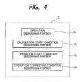
- FIG. 4 is an explanatory diagram illustrating a constitution of each command stored in a shared memory according to the first embodiment of the present invention
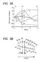
- FIG. 5A is an explanatory diagram of operation command data to be output to joints of a multi-joint robot main body, and a time chart in a case where pieces of operation command data to be output to the respective joints are arranged in time series.
- FIG. 5B is an explanatory diagram of the operation command data to be output to each of the joints of the multi-joint robot main body, and an enlarged diagram illustrating sequences of command values of a part surrounded with a circle of FIG. 5A .
- FIG. 6 is a time chart illustrating an operation example which uses three commands.
- FIG. 7 is an explanatory chart illustrating a flow of an operation of a robot controlling device according to a second embodiment of the present invention.
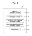
- FIG. 8 is an explanatory diagram illustrating a constitution of each command stored in a shared memory of the robot controlling device according to the second embodiment of the present invention.
- FIG. 9 is an explanatory chart illustrating a flow of an operation of a first processing unit of a robot controlling device according to a third embodiment of the present invention.
- FIG. 10 is an explanatory chart illustrating a flow of an operation of a second processing unit of the robot controlling device according to the third embodiment of the present invention.
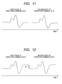
- FIG. 11 is a diagram illustrating an example of operation command data generated by a robot controlling device according to a fourth embodiment of the present invention.
- FIG. 12 is a diagram illustrating an example of operation command data generated by a robot controlling device according to a comparative example.
- FIG. 13 is an explanatory chart illustrating a flow of an operation of a robot controlling device according to a fifth embodiment of the present invention.
- FIG. 14 is a diagram illustrating an example of operation command data having an offset value added thereto and generated by the robot controlling device according to the fourth embodiment of the present invention.
- FIG. 1 is an explanatory view illustrating a schematic constitution of a robot apparatus according to a first embodiment of the present invention.
- a robot apparatus 50 includes a multi-joint robot main body 100, and a robot controlling device 200 which controls the multi-joint robot main body 100.
- the multi-joint robot main body 100 includes a plurality of links 101 to 105, and a hand 106 which is an end effector connected to the tip link 105, and the links 101 to 105 and the hand 106 are swingably or pivotably interconnected via joints J1 to J6.
- the multi-joint robot main body 100 is a six-axes multi-joint robot in which a degree of freedom is 6.
- FIG. 2 is a block diagram illustrating the schematic constitution of the robot apparatus 50.
- the joints J1 to J6 are provided with arm motors Ma (Ma 1 to Ma 6 ) as a plurality of driving units which drive the joints J1 to J6, and the hand 106 is provided with a motor Mb for the hand.
- the multi-joint robot main body 100 includes a direct acting actuator, a cylinder and the like.
- the arm motors Ma, the hand motor Mb, the direct acting actuator and the cylinder constitute an output device 214.
- the joints J1 to J6 are provided with arm encoders Ea which detect rotation angles of the arm motors Ma.
- the hand 106 is provided with a hand encoder Eb which detects a rotation angle of the hand motor Mb.
- a force sensor Sa which detects a force and a torque acting on the hand 106.
- the multi-joint robot main body 100 is provided with a current sensor which detects a current supplied to each of the motors Ma and Mb, and a torque sensor which detects the torque of each of the joints J1 to J6.
- These encoders Ea and Eb, the force sensor Sa, the current sensor and the torque sensor constitute an input device 215 as a sensor which detects a state of the multi-joint robot main body 100.
- the input device 215 and the output device 214 are generically referred to as devices 207.
- the robot controlling device 200 roughly includes a first processing unit 201, a second processing unit 202, and a shared memory 203.
- the first processing unit 201 and the second processing unit 202 are accessibly connected to the shared memory 203.
- the robot controlling device 200 includes one dual core CPU, and cores in the dual core CPU perform functions of the first processing unit 201 and the second processing unit 202, respectively.
- the robot controlling device 200 may include two single cores CPUs and the CPUs may perform the functions of the first processing unit 201 and the second processing unit 202, respectively.
- the first processing unit 201 inputs a command to operate the multi-joint robot main body 100 to a desired position posture, and calculates, on the basis of this input command, operation command data (track data) where command values of joint angles to be output to the motors Ma 1 to Ma 6 are arranged in time series. Then, the operation command data as the calculation results is stored in the shared memory 203. In consequence, the first processing unit 201 performs track calculation processing in which times required for the calculations based on inverse kinematics are indefinite.
- the second processing unit 202 performs synchronous processing which includes acquiring the operation command data stored in the shared memory 203, and synchronously outputting the command values to the motors Ma 1 to Ma 6 at predetermined time intervals. That is, the first embodiment allows the first processing unit 201 to perform the intricate track calculation processing in which the times required for the calculations are indefinite, and allows the second processing unit 202 to perform the synchronous processing of the motors Ma 1 to Ma 6 .
- the first processing unit 201 includes a calculation start condition determining unit 211 and a calculating unit 212.
- the second processing unit 202 includes an operation start condition determining unit 221, a receiving unit 222, a command value correcting unit 223, a transmitting unit 224 and an operation completing condition determining unit 225.
- FIG. 3 is an explanatory chart illustrating a flow of an operation of each unit of the robot controlling device 200.
- a command set A including a plurality of commands C 1 , C 2 , C 3 and the like is beforehand stored as shown in FIG. 3 . That is, in the shared memory 203, a plurality of commands for determining the joint angles of the multi-joint robot main body 100 are beforehand stored.
- the command set A is prepared in the form of, for example, a text type file for a purpose that a user describes an operation of a robot. A large number of commands are usually combined to realize the robot operation. As shown in FIG.
- each of commands C n includes an operation describing portion c 1 , a calculation start condition describing portion c 2 , an operation start condition describing portion c 3 , and an operation completing condition describing portion c 4 .
- a command for allowing each of the motors Ma 1 to Ma 6 to perform a driving operation will be described among the commands stored in the shared memory 203.
- the operation describing portion c 1 there is described a command to operate the multi-joint robot main body 100 (more specifically, the hand 106 of the multi-joint robot main body 100) to a desired position posture.
- the command has the same meaning as "a job” or "an instruction”.
- the command specifies the desired position posture of the hand 106 of the multi-joint robot main body 100 in an orthogonal coordinate system.
- the desired position posture of the hand 106 is specified by (X, Y, Z, ⁇ x , ⁇ y , ⁇ z ) in the orthogonal coordinate system.
- a command to specify a relative position posture of the hand 106 from the present position posture thereof is described in the operation describing portion c 1 .
- calculation start condition describing portion c 2 there are described conditions to start the track calculation by the calculating unit 212. For example, when another included command is executed, the command establishes a final desired position to be reached by the hand 106, and then the unit starts the calculation. Such conditions are described in the calculation start condition describing portion c 2 . Moreover, for example, when the operation of the multi-joint robot main body 100 stops, the unit starts the calculation. When a value of the sensor is established, the unit starts the calculation. Such conditions are described in the calculation start condition describing portion c 2 .
- operation start condition describing portion c 3 there are described conditions to start the operation of each of the motors Ma 1 to Ma 6 for executing the command. For example, when two arms cooperatively operate, it is necessary to simultaneously start the operations. Therefore, for example, operation start conditions to wait for the calculation of two tracks are described in the operation start condition describing portion C 3 .
- the operation completing condition describing portion c 4 there are described conditions to complete the operations of the motors Ma 1 to Ma 6 .
- the operations of the motors Ma 1 to Ma 6 are completed.
- Such conditions are described in the operation completing condition describing portion C 4 .
- commands for allowing the motor Mb, the direct acting actuator not shown, the cylinder not shown and the like to perform the driving operations have constitutions similar to those of the commands for the track calculation, and the commands are beforehand stored in the shared memory 203.
- the shared memory 203 there is also stored a command for allowing the input device (the sensor) 215 to perform a measurement operation.
- the command for allowing the input device 215 to perform the measurement operation will be described.
- a measurement request for the input device 215 is described.
- the calculation start condition describing portion c 2 there are described conditions to start measurement preparation required before the input device 215 performs the measurement. For example, when the input device 215 is the force sensor Sa or a visual sensor attached to the hand 106, there are described conditions that the device waits until the hand 106 reaches the desired position posture.
- operation start condition describing portion c 3 conditions for allowing the input device 215 to start the measurement operation are described.
- the input device 215 is the visual sensor
- the operation completing condition describing portion c 4 conditions to complete the measurement operation by the input device 215 are described. For example, conditions to determine whether or not a measured value becomes stable are described.
- the calculation start condition determining unit 211 successively refers to the calculation start condition describing portions c 2 of the plurality of commands C 1 , C 2 , C 3 and the like in the command set A stored in the shared memory 203. Then, the calculation start condition determining unit 211 acquires, from the shared memory 203, the command described in the operation describing portion c 1 of the command which satisfies the calculation start conditions.
- the calculation start condition determining unit 211 waits until the conditions are satisfied, if there is not any command that satisfies the calculation start conditions. Therefore, first at the start, it is necessary for at least one of the plurality of commands C 1 , C 2 , C 3 and the like to satisfy the calculation start conditions. Moreover, although not shown, the device can be started by changing the calculation start conditions of the command from the outside.
- the calculating unit 212 calculates, on the basis of the command, operation command data B where the command values of the joint angles to be output to the motors Ma 1 to Ma 6 are arranged in time series, based on an inverse kinematic model. Then, the calculating unit 212 stores the operation command data B as calculation results in the shared memory 203. Since pieces of operation command data B calculated by the calculating unit 212 are successively stored in the shared memory 203, the pieces of operation command data B are stored.
- FIG. 5A is a time chart in a case where the pieces of operation command data B to be output to the respective joints are arranged in time series.
- the calculation start condition determining unit 211 acquires a command to move the multi-joint robot main body 100 from a position posture P1 to a position posture P3 via a position posture P2 shown in FIG. 5A
- the calculating unit 212 calculates the operation command data B on the basis of the command.
- command values indicating the joint angles of the joints J1 to J6, to be output to the motors Ma 1 to Ma 6 are arranged in time series.
- FIG. 5B is an enlarged diagram illustrating sequences of command values of a part surrounded with a circle of FIG. 5A .
- command values d1 1 to d1 9 are calculated for the motor Ma 1 in the joint J1
- command values d6 1 to d6 9 are calculated for the motor Ma 6 in the joint J6.
- the second processing unit 202 outputs the respective command values to the motors Ma 1 to Ma 6 at predetermined time intervals ⁇ t (i.e. every synchronous time ⁇ t).
- the first processing unit 201 performs the track calculation processing in which the calculations are intricate and times required for the calculations are indefinite.
- the calculation start condition determining unit 211 performs the operation again.
- the calculating unit 212 does not perform the track calculation of the hand motor Mb, the direct acting actuator, the cylinder and the like, but calculates the operation command data thereof, including the command values, based on the input command. This also applies to the input device 215.
- the calculating unit does not calculate any track as in the motors Ma 1 to Ma 6 , but performs the calculation before the measurement. For example, in the case of the force sensor Sa, the calculating unit calculates the value thereof, when the multi-joint robot main body 100 (the hand 106) comes to a predetermined position, whereby measurement command data as the calculation results is stored in the shared memory 203.
- the operation start condition determining unit 221 refers to the operation start condition describing portions c 3 of the commands C 1 , C 2 , C 3 and the like stored in the shared memory 203. Then, the operation start condition determining unit 221 acquires, from the shared memory 203, the operation command data B corresponding to the command satisfying operation start conditions among the pieces of operation command data B and the like stored in the shared memory 203. At this time, in a case where a plurality of commands satisfy the operation start conditions, the operation start condition determining unit 221 acquires the pieces of operation command data from the shared memory 203. It is to be noted that also as to the measurement command data, when the command satisfies the operation start conditions, the operation start condition determining unit 221 acquires, from the shared memory 203, the measurement command data corresponding to the command.
- the receiving unit 222 inputs signals as detection results from the input device 215 (the sensor). Then, in a case where the operation start condition determining unit 221 acquires the measurement command data, the detection results are corrected. For example, in the case of the force sensor Sa, a command value of the measurement command data is subtracted from the detection result every time the measurement is actually performed, whereby an influence of a gravity force is alleviated. For example, in the case of the visual sensor, a three-dimensional position to which the visual sensor is attached is calculated from the joint angles of the multi-joint robot main body 100, and used for the correction during the actual measurement.
- the command value correcting unit 223 corrects the respective command values of the operation command data B acquired by the operation start condition determining unit 221, which are to be synchronously output to the motors Ma 1 to Ma 6 , by use of the signal from the input device 215, whereby the unit outputs the command values to the transmitting unit 224.
- the input device 215 is, for example, the force sensor Sa
- force feedback control can be executed.
- the input device 215 is the visual sensor
- visual feedback control can be executed.
- a method of calculating a correcting amount is already known.
- impedance control or force control such as compliance control described in a document ( Robot Engineering Handbook edited by the Robotics Society of Japan and published by Corona Publishing Co., Ltd. (Tokyo), 2005, 287 pages ) can be utilized.
- the transmitting unit 224 inputs the respective corrected command values acquired from the shared memory 203, and synchronously outputs the respective command values to the motors Ma 1 to Ma 6 at predetermined time intervals ⁇ t, i.e., every synchronous time ⁇ t.
- This synchronous time ⁇ t is as short as milliseconds, for example, five milliseconds.
- the operation completing condition determining unit 225 determines whether or not the operation is completed, based on operation completing conditions in the processed command. Then, an operation result D is stored in the shared memory 203.
- the above-mentioned operations of the units 221 to 225 are repeatedly performed every synchronous time ⁇ t.
- FIG. 6 illustrates a time chart of an operation example which uses three commands.
- the calculating unit 212 of the first processing unit 201 calculates the operation command data corresponding to the command C 1 based on the command C 1 acquired from the shared memory 203, to store the data in the shared memory 203.
- the calculating unit 212 calculates the operation command data corresponding to the command C 2 based on the command C 2 acquired from the shared memory 203, to store the data in the shared memory 203.
- the calculating unit 212 calculates the operation command data corresponding to the command C 3 based on the command C 3 acquired from the shared memory 203, to store the data in the shared memory 203. In this manner, the calculating unit 212 of the first processing unit 201 successively calculates the respective commands one by one to store the calculation results in the shared memory 203.
- the second processing unit 202 can operate independently of the calculating operation of the first processing unit 201, for example, even while the calculating unit 212 of the first processing unit 201 calculates the operation command data on the basis of the command C 3 . Therefore, the operation start condition determining unit 221 of the second processing unit 202 accesses the shared memory 203 without waiting for the end of the calculation based on the command C 3 by the first processing unit 201, and acquires the operation command data of the commands C 1 and C 2 . Then, the second processing unit executes the respective operations of the commands C 1 and C 2 . Afterward, the second processing unit 202 executes the operation of the command C 3 .
- the track calculation processing and synchronous processing can be performed in parallel, which shortens the operation time of the robot apparatus 50.
- the shortening of the operation time is very important in that product cost can be reduced, in a case where the robot apparatus 50 is incorporated in a production apparatus.
- the first embodiment allows the first processing unit 201 to perform the track calculation processing, to store the operation command data B as the calculation results in the shared memory 203, so that the second processing unit 202 does not have to perform any intricate track calculation processing. Therefore, even when the first processing unit 201 takes long calculation time, the second processing unit 202 does not perform any track calculation processing based on the inverse kinematics. Therefore, immediately after the operation start conditions are satisfied, the respective motors Ma 1 to Ma 6 can be operated.
- the second processing unit 202 does not perform any intricate track calculation processing, but performs the synchronous processing which includes synchronously outputting, to the motors Ma 1 to Ma 6 , the command values of the operation command data B already calculated by the first processing unit 201. Therefore, the processing can be realized without stopping the operation of the multi-joint robot main body 100, and the multi-joint robot main body 100 can smoothly be operated, which enables the multi-joint robot main body 100 to perform a humanly dextrous operation.
- the robot apparatus can be synchronized with another operation apparatus (e.g. a movable table on which a grasping object is mounted).
- another operation apparatus e.g. a movable table on which a grasping object is mounted.
- the one robot controlling device 200 controls the one multi-joint robot main body 100.
- the same control operation is performed also in a case where the one robot controlling device 200 controls a plurality of multi-joint robot main bodies. That is, in the shared memory 203, commands for the respective multi-joint robot main bodies are beforehand stored, and the respective processing units 201 and 202 perform the track calculation processing and synchronous processing based on the commands, respectively.
- the commands C 1 and C 2 can simultaneously be output as shown in, for example, FIG. 6 . Therefore, the plurality of multi-joint robot main bodies can synchronously be operated without being stopped. In consequence, the plurality of multi-joint robot main bodies can smoothly be operated, which enables the plurality of multi-joint robot main bodies to perform the humanly dextrous operation.
- FIG. 7 is an explanatory chart illustrating a flow of an operation of a robot controlling device 200A
- FIG. 8 is an explanatory diagram illustrating a constitution of each command stored in a shared memory. It is to be noted that in the second embodiment, constitutions similar to the above first embodiment are denoted with the same reference marks, and the descriptions thereof are omitted.
- each of commands C n beforehand stored in a shared memory 203 further includes a state variable c 5 in addition to an operation describing portion c 1 , a calculation start condition describing portion c 2 , an operation start condition describing portion c 3 , and an operation completing condition describing portion c 4 described above in the first embodiment.
- the state variable c 5 is a value which means one of a calculation start waiting state, a calculating state, a calculation completing state, an operating state, and an operation completing state. First at the start, the state variable c 5 is set to the calculation start waiting state.
- the calculation start waiting state is a state where the start of calculation of tracks is waited.
- the calculating state is a state where a calculating unit 212 shown in FIG. 7 starts the track calculation, and is calculating the tracks.
- the calculation completing state is a state where the calculation by the calculating unit 212 is completed, and operation command data B is stored in the shared memory 203.
- the operating state is a state where a second processing unit 202A starts an operation, and is operating, and the operation completing state is a state where the second processing unit 202A completes the operation.
- a first processing unit 201A shown in FIG. 7 includes a first state variable changing unit 301 and a second state variable changing unit 302 in addition to a calculation start condition determining unit 211A and the calculating unit 212.
- the calculation start condition determining unit 211A refers to a calculation start condition describing portion c 2 of each of commands C 1 , C 2 , C 3 and the like stored in the shared memory 203. Then, the calculation start condition determining unit 211A extracts a command which satisfies calculation start conditions and in which a state variable c 5 has a calculation start waiting state. Then, the calculation start condition determining unit 211A acquires, from the shared memory 203, one command described in an operation describing portion c 1 included in the command.
- the calculation start condition determining unit 211A waits until the calculation conditions are satisfied. Therefore, first at the start, at least one command has to satisfy the calculation start conditions. Moreover, even when all the commands do not satisfy the calculation start conditions, it is easy to change the calculation start conditions and start from an external program not shown. For example, the state variable may be changed to the start waiting state.
- the first state variable changing unit 301 changes, from the calculation start waiting state to the calculating state, the state variable c 5 of the command acquired from the commands C 1 , C 2 , C 3 and the like stored in the shared memory 203 by the calculation start condition determining unit 211A.
- the calculating unit 212 calculates the operation command data B on the basis of the command acquired by the calculation start condition determining unit 211A, and stores the operation command data B in the shared memory 203.
- the calculation start condition determining unit 211A does not acquire any command from the commands in which the state variables c 5 have states other than the calculation start waiting state, which can avoid redundant calculation.
- the second state variable changing unit 302 changes the state variable c 5 of the command corresponding to the operation command data completed to be calculated by the calculating unit 212 among the commands C 1 , C 2 , C 3 and the like stored in the shared memory 203, in a case where the calculating unit 212 completes the calculation. Specifically, the unit changes the state variable c 5 from the calculating state to the calculation completing state.
- the operation by the calculation start condition determining unit 211A is performed again.
- the second processing unit 202A includes a third state variable changing unit 303 and a fourth state variable changing unit 304 in addition to an operation start condition determining unit 221A, a receiving unit 222, a command value correcting unit 223, a transmitting unit 224 and an operation completing condition determining unit 225.
- the operation start condition determining unit 221A refers to an operation start condition describing portion c 3 of each of the commands C 1 , C 2 , C 3 and the like stored in the shared memory 203. Then, the operation start condition determining unit 221A acquires, from the shared memory 203, the operation command data B corresponding to a command which satisfies operation start conditions and in which the state variable c 5 has a calculation completing state among pieces of operation command data B and the like stored in the shared memory 203. At this time, when a plurality of commands satisfy the operation start conditions and have the calculation completing state, the operation start condition determining unit 221A acquires all the pieces of operation command data B satisfying the conditions from the shared memory 203.
- the third state variable changing unit 303 changes, from the calculation completing state to the operating state, the state variable c 5 of the command corresponding to the operation command data B acquired from the commands stored in the shared memory 203 by the operation start condition determining unit 221A. In consequence, the redundant execution of the operating command can be avoided, and control becomes stable.
- the receiving unit 222 inputs a signal as a detection result from an input device 215 (a sensor). Then, the detection result is corrected in a case where the operation start condition determining unit 221A acquires measurement command data. For example, in the case of a force sensor Sa, a command value of the measurement command data is subtracted from the detection result every time the measurement is actually performed, whereby an influence of a gravity force is alleviated. Moreover, for example, in the case of a visual sensor, a three-dimensional position to which the visual sensor is attached is calculated from joint angles of a multi-joint robot main body 100, and used for the correction during the actual measurement.
- the command value correcting unit 223 corrects the respective command values of the operation command data B acquired by the operation start condition determining unit 221A, which are to be synchronously output to the motors Ma 1 to Ma 6 , by use of the signal from the input device 215, whereby the unit outputs the command values to the transmitting unit 224.
- the input device 215 is, for example, the force sensor Sa
- force feedback control can be executed.
- the input device 215 is the visual sensor
- visual feedback control can be executed.
- the transmitting unit 224 inputs the respective corrected command values acquired from the shared memory 203, and synchronously outputs the respective command values to the motors Ma 1 to Ma 6 at predetermined time intervals ⁇ t, i.e., every synchronous time ⁇ t.
- This synchronous time ⁇ t is as short as milliseconds, for example, five milliseconds.
- the operation completing condition determining unit 225 determines whether or not the operation is completed, based on operation completing conditions in the processed command. Then, an operation result D is stored in the shared memory 203.
- the fourth state variable changing unit 304 changes, from the operating state to the operation completing state, the state variable c 5 of the command corresponding to the operation command data B when the operation is completed, among the commands stored in the shared memory 203.
- the above-mentioned operations of the respective units 221A to 304 are repeatedly performed every synchronous time ⁇ t. It is to be noted that the units similarly operate, also in a case where the command stored in the shared memory 203 is a command for the input device 215.
- the second embodiment allows the first processing unit 201A to perform the track calculation processing, to store the operation command data B as the calculation results in the shared memory 203, and hence the second processing unit 202A does not have to perform any intricate track calculation processing. Therefore, even if the first processing unit 201A takes long calculation time, the second processing unit 202A does not perform any track calculation processing based on inverse kinematics. Therefore, immediately after the operation start conditions are satisfied, the motors Ma 1 to Ma 6 can be operated.
- the second processing unit 202A does not perform any intricate track calculation processing, but performs synchronous processing which includes synchronously outputting, to the motors Ma 1 to Ma 6 , the command values of the operation command data B already calculated by the first processing unit 201A. Therefore, the processing can be realized without stopping the operation of the multi-joint robot main body 100, and the multi-joint robot main body 100 can smoothly be operated, which enables the multi-joint robot main body 100 to perform a humanly dextrous operation.
- the calculating unit 212 can start the calculation at an appropriate timing.
- the second processing unit 202A includes the operation start condition determining unit 221A, it is possible to start the operation at the appropriate timing. That is, since the respective track calculation processing and synchronous processing can be performed at a satisfactory timing in accordance with the commands C 1 , C 2 , C 3 and the like, a robot apparatus can be synchronized with another operation apparatus (e.g. a movable table on which a grasping object is mounted).
- another operation apparatus e.g. a movable table on which a grasping object is mounted.
- the commands C 1 , C 2 , C 3 and the like include the state variables c 5 . Therefore, when the state variables c 5 are monitored, control operations by the first processing unit 201A and the second processing unit 202A becomes stable.
- the one robot controlling device 200A controls the one multi-joint robot main body 100.
- the same control operation is performed in a case where the one robot controlling device 200A controls a plurality of multi-joint robot main bodies. That is, in the shared memory 203, commands for the respective multi-joint robot main bodies are beforehand stored, and the processing units 201A and 202A perform the track calculation processing and synchronous processing based on the commands, respectively.
- the commands C 1 and C 2 can simultaneously be output as shown in, for example, FIG. 6 . Therefore, the plurality of multi-joint robot main bodies can synchronously be operated without being stopped. In consequence, the plurality of multi-joint robot main bodies can smoothly be operated, which enables the plurality of multi-joint robot main bodies to perform the humanly dextrous operation.
- FIG. 9 is an explanatory chart illustrating a flow of an operation of each unit in a first processing unit of the robot controlling device.
- FIG. 10 is an explanatory chart illustrating a flow of an operation of each unit in a second processing unit of the robot controlling device.
- the robot controlling device includes a first processing unit 201B shown in FIG. 9 and a second processing unit 202B shown in FIG. 10 .
- a calculation start condition determining unit 211A refers to a calculation start condition describing portion c 2 of each of commands C 1 , C 2 , C 3 and the like in a command set A stored in a shared memory 203, and selects a command which satisfies calculation start conditions (401).
- the calculation start condition determining unit 211A searches for the command on conditions that a state variable c 5 is a calculation start waiting state (402).
- the unit again refers to the calculation start condition describing portion c 2 of each of the commands C 1 , C 2 , C 3 and the like in the command set A stored in the shared memory 203, and selects the command which satisfies the calculation start conditions.
- a first state variable changing unit 301 changes the state variable c 5 from the calculation start waiting state to a calculating state.
- a calculating unit 212B calculates operation command data B based on the command acquired by the calculation start condition determining unit 211A.
- the calculating unit 212B includes a processing selection unit 403, a motor control calculating unit 404, a sensor control calculating unit 405, an external apparatus control unit 406, a correcting unit 407, and an operation command data output unit 408.
- the processing selection unit 403 interprets contents of the command.
- the motor control calculating unit 404 calculates tracks of joints of the multi-joint robot main bodies 100a and 100b with respect to arm motors Ma 1 to Ma 6 . After the tracks are determined, the unit calculates a speed of each joint advancing along the track so that during accelerating and decelerating, a maximum acceleration, a maximum speed and a maximum motor torque are not exceeded.
- Various calculation methods have been suggested. For example, the following document discusses the method of calculating the tracks. J. E. Bobrow, S. Dubowsky, J. S. Gibson: Time-Optimal Control of Robotic Manipulators Along Specified Paths, the International Journal of Robotics Research, Vol. 4, No. 3 (1985), p. 3-17 .
- Such calculation of the tracks requires a first mechanical model 409 which is the model of inverse kinematics.
- the first mechanical model 409 is a simulator of the multi-joint robot main bodies 100a and 100b, and includes an inverse calculating unit.
- the motor control calculating unit 404 calculates the torque and acceleration applied to the respective joints when the multi-joint robot main bodies 100a and 100b are operated, to perform the track calculation, thereby calculating the operation command data B.
- the sensor control calculating unit 405 calculates measurement command data to output the data to an input device (a sensor) 215.
- the external apparatus control unit 406 copes with commands of external apparatuses other than the motors of the multi-joint robot main bodies 100a and 100b, for example, tables controlled by the motors and air cylinders.
- the unit outputs the operation command data to devices, respectively.
- the correcting unit 407 corrects the calculated operation command data B.
- a multi-joint robot has a positioning accuracy which is lower than a position reproducibility. For example, if a hand of a six-axes multi-joint robot main body is linearly moved, the hand undulates owing to a length between the joints and a joint attaching error. A movement error due to such causes is reproduced. Therefore, when the hand moves next time, improvement based on the result of the previous movement can be expected. Therefore, the third embodiment adds learning data 410 beforehand stored in the shared memory 203. A method of obtaining the learning data 410 can be performed by a known technology.
- the next operation command is corrected based on a difference between an once moved track and a desired track. In consequence, the track can be brought close to the desired track.
- the operation command data output unit 408 outputs, to the shared memory 203, the corrected operation command data B calculated by using the first mechanical model 409.
- the operation command data B is stored in a memory area which is separate from a memory area where the command set A is stored.
- the operation command data B is generated every time the command is processed. Therefore, pieces of the operation command data B are stored in the shared memory 203.
- the first processing unit 201B restarts the processing of another command in the calculation start condition determining unit 211A.
- the second processing unit 202B includes an operation start condition determining unit 221A, a receiving unit 222, a command value correcting unit 223, a transmitting unit 224, an operation completing condition determining unit 225, a third state variable changing unit 303 and a fourth state variable changing unit 304 in the same manner as in the above second embodiment. Furthermore, the second processing unit 202B includes a buffer writing unit 413, an all data writing determining unit 414, a buffer unit 415, a buffer reading unit 416 and a robot state monitoring unit 417.
- the operation start condition determining unit 221A refers to an operation start condition describing portion c 3 of each of the commands C 1 , C 2 , C 3 and the like corresponding to the respective pieces of operation command data in pieces of operation command data B 1 , B 2 , B 3 and the like, and selects all the pieces of operation command data that satisfy operation start conditions (411). At this time, the operation start condition determining unit 221A searches for the data on conditions that the state variable c 5 is a calculation completing state (412). In consequence, the operation start condition determining unit 221A acquires all the pieces of operation command data that satisfy the operation start conditions.
- the flow advances to the buffer reading unit 416.
- the buffer writing unit 413 writes the data in the buffer unit 415.
- the buffer unit 415 is called a ring buffer, and includes tracks corresponding to devices 207, respectively. That is, the buffer unit 415 includes (six) tracks corresponding to the arm motors Ma 1 to Ma 6 , respectively, and additionally includes tracks corresponding to the other devices, respectively.
- the buffer unit 415 holds a writing position and a reading position.
- the buffer unit 415 is a matrix-like memory area, and the number of rows (the tracks) corresponds to the number of all the devices 207, and is called a track width. For example, when 30 motors and sensors are provided in all, the buffer unit has a track width of 30 rows.
- a column direction indicates time, and one column indicates one zone of synchronous time ⁇ t. For example, when the synchronous time interval ⁇ t is 1 ms and 40 seconds are accumulated, the number of the columns is 40,000.
- the buffer writing unit 413 uses the writing position of the buffer unit 415 as a reference, to continuously write the command values of the operation command data acquired by the operation start condition determining unit 221A in the track corresponding to each of the devices 207 in order of time series.
- the buffer reading unit 416 reads the command values to be output at the same time from the respective tracks of the buffer unit 415.
- the unit is characterized by reading the command values of the operation command data for all the devices 207 at the same time. Moreover, after the reading, the next reading column is shifted as much as one column. If the unit reaches the last column, the unit returns to the first column. That is, the buffer unit 415 has a ribbon-like ring shape with the track width. Moreover, the buffer unit 415 first resets the whole unit to a state of "no operation command".
- the buffer writing unit 413 writes the operation command data acquired by the operation start condition determining unit 221A from the writing position of the buffer unit 415 into the corresponding track.
- the writing position is advanced as much as the written pieces of data.
- the writing position reaches the terminal end of the buffer unit 415, the position is returned to the top of the buffer unit 415.
- the remaining command values are written in the buffer unit 415 at the next turn.
- the writing position advances as much as the written data pieces (the command values), and hence continuity is not lost.
- the all data writing determining unit 414 determines whether or not all the writing of the operation command data is completed. If the processing is not completed, the processing advances to processing of the buffer reading unit 416. Here, in the case where the processing is not completed, only part of the command values is written as described above, and the command values are left in the operation command data.
- the third state variable changing unit 303 changes the state variable c 5 from the calculation completing state to an operating state.
- the buffer reading unit 416 reads the operation command data from the reading position of the buffer unit 415. By the reading from the buffer unit 415, the data (the command values) for all the devices 207 can simultaneously be acquired. After reading the data, the buffer reading unit 416 performs the following two operations. In the first operation, the data at the reading position is cleared, and the state is returned to the original state without any operation command. In the second operation, the reading position is updated to the next position. At this time, in a case where the reading position reaches the terminal end of the buffer unit 415, the position is returned to the top of the buffer unit 415. Therefore, when the buffer writing unit 413 does not write any operation command, the state without any operation command is read.
- the operation command data B stored in the shared memory 203 is once stored in the buffer unit 415, which can noticeably decrease the number of times to access the shared memory 203. This eventually decreases the number of access colliding times when both the first processing unit 201B and the second processing unit 202B simultaneously access the shared memory 203, whereby an operation speed increases.
- the receiving unit 222 inputs a measured value from the input device 215 (the sensor).
- the input device is, for example, an encoder
- the receiving unit receives a rotation angle position of a motor.
- each of receivers 222b inputs a signal from each of the input devices 215, and outputs each measured value to a receiving control unit 222a.
- the receiving control unit 222a corrects each measured value, and outputs the value to the command value correcting unit 223.
- the command value correcting unit 223 corrects the operation command data B based on the input measured value.
- the input device 215 is a force sensor
- force feedback control can be executed
- visual feedback control can be executed.
- the transmitting unit 224 transmits the command values of the operation command data B to the devices 207.
- the transmitting unit transmits the command value indicating a motor joint angle
- the unit transmits the command value indicating a signal input command.
- a transmitting control unit 224a outputs each command value at predetermined time, and each of transmitters 224b outputs the value to each output device 214.
- the respective output devices 214 operate based on the input command values.
- the robot state monitoring unit 417 monitors postures of the multi-joint robot main bodies 100a and 100b, and calculates position postures of the multi-joint robot main bodies 100a and 100b (the hands) by use of a second mechanical model 418 which is a forward kinematic model. For example, the calculation results of the hand position posture are used for determination in a case where the hand entering a preset movement prohibition region is stopped.
- the first processing unit 201B calculates command values indicating joint angles of the multi-joint robot main bodies 100a and 100b from the position postures of the hands of the multi-joint robot main bodies 100a and 100b, by use of the first mechanical model 409.
- the second processing unit 202B uses the second mechanical model 418 which is separate from the first mechanical model 409, when monitoring the states of the multi-joint robot main bodies 100a and 100b. That is, the robot state monitoring unit 417 executes forward calculation by use of the second mechanical model 418 to calculate the positions of the hands of the multi-joint robot main bodies 100a and 100b from the joint angles of the multi-joint robot main bodies 100a and 100b. Then, the robot state monitoring unit 417 stores the calculation results in a memory area which is separate from the memory areas of the command set A and operation command data B in the shared memory 203.
- the first processing unit 201B and the second processing unit 202B are provided with two respective independent mechanical models 409 and 418, the units do not interfere with each other. That is, the second processing unit 202B updates the contents of the memory which holds the position postures of the multi-joint robot main bodies 100a and 100b (the hands). However, the data is stored in the memory area which is separate from the memory areas of the command set A and operation command data B, and hence the units do not influence each other.
- the operation completing condition determining unit 225 determines whether or not the operation is completed, based on operation completing conditions in the processed command. In a method of determining the completion of the operation, it is determined that the operation is completed, for example, when all the command values of the operation command data are read from the buffer unit 415 and transmitted to the device 207. Alternatively, when the positions of the hands of the multi-joint robot main bodies 100a and 100b enter a preset movement completion region, it is determined that the operation is completed. In the case of the completion of the operation, the fourth state variable changing unit 304 changes the state variable c 5 from the operating state to an operation completing state. The above processing of the second processing unit 202B is repeatedly performed every predetermined synchronous time ⁇ t.
- the third embodiment allows the first processing unit 201B to perform the track calculation processing, to store the operation command data B as the calculation results in the shared memory 203, and hence the second processing unit 202B does not have to perform any intricate track calculation processing.
- the synchronous processing which includes synchronously outputting the command values of the operation command data B already calculated by the first processing unit 201B to the motors Ma 1 to Ma 6 , without stopping the operations of the multi-joint robot main bodies 100a and 100b. This enables the multi-joint robot main bodies 100a and 100b to perform a humanly dextrous operation.
- FIG. 11 is a diagram illustrating an example of operation command data generated by the robot controlling device.
- a multi-joint robot main body is multi-axial, and hence a plurality of command value sequences are output to the motors of joints, but only one command value sequence is illustrated for description.
- a first piece of operation command data is the same as a second piece of operation command data, and hence the calculation of the second and subsequent pieces of operation command data can be omitted.
- a calculating unit 212 determines whether or not the operation command data calculated on the basis of a command acquired by a calculation start condition determining unit 211 (211A) matches operation command data B stored in a shared memory 203. Then, in a case where the calculating unit 212 (212B) determines that these pieces of data match each other, the calculation of the operation command data is omitted.
- the operation command data stored in the shared memory 203 is not deleted but is left, even if the data is once read by an operation start condition determining unit 221 (221A).
- the operation start condition determining unit 221 (221A) can acquire the operation command data again, because the operation command data is not deleted but is left in the shared memory 203.
- commands C 1 , C 2 , C 3 and the like have flags each indicating whether or not the operation command data has been calculated, and the calculating unit 212 (212B) can determine whether or not the data has been calculated, with reference to the flag. This flag is changed by the calculating unit 212 (212B), after the calculation by the calculating unit 212 (212B) ends.
- the operation command data calculated by a first operation is reused in second and subsequent operations. In this way, the intricate track calculations are omitted. Therefore, a multi-joint robot main body 100 can be operated at a higher speed, and a calculation ability of a first processing unit 201 (201A and 201B) can be set apart for later use.
- a robot controlling device according to a fifth embodiment of the present invention will be described.
- a terminal end value of one of two continuous pieces of operation command data matches a start end value of the other piece of operation command data as shown in FIG. 11 .
- a terminal end value of one of two continuous pieces of operation command data does not match a start end value of the other piece of operation command data, and the values shift from each other as much as a difference ⁇ f sometimes.
- the fifth embodiment performs processing which includes adding an offset value.
- FIG. 13 is a chart illustrating a flow of an operation of each unit of a robot controlling device 200C according to the fifth embodiment. It is to be noted that the device of FIG. 13 is different from the robot controlling device 200A of the above second embodiment in an operation of an operation start condition determining unit. The other constitutions are the same, and are, accordingly, denoted with the same reference numerals, and the descriptions thereof are omitted.
- a second processing unit 202C of the robot controlling device 200C includes an operation start condition determining unit 221C which is different from the above second embodiment.
- the operation start condition determining unit 221C has a function of operating in the same manner as in the operation start condition determining unit 221A of the second embodiment, and additionally includes an offset adding unit 501.
- the offset adding unit 501 of the operation start condition determining unit 221C calculates the difference ⁇ f between a last command value (a terminal end value) of operation command data previously acquired from a shared memory 203 and a first command value (a start end value) of operation command data presently acquired from the shared memory 203. Then, the offset adding unit 501 of the operation start condition determining unit 221C adds an offset value which gradually decreases from the difference ⁇ f as an initial value to zero, to the command value in order of time series from the first command value of the operation command data presently acquired from the shared memory 203.
- the offset adding unit 501 calculates a difference between top data of the operation command data and the present position, and adds, to the operation command data, the offset value which gradually decreases from the difference as the initial value to zero.
- FIG. 14 illustrates an example of the operation command data to which the offset value has been added.
- the offset function f(t) has two necessary requirements as follows.
- the requirements are that the initial value is equal to the difference ⁇ f, and the value decreases to zero with an elapse of time.
- the difference is ⁇ f
- time required until the offset value becomes zero is T and time elapsed from when the first command value of the operation command data to be reused is output is t
- the following offset function f(t) is effective.
- a driving unit examples include a servo motor and a linear motor, and additionally include a piezo-actuator and a cylinder which uses an air pressure.
- sensors including an encoder and a displacement gauge for measuring a rotation angle of a motor, a camera and a force detecting load cell. In the control of a multi-joint robot main body, it is necessary to execute intricate track calculations and synchronous operations in parallel, even if the track calculations are intricate and times required for the calculations are indefinite.
- a robot controlling device of the present invention includes a shared memory, and first and second processing units connected to the shared memory.
- the first processing unit performs track calculation processing which includes calculating operation command data indicating a series of command values to be output to arm motors, based on a command to operate the multi-joint robot main body to a desired position posture, and storing the calculated operation command data in the shared memory.
- the second processing unit performs synchronous processing which includes acquiring the operation command data stored in the shared memory, and synchronously outputting the command values to the arm motors at predetermined time intervals.
Landscapes
- Engineering & Computer Science (AREA)
- Robotics (AREA)
- Mechanical Engineering (AREA)
- Automation & Control Theory (AREA)
- Physics & Mathematics (AREA)
- Artificial Intelligence (AREA)
- Evolutionary Computation (AREA)
- Fuzzy Systems (AREA)
- Mathematical Physics (AREA)
- Software Systems (AREA)
- Numerical Control (AREA)
- Manipulator (AREA)
Applications Claiming Priority (1)
| Application Number | Priority Date | Filing Date | Title |
|---|---|---|---|
| JP2010248187A JP5743495B2 (ja) | 2010-11-05 | 2010-11-05 | ロボット制御装置 |
Publications (3)
| Publication Number | Publication Date |
|---|---|
| EP2450157A2 true EP2450157A2 (de) | 2012-05-09 |
| EP2450157A3 EP2450157A3 (de) | 2018-02-28 |
| EP2450157B1 EP2450157B1 (de) | 2019-03-27 |
Family
ID=45065642
Family Applications (1)
| Application Number | Title | Priority Date | Filing Date |
|---|---|---|---|
| EP11186062.3A Active EP2450157B1 (de) | 2010-11-05 | 2011-10-21 | Robotersteuervorrichtung |
Country Status (4)
| Country | Link |
|---|---|
| US (1) | US8744625B2 (de) |
| EP (1) | EP2450157B1 (de) |
| JP (1) | JP5743495B2 (de) |
| CN (1) | CN102528809B (de) |
Cited By (5)
| Publication number | Priority date | Publication date | Assignee | Title |
|---|---|---|---|---|
| EP2946253A4 (de) * | 2013-01-17 | 2016-10-12 | Abb Technology Ltd | Bewegungssteuerung und robotersteuerungssystem damit |
| CN107153404A (zh) * | 2016-03-04 | 2017-09-12 | 发那科株式会社 | 能够增加程序指令的解析位数的数值控制装置 |
| EP3291037A3 (de) * | 2016-09-02 | 2018-03-21 | Omron Corporation | Steuerungsvorrichtung und steuerungssystem |
| EP3812853A4 (de) * | 2018-06-22 | 2022-01-05 | Soft Servo Systems, Inc. | Bewegungssteuerungsprogramm, bewegungssteuerungsverfahren und bewegungssteuerungsvorrichtung |
| EP3812855A4 (de) * | 2018-06-22 | 2022-01-05 | Soft Servo Systems, Inc. | Bewegungssteuerungsprogramm, bewegungssteuerungsverfahren und bewegungssteuerungsvorrichtung |
Families Citing this family (25)
| Publication number | Priority date | Publication date | Assignee | Title |
|---|---|---|---|---|
| JP5743495B2 (ja) * | 2010-11-05 | 2015-07-01 | キヤノン株式会社 | ロボット制御装置 |
| JP5896789B2 (ja) | 2012-03-07 | 2016-03-30 | キヤノン株式会社 | ロボット制御装置、ロボット装置、ロボット制御方法、プログラム及び記録媒体 |
| WO2014110749A1 (en) * | 2013-01-17 | 2014-07-24 | Abb Technology Ltd. | Robot control system and method thereof |
| JP6211802B2 (ja) * | 2013-05-29 | 2017-10-11 | 日本電産サンキョー株式会社 | データ処理装置およびデータ処理方法 |
| JP6238628B2 (ja) | 2013-08-06 | 2017-11-29 | キヤノン株式会社 | ロボット装置、ロボット制御方法、ロボット制御プログラム及びロボット装置を用いた部品の製造方法 |
| JP6288104B2 (ja) * | 2013-11-05 | 2018-03-07 | 株式会社安川電機 | トレースデータ収集システム、操作端末、及びトレースデータ収集方法 |
| JP6510761B2 (ja) * | 2014-04-08 | 2019-05-08 | 川崎重工業株式会社 | データ採取システムおよび方法 |
| CN105500361B (zh) * | 2014-09-23 | 2017-07-11 | 上海通用汽车有限公司 | 一种连杆结构机械手的运动控制方法及系统 |
| CN104440910B (zh) * | 2014-11-07 | 2016-05-04 | 绵阳市维博电子有限责任公司 | 一种实现机器人双手臂同步控制的方法及系统 |
| CN105843081A (zh) * | 2015-01-12 | 2016-08-10 | 芋头科技(杭州)有限公司 | 控制系统及控制方法 |
| JP6700669B2 (ja) | 2015-04-07 | 2020-05-27 | キヤノン株式会社 | 制御方法、ロボット装置、プログラム、記録媒体、及び物品の製造方法 |
| KR102430277B1 (ko) | 2015-11-27 | 2022-08-09 | 큐렉소 주식회사 | 정형외과 수술용 마커 위치 확인 시스템 및 그 확인 방법 |
| DE102015225183B4 (de) * | 2015-12-15 | 2022-09-15 | Carl Zeiss Meditec Ag | Medizinische Vorrichtung mit einem medizinisch-optischen Gerät und einer Haltevorrichtung und Verfahren zum Betrieb der medizinischen Vorrichtung |
| JP6851837B2 (ja) * | 2017-01-20 | 2021-03-31 | キヤノン株式会社 | 制御装置、ロボットシステム、制御方法、プログラム、記録媒体及び物品の製造方法 |
| WO2018158601A1 (en) * | 2017-03-01 | 2018-09-07 | Omron Corporation | Monitoring devices, monitored control systems and methods for programming such devices and systems |
| CN107745382A (zh) * | 2017-09-29 | 2018-03-02 | 李少锋 | 机器手臂的同步控制系统 |
| CN109960178B (zh) * | 2017-12-26 | 2020-10-16 | 深圳市优必选科技有限公司 | 机器人及其关节运动控制方法、装置 |
| US11045950B2 (en) | 2018-11-02 | 2021-06-29 | Canon Kabushiki Kaisha | Driving device and detecting device |
| WO2020161880A1 (ja) * | 2019-02-08 | 2020-08-13 | 日本電気株式会社 | 動作モデル算出装置、制御装置、関節機構、動作モデル算出方法、プログラムが記録された記録媒体 |
| EP3956112B1 (de) * | 2019-04-17 | 2024-03-06 | Universal Robots A/S | Verfahren zur steuerung eines roboterarms auf der basis adaptiver reibung |
| DE102019135810B3 (de) * | 2019-12-27 | 2020-10-29 | Franka Emika Gmbh | Erzeugung eines Steuerprogramms für einen Robotermanipulator |
| JP7490979B2 (ja) * | 2020-02-17 | 2024-05-28 | オムロン株式会社 | 処理装置、及び処理方法 |
| CN118613771A (zh) * | 2022-03-04 | 2024-09-06 | 发那科株式会社 | 工业机械的控制装置 |
| KR102738178B1 (ko) * | 2022-07-19 | 2024-12-04 | 코가로보틱스 주식회사 | 로봇 제어를 위한 데이터 처리 장치 및 방법 |
| KR102607429B1 (ko) * | 2023-03-13 | 2023-11-29 | (주)빅텍스 | 매니퓰레이터 보정 제어장치 및 장치 제어방법 |
Citations (1)
| Publication number | Priority date | Publication date | Assignee | Title |
|---|---|---|---|---|
| JP2004524171A (ja) | 2000-12-28 | 2004-08-12 | ロボテイツク・ワークスペース・テクノロジーズ・インコーポレイテツド | 多用途ロボット制御システム |
Family Cites Families (28)
| Publication number | Priority date | Publication date | Assignee | Title |
|---|---|---|---|---|
| JPS61117605A (ja) * | 1984-11-14 | 1986-06-05 | Hitachi Ltd | ロボツトの制御方法 |
| JPH0538689A (ja) * | 1991-07-29 | 1993-02-19 | Toshiba Corp | 多関節ロボツトの分散制御システム |
| US5739811A (en) * | 1993-07-16 | 1998-04-14 | Immersion Human Interface Corporation | Method and apparatus for controlling human-computer interface systems providing force feedback |
| CA2167304C (en) * | 1993-07-16 | 1998-04-21 | Louis B. Rosenberg | Multi degree of freedom human-computer interface with tracking and forcefeedback |
| JP3309559B2 (ja) * | 1994-03-28 | 2002-07-29 | 株式会社デンソー | サーボ制御装置 |
| JPH08328628A (ja) | 1995-06-02 | 1996-12-13 | Yaskawa Electric Corp | 複数ロボット制御装置 |
| JPH1020922A (ja) * | 1996-07-05 | 1998-01-23 | Seiko Epson Corp | ロボットコントローラおよびそのプログラム更新方法 |
| JP3023667B2 (ja) * | 1997-03-27 | 2000-03-21 | ファナック株式会社 | 数値制御方法 |
| US6659939B2 (en) * | 1998-11-20 | 2003-12-09 | Intuitive Surgical, Inc. | Cooperative minimally invasive telesurgical system |
| KR20010003879A (ko) | 1999-06-25 | 2001-01-15 | 윤종용 | 용접로봇 시스템 |
| US6865441B2 (en) * | 2002-12-19 | 2005-03-08 | National Instruments Corporation | Parallel trajectory generation, interpolation, and control in a motion control application |
| JP4587738B2 (ja) * | 2003-08-25 | 2010-11-24 | ソニー株式会社 | ロボット装置及びロボットの姿勢制御方法 |
| JP2006187826A (ja) * | 2005-01-05 | 2006-07-20 | Kawasaki Heavy Ind Ltd | ロボットコントローラ |
| JP4210270B2 (ja) | 2005-06-07 | 2009-01-14 | ファナック株式会社 | ロボット制御装置及びロボット制御方法 |
| JP4810251B2 (ja) * | 2006-02-16 | 2011-11-09 | キヤノン株式会社 | 原子間力顕微鏡 |
| JP4941068B2 (ja) * | 2007-04-16 | 2012-05-30 | トヨタ自動車株式会社 | 経路作成方法及び経路作成装置 |
| US7915787B2 (en) * | 2007-07-20 | 2011-03-29 | Canon Kabushiki Kaisha | Actuator |
| JP4839487B2 (ja) * | 2007-12-04 | 2011-12-21 | 本田技研工業株式会社 | ロボット及びタスク実行システム |
| DE102008005124A1 (de) | 2008-01-18 | 2009-07-23 | Kuka Roboter Gmbh | Computersystem, Steuerungsvorrichtung für eine Maschine, insbesondere für einen Industrieroboter, und Industrieroboter |
| EP2258521B1 (de) * | 2008-02-28 | 2015-08-19 | Panasonic Intellectual Property Management Co., Ltd. | Steuervorrichtung und steuerverfahren für einen roboterarm, roboter, steuerprogramm für einen roboterarm und integrierter elektronischer schaltkreis zur steuerung eines roboterarms |
| US20110223053A1 (en) | 2008-03-06 | 2011-09-15 | Commonwealth Scientific And Industrial Research Organisation | Manufacture of pipes |
| JP5424581B2 (ja) * | 2008-06-06 | 2014-02-26 | キヤノン株式会社 | 部分測定を合成する形状測定方法 |
| JP4568795B2 (ja) * | 2009-01-09 | 2010-10-27 | パナソニック株式会社 | ロボットアームの制御装置及び制御方法、ロボット、ロボットアームの制御プログラム、並びに、集積電子回路 |
| WO2012029227A1 (ja) * | 2010-08-31 | 2012-03-08 | パナソニック株式会社 | マスタースレーブロボットの制御装置及び制御方法、マスタースレーブロボット、制御プログラム、並びに、集積電子回路 |
| JP5743495B2 (ja) * | 2010-11-05 | 2015-07-01 | キヤノン株式会社 | ロボット制御装置 |
| JP2012232363A (ja) * | 2011-04-28 | 2012-11-29 | Seiko Epson Corp | ロボット制御システム、ロボットシステム及びプログラム |
| JP5962020B2 (ja) * | 2012-01-17 | 2016-08-03 | セイコーエプソン株式会社 | ロボット制御装置、ロボットシステム、ロボット及びロボット制御方法 |
| JP5966372B2 (ja) * | 2012-01-17 | 2016-08-10 | セイコーエプソン株式会社 | ロボット制御装置、ロボットシステム、ロボット制御方法及びロボット |
-
2010
- 2010-11-05 JP JP2010248187A patent/JP5743495B2/ja active Active
-
2011
- 2011-10-07 US US13/269,215 patent/US8744625B2/en active Active
- 2011-10-21 EP EP11186062.3A patent/EP2450157B1/de active Active
- 2011-11-01 CN CN201110339526.9A patent/CN102528809B/zh active Active
Patent Citations (1)
| Publication number | Priority date | Publication date | Assignee | Title |
|---|---|---|---|---|
| JP2004524171A (ja) | 2000-12-28 | 2004-08-12 | ロボテイツク・ワークスペース・テクノロジーズ・インコーポレイテツド | 多用途ロボット制御システム |
Non-Patent Citations (3)
| Title |
|---|
| "Robot Engineering Handbook", 2005, CORONA PUBLISHING CO., LTD. (TOKYO, pages: 320 |
| "Robot Engineering Handbook", 2005, CORONA PUBLISHING CO., LTD., pages: 287 |
| J. E. BOBROW, S. DUBOWSKY, J. S. GIBSON: "Time-Optimal Control of Robotic Manipulators Along Specified Paths", INTERNATIONAL JOURNAL OF ROBOTICS RESEARCH, vol. 4, no. 3, 1985, pages 3 - 17, XP002769072, DOI: doi:10.1177/027836498500400301 |
Cited By (8)
| Publication number | Priority date | Publication date | Assignee | Title |
|---|---|---|---|---|
| EP2946253A4 (de) * | 2013-01-17 | 2016-10-12 | Abb Technology Ltd | Bewegungssteuerung und robotersteuerungssystem damit |
| CN107153404A (zh) * | 2016-03-04 | 2017-09-12 | 发那科株式会社 | 能够增加程序指令的解析位数的数值控制装置 |
| CN107153404B (zh) * | 2016-03-04 | 2019-05-03 | 发那科株式会社 | 能够增加程序指令的解析位数的数值控制装置 |
| EP3291037A3 (de) * | 2016-09-02 | 2018-03-21 | Omron Corporation | Steuerungsvorrichtung und steuerungssystem |
| EP3812853A4 (de) * | 2018-06-22 | 2022-01-05 | Soft Servo Systems, Inc. | Bewegungssteuerungsprogramm, bewegungssteuerungsverfahren und bewegungssteuerungsvorrichtung |
| EP3812855A4 (de) * | 2018-06-22 | 2022-01-05 | Soft Servo Systems, Inc. | Bewegungssteuerungsprogramm, bewegungssteuerungsverfahren und bewegungssteuerungsvorrichtung |
| US11314217B2 (en) | 2018-06-22 | 2022-04-26 | Soft Servo Systems, Inc. | Motion control program, motion control method, and motion control device |
| US11392103B2 (en) | 2018-06-22 | 2022-07-19 | Soft Servo Systems, Inc. | Motion control program, motion control method, and motion control device |
Also Published As
| Publication number | Publication date |
|---|---|
| JP2012096338A (ja) | 2012-05-24 |
| CN102528809A (zh) | 2012-07-04 |
| CN102528809B (zh) | 2015-01-14 |
| JP5743495B2 (ja) | 2015-07-01 |
| EP2450157B1 (de) | 2019-03-27 |
| US8744625B2 (en) | 2014-06-03 |
| EP2450157A3 (de) | 2018-02-28 |
| US20120116582A1 (en) | 2012-05-10 |
Similar Documents
| Publication | Publication Date | Title |
|---|---|---|
| EP2450157B1 (de) | Robotersteuervorrichtung | |
| CN110355751B (zh) | 控制装置和机器学习装置 | |
| US8977395B2 (en) | Robot control apparatus, robot control method, program, and recording medium | |
| US8909376B2 (en) | Robot hand and method of controlling the same | |
| US9492925B2 (en) | Robot controller, robot system, robot, robot control method, and program | |
| JP2023080195A (ja) | ロボット、物品の製造方法、制御方法、制御プログラム、記録媒体 | |
| JP5211944B2 (ja) | ロボット装置の制御方法及びロボット装置 | |
| JP5938954B2 (ja) | ロボットのキャリブレーション方法及びキャリブレーション装置 | |
| US20140195054A1 (en) | Robot system, robot control device and method for controlling robot | |
| JP2016027951A (ja) | ロボット装置の制御方法、およびロボット装置 | |
| JP5845311B2 (ja) | ロボットの柔軟制御を行う制御装置 | |
| JP2007011978A (ja) | ロボットの運動制御装置 | |
| US20190022859A1 (en) | Robot apparatus, control method for the robot apparatus, assembly method using the robot apparatus, and recording medium | |
| JP2014014902A (ja) | 制御システム、プログラム及び機械装置の制御方法 | |
| Groome | Force feedback steering of a teleoperator system. | |
| JP3577124B2 (ja) | 力制御ロボットを用いて嵌合データを取得する方法 | |
| JP7141847B2 (ja) | 撓み量推定装置、ロボット制御装置、及び撓み量推定方法 | |
| JPH1133952A (ja) | ロボットの制御方法、ロボットおよび把持物体の位置、姿勢修正方法 | |
| JPH06304893A (ja) | 位置決め機構のキャリブレーション方式 | |
| JP2007000954A (ja) | ロボット教示装置及び方法 | |
| JP2011224745A (ja) | ロボット教示装置、該装置のコントローラ、およびプログラム | |
| JPH11191005A (ja) | ロボット制御装置 | |
| JPH05337860A (ja) | ロボットハンドの教示装置およびロボットハンド | |
| JP4715296B2 (ja) | ロボットハンドの持ち替え把持制御方法。 | |
| US20250033197A1 (en) | Control device, teaching device, and mechanical system |
Legal Events
| Date | Code | Title | Description |
|---|---|---|---|
| PUAI | Public reference made under article 153(3) epc to a published international application that has entered the european phase |
Free format text: ORIGINAL CODE: 0009012 |
|
| AK | Designated contracting states |
Kind code of ref document: A2 Designated state(s): AL AT BE BG CH CY CZ DE DK EE ES FI FR GB GR HR HU IE IS IT LI LT LU LV MC MK MT NL NO PL PT RO RS SE SI SK SM TR |
|
| AX | Request for extension of the european patent |
Extension state: BA ME |
|
| PUAL | Search report despatched |
Free format text: ORIGINAL CODE: 0009013 |
|
| RIC1 | Information provided on ipc code assigned before grant |
Ipc: B25J 9/16 20060101AFI20180117BHEP |
|
| AK | Designated contracting states |
Kind code of ref document: A3 Designated state(s): AL AT BE BG CH CY CZ DE DK EE ES FI FR GB GR HR HU IE IS IT LI LT LU LV MC MK MT NL NO PL PT RO RS SE SI SK SM TR |
|
| AX | Request for extension of the european patent |
Extension state: BA ME |
|
| STAA | Information on the status of an ep patent application or granted ep patent |
Free format text: STATUS: REQUEST FOR EXAMINATION WAS MADE |
|
| 17P | Request for examination filed |
Effective date: 20180828 |
|
| RBV | Designated contracting states (corrected) |
Designated state(s): AL AT BE BG CH CY CZ DE DK EE ES FI FR GB GR HR HU IE IS IT LI LT LU LV MC MK MT NL NO PL PT RO RS SE SI SK SM TR |
|
| GRAP | Despatch of communication of intention to grant a patent |
Free format text: ORIGINAL CODE: EPIDOSNIGR1 |
|
| STAA | Information on the status of an ep patent application or granted ep patent |
Free format text: STATUS: GRANT OF PATENT IS INTENDED |
|
| INTG | Intention to grant announced |
Effective date: 20181017 |
|
| GRAS | Grant fee paid |
Free format text: ORIGINAL CODE: EPIDOSNIGR3 |
|
| GRAA | (expected) grant |
Free format text: ORIGINAL CODE: 0009210 |
|
| STAA | Information on the status of an ep patent application or granted ep patent |
Free format text: STATUS: THE PATENT HAS BEEN GRANTED |
|
| AK | Designated contracting states |
Kind code of ref document: B1 Designated state(s): AL AT BE BG CH CY CZ DE DK EE ES FI FR GB GR HR HU IE IS IT LI LT LU LV MC MK MT NL NO PL PT RO RS SE SI SK SM TR |
|
| REG | Reference to a national code |
Ref country code: GB Ref legal event code: FG4D |
|
| REG | Reference to a national code |
Ref country code: CH Ref legal event code: EP |
|
| REG | Reference to a national code |
Ref country code: AT Ref legal event code: REF Ref document number: 1112510 Country of ref document: AT Kind code of ref document: T Effective date: 20190415 |
|
| REG | Reference to a national code |
Ref country code: IE Ref legal event code: FG4D |
|
| REG | Reference to a national code |
Ref country code: DE Ref legal event code: R096 Ref document number: 602011057474 Country of ref document: DE |
|
| PG25 | Lapsed in a contracting state [announced via postgrant information from national office to epo] |
Ref country code: FI Free format text: LAPSE BECAUSE OF FAILURE TO SUBMIT A TRANSLATION OF THE DESCRIPTION OR TO PAY THE FEE WITHIN THE PRESCRIBED TIME-LIMIT Effective date: 20190327 Ref country code: NO Free format text: LAPSE BECAUSE OF FAILURE TO SUBMIT A TRANSLATION OF THE DESCRIPTION OR TO PAY THE FEE WITHIN THE PRESCRIBED TIME-LIMIT Effective date: 20190627 Ref country code: SE Free format text: LAPSE BECAUSE OF FAILURE TO SUBMIT A TRANSLATION OF THE DESCRIPTION OR TO PAY THE FEE WITHIN THE PRESCRIBED TIME-LIMIT Effective date: 20190327 Ref country code: LT Free format text: LAPSE BECAUSE OF FAILURE TO SUBMIT A TRANSLATION OF THE DESCRIPTION OR TO PAY THE FEE WITHIN THE PRESCRIBED TIME-LIMIT Effective date: 20190327 |
|
| REG | Reference to a national code |
Ref country code: NL Ref legal event code: MP Effective date: 20190327 |
|
| PG25 | Lapsed in a contracting state [announced via postgrant information from national office to epo] |
Ref country code: NL Free format text: LAPSE BECAUSE OF FAILURE TO SUBMIT A TRANSLATION OF THE DESCRIPTION OR TO PAY THE FEE WITHIN THE PRESCRIBED TIME-LIMIT Effective date: 20190327 Ref country code: RS Free format text: LAPSE BECAUSE OF FAILURE TO SUBMIT A TRANSLATION OF THE DESCRIPTION OR TO PAY THE FEE WITHIN THE PRESCRIBED TIME-LIMIT Effective date: 20190327 Ref country code: LV Free format text: LAPSE BECAUSE OF FAILURE TO SUBMIT A TRANSLATION OF THE DESCRIPTION OR TO PAY THE FEE WITHIN THE PRESCRIBED TIME-LIMIT Effective date: 20190327 Ref country code: HR Free format text: LAPSE BECAUSE OF FAILURE TO SUBMIT A TRANSLATION OF THE DESCRIPTION OR TO PAY THE FEE WITHIN THE PRESCRIBED TIME-LIMIT Effective date: 20190327 Ref country code: GR Free format text: LAPSE BECAUSE OF FAILURE TO SUBMIT A TRANSLATION OF THE DESCRIPTION OR TO PAY THE FEE WITHIN THE PRESCRIBED TIME-LIMIT Effective date: 20190628 Ref country code: BG Free format text: LAPSE BECAUSE OF FAILURE TO SUBMIT A TRANSLATION OF THE DESCRIPTION OR TO PAY THE FEE WITHIN THE PRESCRIBED TIME-LIMIT Effective date: 20190627 |
|
| REG | Reference to a national code |
Ref country code: AT Ref legal event code: MK05 Ref document number: 1112510 Country of ref document: AT Kind code of ref document: T Effective date: 20190327 |
|
| PG25 | Lapsed in a contracting state [announced via postgrant information from national office to epo] |
Ref country code: EE Free format text: LAPSE BECAUSE OF FAILURE TO SUBMIT A TRANSLATION OF THE DESCRIPTION OR TO PAY THE FEE WITHIN THE PRESCRIBED TIME-LIMIT Effective date: 20190327 Ref country code: IT Free format text: LAPSE BECAUSE OF FAILURE TO SUBMIT A TRANSLATION OF THE DESCRIPTION OR TO PAY THE FEE WITHIN THE PRESCRIBED TIME-LIMIT Effective date: 20190327 Ref country code: AL Free format text: LAPSE BECAUSE OF FAILURE TO SUBMIT A TRANSLATION OF THE DESCRIPTION OR TO PAY THE FEE WITHIN THE PRESCRIBED TIME-LIMIT Effective date: 20190327 Ref country code: RO Free format text: LAPSE BECAUSE OF FAILURE TO SUBMIT A TRANSLATION OF THE DESCRIPTION OR TO PAY THE FEE WITHIN THE PRESCRIBED TIME-LIMIT Effective date: 20190327 Ref country code: CZ Free format text: LAPSE BECAUSE OF FAILURE TO SUBMIT A TRANSLATION OF THE DESCRIPTION OR TO PAY THE FEE WITHIN THE PRESCRIBED TIME-LIMIT Effective date: 20190327 Ref country code: SK Free format text: LAPSE BECAUSE OF FAILURE TO SUBMIT A TRANSLATION OF THE DESCRIPTION OR TO PAY THE FEE WITHIN THE PRESCRIBED TIME-LIMIT Effective date: 20190327 Ref country code: PT Free format text: LAPSE BECAUSE OF FAILURE TO SUBMIT A TRANSLATION OF THE DESCRIPTION OR TO PAY THE FEE WITHIN THE PRESCRIBED TIME-LIMIT Effective date: 20190727 Ref country code: ES Free format text: LAPSE BECAUSE OF FAILURE TO SUBMIT A TRANSLATION OF THE DESCRIPTION OR TO PAY THE FEE WITHIN THE PRESCRIBED TIME-LIMIT Effective date: 20190327 |
|
| PG25 | Lapsed in a contracting state [announced via postgrant information from national office to epo] |
Ref country code: SM Free format text: LAPSE BECAUSE OF FAILURE TO SUBMIT A TRANSLATION OF THE DESCRIPTION OR TO PAY THE FEE WITHIN THE PRESCRIBED TIME-LIMIT Effective date: 20190327 Ref country code: PL Free format text: LAPSE BECAUSE OF FAILURE TO SUBMIT A TRANSLATION OF THE DESCRIPTION OR TO PAY THE FEE WITHIN THE PRESCRIBED TIME-LIMIT Effective date: 20190327 |
|
| PG25 | Lapsed in a contracting state [announced via postgrant information from national office to epo] |
Ref country code: AT Free format text: LAPSE BECAUSE OF FAILURE TO SUBMIT A TRANSLATION OF THE DESCRIPTION OR TO PAY THE FEE WITHIN THE PRESCRIBED TIME-LIMIT Effective date: 20190327 Ref country code: IS Free format text: LAPSE BECAUSE OF FAILURE TO SUBMIT A TRANSLATION OF THE DESCRIPTION OR TO PAY THE FEE WITHIN THE PRESCRIBED TIME-LIMIT Effective date: 20190727 |
|
| REG | Reference to a national code |
Ref country code: DE Ref legal event code: R097 Ref document number: 602011057474 Country of ref document: DE |
|
| PG25 | Lapsed in a contracting state [announced via postgrant information from national office to epo] |
Ref country code: DK Free format text: LAPSE BECAUSE OF FAILURE TO SUBMIT A TRANSLATION OF THE DESCRIPTION OR TO PAY THE FEE WITHIN THE PRESCRIBED TIME-LIMIT Effective date: 20190327 |
|
| PLBE | No opposition filed within time limit |
Free format text: ORIGINAL CODE: 0009261 |
|
| STAA | Information on the status of an ep patent application or granted ep patent |
Free format text: STATUS: NO OPPOSITION FILED WITHIN TIME LIMIT |
|
| PG25 | Lapsed in a contracting state [announced via postgrant information from national office to epo] |
Ref country code: SI Free format text: LAPSE BECAUSE OF FAILURE TO SUBMIT A TRANSLATION OF THE DESCRIPTION OR TO PAY THE FEE WITHIN THE PRESCRIBED TIME-LIMIT Effective date: 20190327 |
|
| 26N | No opposition filed |
Effective date: 20200103 |
|
| PG25 | Lapsed in a contracting state [announced via postgrant information from national office to epo] |
Ref country code: TR Free format text: LAPSE BECAUSE OF FAILURE TO SUBMIT A TRANSLATION OF THE DESCRIPTION OR TO PAY THE FEE WITHIN THE PRESCRIBED TIME-LIMIT Effective date: 20190327 |
|
| PG25 | Lapsed in a contracting state [announced via postgrant information from national office to epo] |
Ref country code: MC Free format text: LAPSE BECAUSE OF FAILURE TO SUBMIT A TRANSLATION OF THE DESCRIPTION OR TO PAY THE FEE WITHIN THE PRESCRIBED TIME-LIMIT Effective date: 20190327 |
|
| REG | Reference to a national code |
Ref country code: CH Ref legal event code: PL |
|
| PG25 | Lapsed in a contracting state [announced via postgrant information from national office to epo] |
Ref country code: CH Free format text: LAPSE BECAUSE OF NON-PAYMENT OF DUE FEES Effective date: 20191031 Ref country code: LU Free format text: LAPSE BECAUSE OF NON-PAYMENT OF DUE FEES Effective date: 20191021 Ref country code: LI Free format text: LAPSE BECAUSE OF NON-PAYMENT OF DUE FEES Effective date: 20191031 |
|
| REG | Reference to a national code |
Ref country code: BE Ref legal event code: MM Effective date: 20191031 |
|
| PG25 | Lapsed in a contracting state [announced via postgrant information from national office to epo] |
Ref country code: BE Free format text: LAPSE BECAUSE OF NON-PAYMENT OF DUE FEES Effective date: 20191031 |
|
| GBPC | Gb: european patent ceased through non-payment of renewal fee |
Effective date: 20191021 |
|
| PG25 | Lapsed in a contracting state [announced via postgrant information from national office to epo] |
Ref country code: GB Free format text: LAPSE BECAUSE OF NON-PAYMENT OF DUE FEES Effective date: 20191021 Ref country code: IE Free format text: LAPSE BECAUSE OF NON-PAYMENT OF DUE FEES Effective date: 20191021 Ref country code: FR Free format text: LAPSE BECAUSE OF NON-PAYMENT OF DUE FEES Effective date: 20191031 |
|
| PG25 | Lapsed in a contracting state [announced via postgrant information from national office to epo] |
Ref country code: CY Free format text: LAPSE BECAUSE OF FAILURE TO SUBMIT A TRANSLATION OF THE DESCRIPTION OR TO PAY THE FEE WITHIN THE PRESCRIBED TIME-LIMIT Effective date: 20190327 |
|
| PG25 | Lapsed in a contracting state [announced via postgrant information from national office to epo] |
Ref country code: HU Free format text: LAPSE BECAUSE OF FAILURE TO SUBMIT A TRANSLATION OF THE DESCRIPTION OR TO PAY THE FEE WITHIN THE PRESCRIBED TIME-LIMIT; INVALID AB INITIO Effective date: 20111021 Ref country code: MT Free format text: LAPSE BECAUSE OF FAILURE TO SUBMIT A TRANSLATION OF THE DESCRIPTION OR TO PAY THE FEE WITHIN THE PRESCRIBED TIME-LIMIT Effective date: 20190327 |
|
| PG25 | Lapsed in a contracting state [announced via postgrant information from national office to epo] |
Ref country code: MK Free format text: LAPSE BECAUSE OF FAILURE TO SUBMIT A TRANSLATION OF THE DESCRIPTION OR TO PAY THE FEE WITHIN THE PRESCRIBED TIME-LIMIT Effective date: 20190327 |
|
| PGFP | Annual fee paid to national office [announced via postgrant information from national office to epo] |
Ref country code: DE Payment date: 20240919 Year of fee payment: 14 |