EP2450521A2 - Elément de support pour une porte roulante ou une grille roulante - Google Patents
Elément de support pour une porte roulante ou une grille roulante Download PDFInfo
- Publication number
- EP2450521A2 EP2450521A2 EP11186628A EP11186628A EP2450521A2 EP 2450521 A2 EP2450521 A2 EP 2450521A2 EP 11186628 A EP11186628 A EP 11186628A EP 11186628 A EP11186628 A EP 11186628A EP 2450521 A2 EP2450521 A2 EP 2450521A2
- Authority
- EP
- European Patent Office
- Prior art keywords
- support element
- winding shaft
- outer part
- inner part
- element according
- Prior art date
- Legal status (The legal status is an assumption and is not a legal conclusion. Google has not performed a legal analysis and makes no representation as to the accuracy of the status listed.)
- Granted
Links
Images

Classifications
-
- E—FIXED CONSTRUCTIONS
- E06—DOORS, WINDOWS, SHUTTERS, OR ROLLER BLINDS IN GENERAL; LADDERS
- E06B—FIXED OR MOVABLE CLOSURES FOR OPENINGS IN BUILDINGS, VEHICLES, FENCES OR LIKE ENCLOSURES IN GENERAL, e.g. DOORS, WINDOWS, BLINDS, GATES
- E06B9/00—Screening or protective devices for wall or similar openings, with or without operating or securing mechanisms; Closures of similar construction
- E06B9/02—Shutters, movable grilles, or other safety closing devices, e.g. against burglary
- E06B9/08—Roll-type closures
- E06B9/11—Roller shutters
- E06B9/17—Parts or details of roller shutters, e.g. suspension devices, shutter boxes, wicket doors, ventilation openings
- E06B9/171—Rollers therefor; Fastening roller shutters to rollers
-
- E—FIXED CONSTRUCTIONS
- E06—DOORS, WINDOWS, SHUTTERS, OR ROLLER BLINDS IN GENERAL; LADDERS
- E06B—FIXED OR MOVABLE CLOSURES FOR OPENINGS IN BUILDINGS, VEHICLES, FENCES OR LIKE ENCLOSURES IN GENERAL, e.g. DOORS, WINDOWS, BLINDS, GATES
- E06B9/00—Screening or protective devices for wall or similar openings, with or without operating or securing mechanisms; Closures of similar construction
- E06B9/02—Shutters, movable grilles, or other safety closing devices, e.g. against burglary
- E06B9/08—Roll-type closures
- E06B9/18—Roll-type grilles
Definitions
- the invention relates to a support element for a roller shutter or roller grille, which support element can be applied to a winding shaft such that it serves as a support for a roll hanging, which is wound on the winding shaft. Furthermore, the invention relates to a roller shutter or rolling grille with such a support element.
- the roll-on curtain comprises a plurality of panels or roll-up door rods which are joined together in an articulated manner; on roll grilles, on the other hand, the roll curtain is e.g. formed by vertically arranged links which are hinged together via horizontal connecting elements. In both cases, the roll hanging can be rolled up around a rotary shaft formed as a winding shaft.
- the winding shaft of such a rolling gate or rolling grid is usually equipped with annular support elements, which serve to facilitate the winding of the curtain, in which they create a smooth transition between the first and the second layer.
- annular support elements serve to facilitate the winding of the curtain, in which they create a smooth transition between the first and the second layer.
- each of the support elements in the circumferential direction on a step which comes about by a circumferentially steadily growing radial extent of the cross section, and has a height which corresponds approximately to the thickness of the Rollbehangs.
- Such support elements are for example from the European patent application EP 2131003 A discloses a rotary shaft assembly for a roller door discloses, on which rotary or winding shaft four support elements are arranged.
- the support elements In the known roller shutters and rolling grilles, the support elements must withstand different loads. So on the one hand a reliable Connection to the winding shaft, on the other hand, but also a high strength and low abrasion can be ensured. This is achieved in part by the fact that the support elements are provided with a double ring structure, in which the forces are introduced from an outer ring into an inner ring via radial webs, and also in that the inner ring is formed as a polygon on the correspondingly shaped winding shaft can be deferred.
- Support elements for a fixed winding shaft are also off US 2,898,988 A known, which are used as a support for a rolling grill.
- the support element has a radially inner portion arranged and a radially outer portion located, which is formed of a softer compared to the radially inner portion arranged material.
- a winding roll for winding aaciab gleichelements of a textile material is in US Pat. No. 3,693,695 disclosed.
- the winding roll which is moved when winding in a vertical direction, has a radially inwardly disposed portion and a radially outer portion arranged.
- the object of the invention is to optimize a support element for a roller shutter or rolling grill to the effect that it combines different mechanical properties in a simple manner, so that the support element has a low abrasion and thus leaves little signs of abrasion on the roller shutter or rolling grill.
- the support element comprises an inner part, which serves for fastening of the support element on the winding shaft, and an outer part, on which the Rollbehang comes to rest during winding, the inner part of a first material, and the outer part of a second material is formed.
- roller shutters and rolling grilles has been found that arise due to the non-uniformity of the winding, between the support elements and the Rollbehing micro-movements that sooner or later lead to abrasion and thus marks on the inside of the curtain. These markings can be pronounced especially in heavy gates. Especially with today common white gates markings, which are often black, are particularly visible.
- Inner and outer parts are preferably positively connected to each other. This connection is furthermore preferably carried out so that the outer part has at least one web which is shaped and protrudes in a correspondingly shaped bulge on the inner part, that a non-violent joining of outer and inner part only possible by moving the outer part in the longitudinal direction of the web is.
- web and bulge can be dovetailed or T-shaped. This simplifies assembly and disassembly of the outer part, and facilitates a possible replacement of the outer part.
- the support element on an outer part the material has an elasticity for compensating micro-movements between the inner part of the support element and the roll curtain.
- micro-movements between the support element and the roll curtain in conventional support elements are the cause of the abrasion and thus for the traces of abrasion (or marks) on the roller door.
- the elasticity of the outer part compensates Mirkoroisen between the inner part, which is not elastic as in conventional support elements, and the Rollbehang. This buffer effect thereby further reduces the abrasion and thus the markings on the roller door.
- the outer part is fastened to the inner part by means of dovetail-shaped or T-shaped webs further increases the effect of the elasticity, since the outer part is not fastened over the complete circumference to the inner part. This means that in the areas between the webs along the circumference, the outer part can be stretched or compressed particularly well in the direction of the circumference in order to compensate for the above-mentioned micro-movements between the inner part and the roll curtain, thus preventing traces of abrasion on the roll curtain.
- polyurethane as the second material and, as the first material, a further plastic which is capable of absorbing the forces acting on it.
- the outer part preferably in cross-section thinner than the inner part in order to exhaust as much as possible for a certain overall size of the support element, the force-absorbing properties of the inner part.
- the radial thickness of the outer part is less than 30% of the inner part in the area around a recess for receiving a web where the inner part has the smallest radial thickness, and is preferably less than 10%.
- the small thickness of the outer part has the advantage that similar dimensions, as used in conventional support elements, can be adopted for the inner part.
- a small thickness of the outer part is advantageous in order to avoid sinking due to the elasticity of the outer part in the outer part, so that a uniform winding of the Rollbehangs can be made possible.
- the outer part has a radial thickness which is constant along the circumference of the support element. This offers the advantage that the roll hanging can be wound evenly, since the mechanical properties of the outer part along the circumference of the support element are the same.
- the outer part is uninterrupted along the circumference, that is, the outer part completely surrounds the inner part. This offers the advantage that abrasion-preventing effect of the outer part is completely along the circumference, so that there are no places where increased abrasion can occur.
- the inner part corresponding to the known support elements, with a, in the installed state around the winding shaft extending annular shape, which further advantageously has a cross-section which has a circumferentially steadily growing radial extent.
- the support element is further designed so that it at least partially in the circumferential direction has an outer wall and an inner wall, which are connected to each other via webs extending in the radial direction. This creates a lightweight and power-optimized structure.
- the outer part is arranged on the outer wall, so that outer wall, inner wall and radial webs form the inner part, and thus an optimum combination of inner part and outer part is achieved.
- the invention further comprises a winding shaft for a roller shutter or rolling grille, with at least one support element according to the invention, and a roller shutter or rolling grille with such a winding shaft.
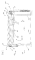
- the gate 100 is a roller shutter for opening and closing a building opening 102.
- the door 100 includes a door leaf 110 with a roller shutter 112 having, for example, a plurality of rods or louvers 114 hinged together.
- closing profile 116 In the area of a lower closing edge 117 which, in the closed position, touches the floor 103, there is a closing profile 116 on the roll hanging 112, wherein the closing profile 116 may comprise, for example, a seal and / or an anti-pinch protection.
- the gate 100 is fixed by means of a frame 104 as a stationary frame member at the edge of the building opening 102.
- the frame 104 has two guide rails 105, 106 with attached support brackets 107, 108.
- winding shaft assembly 10 When opening and closing the door 100 along the door path S of the roll hanging 112 is guided with its lateral edges in the guide rails 105, 106. On the support brackets 107, 108 a winding shaft assembly 10 is mounted.
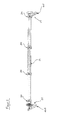
- the winding shaft assembly 10 is in the FIG. 2 further illustrated and will be explained in more detail below.
- the winding shaft assembly 10 includes a winding shaft 20 which is rotatably supported about two bearings 12 about a rotation axis D.
- the winding shaft 20 has a first end 21 and a second end 22, wherein a bearing 12 in the region of first end 21 and a bearing 12 is provided in the region of the second end.
- a plurality of drivers 26 are attached to which a winding shaft housing 24 is rotatably mounted in the form of a octagonal steel shaft.
- the driver 26 transmit the rotational movement of the rotary shaft 20 to the Drewellengephase 24.
- At this rotary shaft housing 24 of the roll hanging 112 is suitably mounted for winding the Rollbehanges 112 of the winding shaft.
- the support elements 30 are provided, which will be explained in more detail below.
- a drive device 120 is provided at the second end 23 of the winding shaft 20, which is known per se and will not be described further here.
- a weight balancer 130 is provided on the winding shaft 20, which is also known and will not be described in detail here.
- the support element 30 has an inner part 34 and an outer part 32, which are each made annular and are positively connected to each other.
- the inner part 34 comprises an annular outer wall 36 with a cross section which has a radial extent which increases in regions in the circumferential direction. This creates at a certain point of the circumference a step 39 which extends over the length of the inner part and in the radial direction has approximately a height corresponding to the thickness of the Rollbehangs.
- the outer wall 36 is integrally connected to an inner wall 38 in the region of the growing radial extent over, radially distributed over the inner circumference of the outer wall, radial webs 37.
- the inner surface of this inner wall 38 together with the inner surface of the outer wall outside the region of the growing radial extent, form the inner surface of the support element 30.
- This inner surface is in cross section to the outer shape of the Winding shaft 20 adapted adapted, so that it can be pushed onto the winding shaft 20 a positive fit.
- the outer part 32 of the support element 30 is formed, for example, by a, in relation to the radial extent of the support element, thin ring, which corresponds in cross section to the shape of the outer cross section of the inner part 34.
- the radial thickness D of the outer part 32 that is, the thickness of the outer part measured in the radial direction is preferably less than 20% than the radial thickness D of the inner part 34 in a region 40 around a recess for receiving the web 33 of the outer part 32, the having the smallest radial thickness D.
- the radial thickness D may also be less than 30% of the radial thickness D of the inner part.
- the radial thickness D of the outer part 32 is constant along the circumference of the support element 30, as in Fig. 3 is recognizable.
- the outer part 32 completely surrounds the inner part 34 along the circumference, that is to say that there are no regions along the circumference in which the inner part 34 would not be covered by the outer part 32 in a radial direction.
- the ring is connected via a plurality of webs 33 with the inner part 34, which are T-shaped and distributed over the inner circumference of the outer part.
- these webs 33 are pushed into correspondingly shaped bulges 35 of the inner part in the axial direction of the support element.
- webs and bulges may be e.g. be formed in the shape of a dovetail.
- the materials for the production of inner and outer parts 34, 32 of the support element 30 are selected so that a low abrasion on the outer part 32 with a high load capacity on the inner part 34 can be achieved.
- an existing at least two materials support element is formed.
- the material polyurethane is selected according to the outer part; but it could also be used other, abrasion resistant materials.
- the outer part 32 has a high abrasion resistance compared to the inner part.
- the outer part 32 has a corresponding elasticity, which makes it possible to compensate for micro-movements between the fins 114 of the Rollbehangs 112 and the inner part 34.
- the outer part 32 which comes into contact with the lamellae 114 of the Rollbehangs 112, a high abrasion resistance. This reduces the abrasion on the support element 30 and thus the traces of abrasion on the roll hanging 112. Further advantageously, the outer part has an elasticity which makes it possible to compensate for the micromovements described. This happens because the outer part 32 stretches or compresses along the occurring tangential forces. This results in less friction between the outer part 30 and the fins 114 of the Rollbehangs 112, which further reduces abrasion. There are also other means or properties of the outer part or Rollbehangs conceivable that further reduce the friction between the Rollbehang 112 and the support member 30 in order to reduce the abrasion on.
Landscapes
- Engineering & Computer Science (AREA)
- Structural Engineering (AREA)
- Architecture (AREA)
- Civil Engineering (AREA)
- Operating, Guiding And Securing Of Roll- Type Closing Members (AREA)
Applications Claiming Priority (1)
| Application Number | Priority Date | Filing Date | Title |
|---|---|---|---|
| DE102010043530A DE102010043530A1 (de) | 2010-11-08 | 2010-11-08 | Auflageemelent für ein Rolltor oder Rollgitter |
Publications (3)
| Publication Number | Publication Date |
|---|---|
| EP2450521A2 true EP2450521A2 (fr) | 2012-05-09 |
| EP2450521A3 EP2450521A3 (fr) | 2013-08-14 |
| EP2450521B1 EP2450521B1 (fr) | 2016-07-06 |
Family
ID=44946990
Family Applications (1)
| Application Number | Title | Priority Date | Filing Date |
|---|---|---|---|
| EP11186628.1A Active EP2450521B1 (fr) | 2010-11-08 | 2011-10-26 | Elément de support pour une porte roulante ou une grille roulante |
Country Status (2)
| Country | Link |
|---|---|
| EP (1) | EP2450521B1 (fr) |
| DE (1) | DE102010043530A1 (fr) |
Cited By (1)
| Publication number | Priority date | Publication date | Assignee | Title |
|---|---|---|---|---|
| FR3130309A1 (fr) * | 2021-12-15 | 2023-06-16 | Zurfluh Feller | Verrou de volet roulant, installation de volet roulant comprenant un tel verrou et procédé de fabrication associé |
Families Citing this family (2)
| Publication number | Priority date | Publication date | Assignee | Title |
|---|---|---|---|---|
| DE102014002387B3 (de) * | 2014-02-24 | 2015-05-07 | Selve Vermögensverwaltung GmbH & Co. KG | Vorrichtung zur Befestigung eines Rollladenpanzers an einer Wickelwelle |
| DE102019217334A1 (de) * | 2019-11-11 | 2021-05-12 | Zf Friedrichshafen Ag | Verfahren und Steuerungssystem zum Betreiben eines Antriebsstrangs |
Citations (3)
| Publication number | Priority date | Publication date | Assignee | Title |
|---|---|---|---|---|
| US2898988A (en) | 1956-11-20 | 1959-08-11 | Wilson J G Corp | Rolling metal grille to serve as a closure device for a building |
| US3693695A (en) | 1970-07-31 | 1972-09-26 | Chester A Deane | Closure construction |
| EP2131003A2 (fr) | 2008-06-04 | 2009-12-09 | Hörmann Kg Amshausen | Agencement d'arbres rotatifs pour une porte, notamment pour une porte roulante et une telle porte |
Family Cites Families (2)
| Publication number | Priority date | Publication date | Assignee | Title |
|---|---|---|---|---|
| US3348604A (en) * | 1966-05-20 | 1967-10-24 | Slick Ind Company | Window shades and shade rollers |
| FR2809095B1 (fr) * | 2000-05-17 | 2002-09-13 | Somfy | Dispositif d'accrochage d'un element enroulable sur un tube d'enroulement |
-
2010
- 2010-11-08 DE DE102010043530A patent/DE102010043530A1/de not_active Ceased
-
2011
- 2011-10-26 EP EP11186628.1A patent/EP2450521B1/fr active Active
Patent Citations (3)
| Publication number | Priority date | Publication date | Assignee | Title |
|---|---|---|---|---|
| US2898988A (en) | 1956-11-20 | 1959-08-11 | Wilson J G Corp | Rolling metal grille to serve as a closure device for a building |
| US3693695A (en) | 1970-07-31 | 1972-09-26 | Chester A Deane | Closure construction |
| EP2131003A2 (fr) | 2008-06-04 | 2009-12-09 | Hörmann Kg Amshausen | Agencement d'arbres rotatifs pour une porte, notamment pour une porte roulante et une telle porte |
Cited By (1)
| Publication number | Priority date | Publication date | Assignee | Title |
|---|---|---|---|---|
| FR3130309A1 (fr) * | 2021-12-15 | 2023-06-16 | Zurfluh Feller | Verrou de volet roulant, installation de volet roulant comprenant un tel verrou et procédé de fabrication associé |
Also Published As
| Publication number | Publication date |
|---|---|
| DE102010043530A1 (de) | 2012-05-10 |
| EP2450521B1 (fr) | 2016-07-06 |
| EP2450521A3 (fr) | 2013-08-14 |
Similar Documents
| Publication | Publication Date | Title |
|---|---|---|
| EP1948898B1 (fr) | Porte roulante industrielle a vitesse elevee | |
| EP3388610B1 (fr) | Assemblage d'arbre, dispositif de fermeture ou de protection ainsi que jeu de montage | |
| EP1954909B1 (fr) | Dispositif de compensation de poids pour porte relevable | |
| DE69935944T2 (de) | Dichtungsanordnung für ein Wälzlager | |
| EP2395195B1 (fr) | Porte additionelle, notamment porte moustiquaire, avec un mécanisme de fermeture automatique | |
| EP2317054B1 (fr) | Porte coulissante | |
| WO2000060208A1 (fr) | Porte pour l'industrie | |
| EP1510382B1 (fr) | Store à enroleur courbé pour véhicules | |
| DE69723655T2 (de) | Fallsicherungsvorrichtung für vertikal aufrollbare Verschlusseinrichtungen | |
| EP2450521B1 (fr) | Elément de support pour une porte roulante ou une grille roulante | |
| DE102014003494B4 (de) | Gebäudeöffnungsverschattungsvorrichtung und Achskappenmodul für die Wickelwelle der Gebäudeöffnungsverschattungsvorrichtung | |
| EP3763911B1 (fr) | Dispositif de rail de guidage pour un portail roulant ou un grillage roulant | |
| EP2530344B1 (fr) | Élément de roulement d'une articulation de trépied ainsi qu'articulation de trépied comprenant un tel élément de roulement | |
| DE19711318C2 (de) | Rolladen für Türen, Fenster oder dergleichen | |
| DE202013102031U1 (de) | Verschlussanordnung | |
| EP1852567B1 (fr) | Chariot | |
| EP3562999B1 (fr) | Dispositif pour déplacer une lame d'aiguille d'un aiguillage | |
| DE69408072T2 (de) | Vorrichtung zum Öffnen und Schliessen einer Klappe | |
| DE102018105242B3 (de) | Radial-schrägrollenlager | |
| EP1469159A2 (fr) | Dispositif d'étanchéité pour porte | |
| DE102015004859A1 (de) | Rollladen | |
| DE2943886A1 (de) | Tor fuer hallen, garagen o.dgl. | |
| EP1431489B1 (fr) | Charnière | |
| EP2444583B1 (fr) | Colonne de portail pour un portail roulant | |
| EP3441554A1 (fr) | Unité support pour une unité d'entraînement d'un dispositif de verrouillage ou de protection |
Legal Events
| Date | Code | Title | Description |
|---|---|---|---|
| PUAI | Public reference made under article 153(3) epc to a published international application that has entered the european phase |
Free format text: ORIGINAL CODE: 0009012 |
|
| AK | Designated contracting states |
Kind code of ref document: A2 Designated state(s): AL AT BE BG CH CY CZ DE DK EE ES FI FR GB GR HR HU IE IS IT LI LT LU LV MC MK MT NL NO PL PT RO RS SE SI SK SM TR |
|
| AX | Request for extension of the european patent |
Extension state: BA ME |
|
| PUAL | Search report despatched |
Free format text: ORIGINAL CODE: 0009013 |
|
| AK | Designated contracting states |
Kind code of ref document: A3 Designated state(s): AL AT BE BG CH CY CZ DE DK EE ES FI FR GB GR HR HU IE IS IT LI LT LU LV MC MK MT NL NO PL PT RO RS SE SI SK SM TR |
|
| AX | Request for extension of the european patent |
Extension state: BA ME |
|
| RIC1 | Information provided on ipc code assigned before grant |
Ipc: E06B 9/171 20060101AFI20130709BHEP Ipc: E06B 9/18 20060101ALI20130709BHEP |
|
| 17P | Request for examination filed |
Effective date: 20140124 |
|
| RBV | Designated contracting states (corrected) |
Designated state(s): AL AT BE BG CH CY CZ DE DK EE ES FI FR GB GR HR HU IE IS IT LI LT LU LV MC MK MT NL NO PL PT RO RS SE SI SK SM TR |
|
| GRAP | Despatch of communication of intention to grant a patent |
Free format text: ORIGINAL CODE: EPIDOSNIGR1 |
|
| RIC1 | Information provided on ipc code assigned before grant |
Ipc: E06B 9/18 20060101ALI20160210BHEP Ipc: E06B 9/171 20060101AFI20160210BHEP |
|
| INTG | Intention to grant announced |
Effective date: 20160303 |
|
| GRAS | Grant fee paid |
Free format text: ORIGINAL CODE: EPIDOSNIGR3 |
|
| GRAA | (expected) grant |
Free format text: ORIGINAL CODE: 0009210 |
|
| AK | Designated contracting states |
Kind code of ref document: B1 Designated state(s): AL AT BE BG CH CY CZ DE DK EE ES FI FR GB GR HR HU IE IS IT LI LT LU LV MC MK MT NL NO PL PT RO RS SE SI SK SM TR |
|
| REG | Reference to a national code |
Ref country code: GB Ref legal event code: FG4D Free format text: NOT ENGLISH |
|
| REG | Reference to a national code |
Ref country code: AT Ref legal event code: REF Ref document number: 810861 Country of ref document: AT Kind code of ref document: T Effective date: 20160715 Ref country code: CH Ref legal event code: EP |
|
| REG | Reference to a national code |
Ref country code: IE Ref legal event code: FG4D Free format text: LANGUAGE OF EP DOCUMENT: GERMAN |
|
| REG | Reference to a national code |
Ref country code: DE Ref legal event code: R096 Ref document number: 502011010098 Country of ref document: DE |
|
| REG | Reference to a national code |
Ref country code: FR Ref legal event code: PLFP Year of fee payment: 6 |
|
| REG | Reference to a national code |
Ref country code: NL Ref legal event code: MP Effective date: 20160706 |
|
| REG | Reference to a national code |
Ref country code: LT Ref legal event code: MG4D |
|
| PG25 | Lapsed in a contracting state [announced via postgrant information from national office to epo] |
Ref country code: NO Free format text: LAPSE BECAUSE OF FAILURE TO SUBMIT A TRANSLATION OF THE DESCRIPTION OR TO PAY THE FEE WITHIN THE PRESCRIBED TIME-LIMIT Effective date: 20161006 Ref country code: IS Free format text: LAPSE BECAUSE OF FAILURE TO SUBMIT A TRANSLATION OF THE DESCRIPTION OR TO PAY THE FEE WITHIN THE PRESCRIBED TIME-LIMIT Effective date: 20161106 Ref country code: IT Free format text: LAPSE BECAUSE OF FAILURE TO SUBMIT A TRANSLATION OF THE DESCRIPTION OR TO PAY THE FEE WITHIN THE PRESCRIBED TIME-LIMIT Effective date: 20160706 Ref country code: LT Free format text: LAPSE BECAUSE OF FAILURE TO SUBMIT A TRANSLATION OF THE DESCRIPTION OR TO PAY THE FEE WITHIN THE PRESCRIBED TIME-LIMIT Effective date: 20160706 Ref country code: NL Free format text: LAPSE BECAUSE OF FAILURE TO SUBMIT A TRANSLATION OF THE DESCRIPTION OR TO PAY THE FEE WITHIN THE PRESCRIBED TIME-LIMIT Effective date: 20160706 Ref country code: RS Free format text: LAPSE BECAUSE OF FAILURE TO SUBMIT A TRANSLATION OF THE DESCRIPTION OR TO PAY THE FEE WITHIN THE PRESCRIBED TIME-LIMIT Effective date: 20160706 Ref country code: HR Free format text: LAPSE BECAUSE OF FAILURE TO SUBMIT A TRANSLATION OF THE DESCRIPTION OR TO PAY THE FEE WITHIN THE PRESCRIBED TIME-LIMIT Effective date: 20160706 Ref country code: FI Free format text: LAPSE BECAUSE OF FAILURE TO SUBMIT A TRANSLATION OF THE DESCRIPTION OR TO PAY THE FEE WITHIN THE PRESCRIBED TIME-LIMIT Effective date: 20160706 |
|
| PG25 | Lapsed in a contracting state [announced via postgrant information from national office to epo] |
Ref country code: PL Free format text: LAPSE BECAUSE OF FAILURE TO SUBMIT A TRANSLATION OF THE DESCRIPTION OR TO PAY THE FEE WITHIN THE PRESCRIBED TIME-LIMIT Effective date: 20160706 Ref country code: GR Free format text: LAPSE BECAUSE OF FAILURE TO SUBMIT A TRANSLATION OF THE DESCRIPTION OR TO PAY THE FEE WITHIN THE PRESCRIBED TIME-LIMIT Effective date: 20161007 Ref country code: ES Free format text: LAPSE BECAUSE OF FAILURE TO SUBMIT A TRANSLATION OF THE DESCRIPTION OR TO PAY THE FEE WITHIN THE PRESCRIBED TIME-LIMIT Effective date: 20160706 Ref country code: BE Free format text: LAPSE BECAUSE OF NON-PAYMENT OF DUE FEES Effective date: 20161031 Ref country code: LV Free format text: LAPSE BECAUSE OF FAILURE TO SUBMIT A TRANSLATION OF THE DESCRIPTION OR TO PAY THE FEE WITHIN THE PRESCRIBED TIME-LIMIT Effective date: 20160706 Ref country code: PT Free format text: LAPSE BECAUSE OF FAILURE TO SUBMIT A TRANSLATION OF THE DESCRIPTION OR TO PAY THE FEE WITHIN THE PRESCRIBED TIME-LIMIT Effective date: 20161107 Ref country code: SE Free format text: LAPSE BECAUSE OF FAILURE TO SUBMIT A TRANSLATION OF THE DESCRIPTION OR TO PAY THE FEE WITHIN THE PRESCRIBED TIME-LIMIT Effective date: 20160706 |
|
| REG | Reference to a national code |
Ref country code: DE Ref legal event code: R097 Ref document number: 502011010098 Country of ref document: DE |
|
| PG25 | Lapsed in a contracting state [announced via postgrant information from national office to epo] |
Ref country code: RO Free format text: LAPSE BECAUSE OF FAILURE TO SUBMIT A TRANSLATION OF THE DESCRIPTION OR TO PAY THE FEE WITHIN THE PRESCRIBED TIME-LIMIT Effective date: 20160706 Ref country code: EE Free format text: LAPSE BECAUSE OF FAILURE TO SUBMIT A TRANSLATION OF THE DESCRIPTION OR TO PAY THE FEE WITHIN THE PRESCRIBED TIME-LIMIT Effective date: 20160706 |
|
| PLBE | No opposition filed within time limit |
Free format text: ORIGINAL CODE: 0009261 |
|
| STAA | Information on the status of an ep patent application or granted ep patent |
Free format text: STATUS: NO OPPOSITION FILED WITHIN TIME LIMIT |
|
| PG25 | Lapsed in a contracting state [announced via postgrant information from national office to epo] |
Ref country code: CZ Free format text: LAPSE BECAUSE OF FAILURE TO SUBMIT A TRANSLATION OF THE DESCRIPTION OR TO PAY THE FEE WITHIN THE PRESCRIBED TIME-LIMIT Effective date: 20160706 Ref country code: SK Free format text: LAPSE BECAUSE OF FAILURE TO SUBMIT A TRANSLATION OF THE DESCRIPTION OR TO PAY THE FEE WITHIN THE PRESCRIBED TIME-LIMIT Effective date: 20160706 Ref country code: BG Free format text: LAPSE BECAUSE OF FAILURE TO SUBMIT A TRANSLATION OF THE DESCRIPTION OR TO PAY THE FEE WITHIN THE PRESCRIBED TIME-LIMIT Effective date: 20161006 Ref country code: SM Free format text: LAPSE BECAUSE OF FAILURE TO SUBMIT A TRANSLATION OF THE DESCRIPTION OR TO PAY THE FEE WITHIN THE PRESCRIBED TIME-LIMIT Effective date: 20160706 Ref country code: DK Free format text: LAPSE BECAUSE OF FAILURE TO SUBMIT A TRANSLATION OF THE DESCRIPTION OR TO PAY THE FEE WITHIN THE PRESCRIBED TIME-LIMIT Effective date: 20160706 |
|
| REG | Reference to a national code |
Ref country code: CH Ref legal event code: PL |
|
| 26N | No opposition filed |
Effective date: 20170407 |
|
| REG | Reference to a national code |
Ref country code: IE Ref legal event code: MM4A |
|
| PG25 | Lapsed in a contracting state [announced via postgrant information from national office to epo] |
Ref country code: LI Free format text: LAPSE BECAUSE OF NON-PAYMENT OF DUE FEES Effective date: 20161031 Ref country code: CH Free format text: LAPSE BECAUSE OF NON-PAYMENT OF DUE FEES Effective date: 20161031 |
|
| PG25 | Lapsed in a contracting state [announced via postgrant information from national office to epo] |
Ref country code: SI Free format text: LAPSE BECAUSE OF FAILURE TO SUBMIT A TRANSLATION OF THE DESCRIPTION OR TO PAY THE FEE WITHIN THE PRESCRIBED TIME-LIMIT Effective date: 20160706 Ref country code: LU Free format text: LAPSE BECAUSE OF NON-PAYMENT OF DUE FEES Effective date: 20161026 |
|
| REG | Reference to a national code |
Ref country code: FR Ref legal event code: PLFP Year of fee payment: 7 |
|
| PG25 | Lapsed in a contracting state [announced via postgrant information from national office to epo] |
Ref country code: IE Free format text: LAPSE BECAUSE OF NON-PAYMENT OF DUE FEES Effective date: 20161026 |
|
| REG | Reference to a national code |
Ref country code: BE Ref legal event code: MM Effective date: 20161031 |
|
| PG25 | Lapsed in a contracting state [announced via postgrant information from national office to epo] |
Ref country code: CY Free format text: LAPSE BECAUSE OF FAILURE TO SUBMIT A TRANSLATION OF THE DESCRIPTION OR TO PAY THE FEE WITHIN THE PRESCRIBED TIME-LIMIT Effective date: 20160706 Ref country code: HU Free format text: LAPSE BECAUSE OF FAILURE TO SUBMIT A TRANSLATION OF THE DESCRIPTION OR TO PAY THE FEE WITHIN THE PRESCRIBED TIME-LIMIT; INVALID AB INITIO Effective date: 20111026 |
|
| PG25 | Lapsed in a contracting state [announced via postgrant information from national office to epo] |
Ref country code: MC Free format text: LAPSE BECAUSE OF FAILURE TO SUBMIT A TRANSLATION OF THE DESCRIPTION OR TO PAY THE FEE WITHIN THE PRESCRIBED TIME-LIMIT Effective date: 20160706 Ref country code: TR Free format text: LAPSE BECAUSE OF FAILURE TO SUBMIT A TRANSLATION OF THE DESCRIPTION OR TO PAY THE FEE WITHIN THE PRESCRIBED TIME-LIMIT Effective date: 20160706 Ref country code: MT Free format text: LAPSE BECAUSE OF FAILURE TO SUBMIT A TRANSLATION OF THE DESCRIPTION OR TO PAY THE FEE WITHIN THE PRESCRIBED TIME-LIMIT Effective date: 20160706 Ref country code: MK Free format text: LAPSE BECAUSE OF FAILURE TO SUBMIT A TRANSLATION OF THE DESCRIPTION OR TO PAY THE FEE WITHIN THE PRESCRIBED TIME-LIMIT Effective date: 20160706 |
|
| REG | Reference to a national code |
Ref country code: FR Ref legal event code: PLFP Year of fee payment: 8 |
|
| PG25 | Lapsed in a contracting state [announced via postgrant information from national office to epo] |
Ref country code: AL Free format text: LAPSE BECAUSE OF FAILURE TO SUBMIT A TRANSLATION OF THE DESCRIPTION OR TO PAY THE FEE WITHIN THE PRESCRIBED TIME-LIMIT Effective date: 20160706 |
|
| P01 | Opt-out of the competence of the unified patent court (upc) registered |
Effective date: 20230512 |
|
| PGFP | Annual fee paid to national office [announced via postgrant information from national office to epo] |
Ref country code: GB Payment date: 20251029 Year of fee payment: 15 |
|
| PGFP | Annual fee paid to national office [announced via postgrant information from national office to epo] |
Ref country code: AT Payment date: 20251024 Year of fee payment: 15 |
|
| PGFP | Annual fee paid to national office [announced via postgrant information from national office to epo] |
Ref country code: FR Payment date: 20251024 Year of fee payment: 15 |
|
| PGFP | Annual fee paid to national office [announced via postgrant information from national office to epo] |
Ref country code: DE Payment date: 20251222 Year of fee payment: 15 |