EP2450636A2 - Elément de support de revêtement de sol et agencement de revêtement de sol doté d'un élément de support de revêtement de sol - Google Patents
Elément de support de revêtement de sol et agencement de revêtement de sol doté d'un élément de support de revêtement de sol Download PDFInfo
- Publication number
- EP2450636A2 EP2450636A2 EP20110188246 EP11188246A EP2450636A2 EP 2450636 A2 EP2450636 A2 EP 2450636A2 EP 20110188246 EP20110188246 EP 20110188246 EP 11188246 A EP11188246 A EP 11188246A EP 2450636 A2 EP2450636 A2 EP 2450636A2
- Authority
- EP
- European Patent Office
- Prior art keywords
- plastic sheet
- floor covering
- profiled plastic
- support element
- adhesive
- Prior art date
- Legal status (The legal status is an assumption and is not a legal conclusion. Google has not performed a legal analysis and makes no representation as to the accuracy of the status listed.)
- Withdrawn
Links
Images

Classifications
-
- F—MECHANICAL ENGINEERING; LIGHTING; HEATING; WEAPONS; BLASTING
- F24—HEATING; RANGES; VENTILATING
- F24D—DOMESTIC- OR SPACE-HEATING SYSTEMS, e.g. CENTRAL HEATING SYSTEMS; DOMESTIC HOT-WATER SUPPLY SYSTEMS; ELEMENTS OR COMPONENTS THEREFOR
- F24D3/00—Hot-water central heating systems
- F24D3/12—Tube and panel arrangements for ceiling, wall, or underfloor heating
- F24D3/14—Tube and panel arrangements for ceiling, wall, or underfloor heating incorporated in a ceiling, wall or floor
- F24D3/141—Tube mountings specially adapted therefor
- F24D3/142—Tube mountings specially adapted therefor integrated in prefab construction elements
-
- E—FIXED CONSTRUCTIONS
- E04—BUILDING
- E04F—FINISHING WORK ON BUILDINGS, e.g. STAIRS, FLOORS
- E04F15/00—Flooring
- E04F15/18—Separately-laid insulating layers; Other additional insulating measures; Floating floors
- E04F15/182—Underlayers coated with adhesive or mortar to receive the flooring
-
- E—FIXED CONSTRUCTIONS
- E04—BUILDING
- E04F—FINISHING WORK ON BUILDINGS, e.g. STAIRS, FLOORS
- E04F15/00—Flooring
- E04F15/18—Separately-laid insulating layers; Other additional insulating measures; Floating floors
- E04F15/185—Underlayers in the form of studded or ribbed plates
-
- E—FIXED CONSTRUCTIONS
- E04—BUILDING
- E04F—FINISHING WORK ON BUILDINGS, e.g. STAIRS, FLOORS
- E04F15/00—Flooring
- E04F15/18—Separately-laid insulating layers; Other additional insulating measures; Floating floors
- E04F15/186—Underlayers covered with a mesh or the like
-
- Y—GENERAL TAGGING OF NEW TECHNOLOGICAL DEVELOPMENTS; GENERAL TAGGING OF CROSS-SECTIONAL TECHNOLOGIES SPANNING OVER SEVERAL SECTIONS OF THE IPC; TECHNICAL SUBJECTS COVERED BY FORMER USPC CROSS-REFERENCE ART COLLECTIONS [XRACs] AND DIGESTS
- Y02—TECHNOLOGIES OR APPLICATIONS FOR MITIGATION OR ADAPTATION AGAINST CLIMATE CHANGE
- Y02B—CLIMATE CHANGE MITIGATION TECHNOLOGIES RELATED TO BUILDINGS, e.g. HOUSING, HOUSE APPLIANCES OR RELATED END-USER APPLICATIONS
- Y02B30/00—Energy efficient heating, ventilation or air conditioning [HVAC]
Definitions
- the invention relates to a floor covering support element, on which a walkable surface covering can be laid, with a profiled plastic sheet and with a mesh fabric arranged on an upper side of the profiled plastic sheet.
- a rigid and highly resilient substrate as it is formed for example by a concrete slab or a sufficiently thick layer of screed, formed from tiles or other plate coverings walkable surface coating can be laid directly and fixed with the help of an adhesive or adhesive mortar.
- the height required for the surface covering is in such cases only slightly larger than the thickness of the laid surface covering or the tiles or the surface covering plates. In many cases, the installation height should be as small as possible in order to allow a flush connection to adjacent floor coverings, door sills or door openings under given spatial conditions.
- a walk-on surface covering is to be laid on a substrate which is not sufficiently rigid or load-bearing, an intermediate layer which can be subjected to mechanical stress under the surface covering must as a rule be required are arranged, which forms a solid support structure for the individual tiles or covering plates of the surface covering.
- a reinforcing arrangement which has a substantially planar support made of thin, metallic strip material or sheet metal, which can be arranged, for example, on foam plastic plates which have been laid on an underground for improved thermal or acoustic insulation.
- the planar carrier made of a metallic strip material has on an upper side anchoring means, which can ensure a positive and / or cohesive connection with a mortar or adhesive layer.
- the tiles or other surface cover plates can be embedded.
- the metallic carrier form with the mortar or adhesive layer a high-strength composite, which spreads a spatially concentrated stress on the surface covering a large area on the underlying plastic foam plates and thereby prevents the foam plastic plates are selectively pressed and damaged.
- foam plastic plates or other comparable plate-shaped covering elements required for underfloor heating heat-transferring elements can be arranged. From practice it is known that in the foam plastic plates groove-shaped receiving channels are formed, in which pipes can be arranged, which can be traversed by a heat medium.
- a heat medium for example, water may be used that heats with a low-temperature heater has been. As the heated water flows through the pipes, the heated water releases heat into the surrounding areas of the flooring assembly.
- a flooring arrangement in which a preferably fleece-like decoupling layer is arranged on plate-shaped covering elements, in which a floor heating may be embedded, which forms a mechanical decoupling between the plate-shaped covering elements and a walk-on surface covering arranged thereon.
- a hardening filling compound applied from the top to the reinforcing layer and the grid-like structural element forms a mechanically stable bond with the grid-like structural element and the glass fiber fabric on which the surface covering can be arranged.
- non-woven decoupling layer Due to the non-woven decoupling layer can be achieved that the occurring during operation of the underfloor heating alternating stresses and strains in the plate-shaped covering elements are largely decoupled from the surface covering thereon.
- the use of a nonwoven decoupling layer in conjunction with latticed structural elements and a reinforcing layer is costly to manufacture and process.
- a bottom of the profiled plastic sheet at least partially has an adhesive coating.
- the floor covering support element can be laid directly on a substrate, or on an upper side of plate-shaped floor covering elements with an embedded underfloor heating device. Due to the adhesive coating, the floor covering support element is in fixed to the predetermined position. The laying of several adjoining floor covering support elements which form a full-surface floor covering layer is thereby considerably facilitated.
- the adhesive coating forms a self-adhesive mounting fixation. The use of a drying adhesive mortar, as known in the art is not required, so that a short laying time is made possible.
- Such a floor covering support element can be produced quickly and inexpensively in a simple manner.
- the profiled plastic sheet can be produced for example by deep drawing or extrusion of a suitable plastic material and provided in a subsequent operation on the bottom with an adhesive coating and on the top with a glued grid fabric.
- the adhesive coating may consist of a permanently elastic or permanently elastic adhesive.
- a permanently elastic or permanently elastic adhesive During the laying of the floor covering support elements and the surface covering arranged thereon, a sufficient mounting fixation facilitating the laying is ensured. Subsequently, the permanently elastic or permanently elastic adhesive allows low-stress compensation between the adjacent layers of the floor covering, which can expand or contract to different degrees due to different thermal expansion properties in a heating or cooling.
- the adhesive coating consists of an adhesive which good adhesive properties on a surface made of metal, plastic or a metallic coating guaranteed.
- the covering elements usually have, for example, a metallic coating or a thin aluminum plate arranged on a plastic plate in order to distribute the heat emitted over the heating pipes embedded thereon over a large area and as efficiently as possible in the direction of the surface covering.
- the flooring elements should be as simple, quick and reliable as possible with the help of the adhesive coating on the flooring elements with the underfloor heating and set at least for the duration of installation of the flooring arrangement.
- the profiled plastic sheet has a three-dimensionally structured top that provides sufficient support to a tile adhesive or adhesive mortar distributed thereon.
- a tile adhesive or adhesive mortar distributed thereon.
- the profiled plastic web has strip-shaped and parallel aligned elevations and depressions.
- the strip-shaped elevations and depressions form channel-like structures.
- the respectively used filling compound for example a tile adhesive or an adhesive mortar, can penetrate into the strip-shaped depressions and form a positive engagement with the profiled plastic sheet.
- From an underside of the strip-shaped elevations form ventilation ducts into which the applied on the top of the profiled plastic sheet filling material does not penetrate and in which heated air can circulate. In this way, the exiting from the pipes heat can be distributed over the ventilation channels over a large area and transferred evenly to the superimposed surface covering.
- the profiled plastic web has mutually aligned groove-shaped channels.
- the strip-shaped or meander-shaped, for example, alternately arranged on the top or the bottom groove-shaped channels form either viewed from above recesses, which form an intimate and positive connection with the filling material arranged thereon on top of profiled plastic sheet, or arranged on the bottom ventilation ducts, which promote an even distribution of heat transmitted through the pipes heat.
- a support surface of the underside of the profiled plastic strip is substantially completely covered with an adhesive coating.
- the strip-shaped or channel-shaped elevations and depressions of the profiled plastic sheet form with the sections extending along the underside in each case regions in which the profiled plastic sheet rests flush on a substrate.
- the sections extending along the underside form a support surface of the underside, which rests flat on the substrate or on plate-shaped covering elements.
- the adhesive coating can be applied to this bearing surface by means of suitable transfer rollers.
- the profiled plastic sheet has liquid-permeable recesses.
- the liquid-permeable recesses favor a rapid heating and drying of the applied from above on the profiled plastic sheet filling material, so that a short drying time and rapid curing and subsequent use of the filling compound, or the embedded surface covering is made possible.
- the known from the prior art disadvantages of a liquid-impermeable Moisture barrier located immediately below the surface covering can be avoided in this way.
- the recesses are arranged in the region of depressions and, at least in sections, flush with an underside of the profiled plastic sheet.
- the recesses can be produced in a cost-effective and time-consuming manner following a deep-drawing process or an extrusion of the profiled plastic sheet by punching, cutting or one-sided milling.
- the coating with an adhesive layer is expediently carried out only after the formation of the recesses.
- the arrangement of the recesses in a lower region or on the underside of the profiled plastic sheet ensures effective ventilation of the profiled plastic sheet and the flooring layers arranged thereon, so that rapid heat exchange and the avoidance of waterlogging are favored.
- the profiled plastic sheet Due to the three-dimensionally structured surface of the profiled plastic sheet, a sufficiently dimensionally stable and mechanically strong connection between the profiled plastic sheet and a thin layer of a tile adhesive or an adhesive mortar distributed thereon is already ensured in many cases.
- the thickness of the layer formed from the tile adhesive or adhesive mortar must only be sufficiently large to cover the three-dimensionally structured surface of the profiled plastic sheet and also to allow embedding of the surface covering.
- the mesh fabric is determined in regions on the profiled plastic sheet.
- the filler material penetrates and surrounds the mesh fabric and thereby forms a dimensionally stable bond with the mesh fabric, which ensures a reliable bond between the mesh fabric and the filler even under thermal stress and consequent expansion or contraction.
- the mesh fabric is glued with a permanently elastic or permanently elastic adhesive with the profiled plastic sheet.
- the profiled plastic sheet is glued with a permanently elastic or permanently elastic adhesive with the plate-shaped covering elements arranged underneath.
- the invention also relates to a floor covering arrangement with a floor covering support element on which a walkable surface covering can be laid, wherein the floor covering support element has a profiled plastic web with a mesh fabric arranged on an upper side of the profiled plastic sheet and with an adhesive coating arranged at least in regions on an underside of the profiled plastic sheet.
- the floor covering arrangement has plate-like covering elements which can be laid on a substrate and have groove-shaped receiving channels for pipelines, through which a heat medium can flow.
- the covering elements have groove-shaped receiving channels into which the pipelines can be inserted and embedded flush with a surface of the covering elements.
- the plate-shaped covering elements on a top side facing the profiled plastic sheet have a covering layer of a material which conducts heat well.
- Suitable heat-conducting Materials are for example metal and in terms of material and manufacturing costs, in particular aluminum.
- plate-shaped covering element consists of a lightweight construction material with thermal insulating effect. Suitable materials include foamed plastics, which have a low weight, a sufficient mechanical strength and a thermal insulating effect.
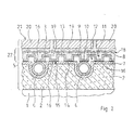
- FIGS. 1 and 2 illustrated embodiment are directly on a substrate 1 abutting several plate-shaped covering elements 2 laid.
- the plate-shaped covering elements 2 which consist of a foam plastic material and have an insulating effect to the substrate 1 out, meander-shaped receiving channels 3 are formed.
- the groove-shaped receiving channels 3 pipelines 4 are laid, which are flowed through by a heat medium and thereby can give off heat to adjacent layers of a flooring arrangement 5.
- the plate-shaped covering elements 2 have on their upper side 6 a metallic coating or a thin aluminum sheet 7, which distributes the heat transferred from the pipes 4 over a large area.
- a profiled plastic sheet 8 is arranged on the plate-shaped covering elements 2.
- the profiled plastic sheet 8 is made of a dimensionally stable plastic material, for example by deep drawing or by an extrusion process.
- the profiled plastic sheet 8 may have a sufficiently thick cross-sectional area, so that the profiled plastic sheet 8 is dimensionally stable and can be stored in the form of flat sheets or plates and distributed on the plate-shaped covering elements 2. It is also conceivable that the profiled plastic sheet 8 is made of a sufficiently thin plastic material, so that the profiled plastic sheet 8 produced quasi endless, rolled up and can be designed like a web on the plate-shaped covering elements 2.
- the profiled plastic sheet 8 has strip-shaped and parallel elevations 9 and depressions 10.
- the elevations 9 and the recesses 10 each form groove-shaped channels 11, 12, which are formed starting from an upper side 13 or from an underside 14 of the profiled plastic sheet 8, starting in the profiled plastic sheet 8.
- the support surface 15 is completely covered with an adhesive coating 16.
- the surface applied adhesive 16 is a suitable permanently plastic adhesive.
- the profiled plastic sheet 8 is fixed during the laying process on the plate-shaped covering elements 2.
- a bumpless or overlapping arrangement and alignment of adjacent profiled plastic sheets 8, which substantially completely cover a predetermined bottom surface and form a support layer for a surface covering arranged thereon, is thereby facilitated. Since no embedding in adhesive mortar or the like is required, the profiled plastic sheets 8 can be laid by an installer or by a skilled person on the plate-shaped covering elements 2. A laying by a tiler is not required.
- profiled plastic sheet 8 are also perpendicular to an orientation of the groove-shaped channels 11, 12 also strip-shaped recesses 17 formed on the underside 14 of the profiled plastic sheet 8.
- the strip-shaped recesses 17 form ventilation openings, so that heated air from the Bottom 14 of the profiled plastic sheet 8 can have a direct contact with the layers above the flooring arrangement 5.
- a lattice-shaped fabric 18 is disposed of a glass fiber reinforced plastic material.
- the grid-shaped fabric 18 is fixed at least in regions by means of a suitable adhesive on the profiled plastic sheet 8.
- a thin layer of adhesive mortar 19 is applied on the profiled plastic sheet 8.
- the adhesive mortar 19 penetrates and surrounds the grid-like fabric 18 and penetrates from above into the recesses 10 of the profiled plastic sheet 8.
- the adhesive mortar 19 forms with the lattice-like fabric 18 a mechanically extremely stable and resilient composite, which is positively engaged with the profiled plastic sheet 8 and is connected.
- the formed on the bottom 14 of the profiled plastic sheet 8 groove-shaped channels 12 are not filled by the adhesive mortar 19 and favor a distribution of heated air over the covered with the profiled plastic sheet 8 surface 6 of the plate-shaped covering elements. 2
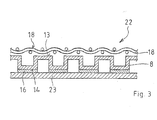
- Fig. 3 is that in the Fig. 1 and 2 shown as part of a flooring arrangement 5 flooring support member 22 enlarged shown in a sectional view.
- the adhesive coating 16 on the underside 14 of the profiled plastic sheet 8 is covered with a protective film 23 made of a suitable silicone material.
- the protective film 23 prevents adhesive bonding of the underside 14 coated with the adhesive 16 to an adjacent surface.
- only the protective film 23 has to be removed and the floor covering support element has to be arranged in the desired position and fixed by a sufficient contact pressure.
Landscapes
- Engineering & Computer Science (AREA)
- Architecture (AREA)
- Civil Engineering (AREA)
- Structural Engineering (AREA)
- Physics & Mathematics (AREA)
- Thermal Sciences (AREA)
- Chemical & Material Sciences (AREA)
- Combustion & Propulsion (AREA)
- Mechanical Engineering (AREA)
- General Engineering & Computer Science (AREA)
- Floor Finish (AREA)
Applications Claiming Priority (1)
| Application Number | Priority Date | Filing Date | Title |
|---|---|---|---|
| DE202010008978U DE202010008978U1 (de) | 2010-11-08 | 2010-11-08 | Bodenbelagsträgerelement und Bodenbelagsanordnung mit Bodenträgerelement |
Publications (2)
| Publication Number | Publication Date |
|---|---|
| EP2450636A2 true EP2450636A2 (fr) | 2012-05-09 |
| EP2450636A3 EP2450636A3 (fr) | 2015-04-08 |
Family
ID=45470259
Family Applications (1)
| Application Number | Title | Priority Date | Filing Date |
|---|---|---|---|
| EP20110188246 Withdrawn EP2450636A3 (fr) | 2010-11-08 | 2011-11-08 | Elément de support de revêtement de sol et agencement de revêtement de sol doté d'un élément de support de revêtement de sol |
Country Status (2)
| Country | Link |
|---|---|
| EP (1) | EP2450636A3 (fr) |
| DE (1) | DE202010008978U1 (fr) |
Families Citing this family (2)
| Publication number | Priority date | Publication date | Assignee | Title |
|---|---|---|---|---|
| DE102013100361A1 (de) * | 2013-01-15 | 2014-07-17 | Sandro Thronicke | Zwischenschicht für eine Belagskonstruktion |
| FR3013369B1 (fr) * | 2013-11-19 | 2016-10-21 | Soprema | Dispositif de plancher composite et son procede de realisation |
Citations (3)
| Publication number | Priority date | Publication date | Assignee | Title |
|---|---|---|---|---|
| DE20316204U1 (de) | 2003-10-22 | 2005-03-03 | Gutjahr, Walter | Bewehrungsanordnung für steife, hoch belastbare Oberflächenbeläge auf flächigen Untergründen, insbesondere für Platten- oder Fliesenbeläge |
| DE202006015397U1 (de) | 2006-10-04 | 2006-12-07 | Blanke Gmbh & Co. Kg | Mehrschichtiges Aufbausystem für Bodenbeläge bei Fußbodenheizungen |
| DE202008002169U1 (de) * | 2008-02-16 | 2008-08-21 | Grünenwald, Andreas | Einbauverbundsystem |
Family Cites Families (10)
| Publication number | Priority date | Publication date | Assignee | Title |
|---|---|---|---|---|
| DE3823578A1 (de) * | 1987-07-28 | 1989-02-09 | Lothar Ing Grad Eckert | Rohrhalterungsband und verfahren und vorrichtung zur herstellung desselben |
| DE29812219U1 (de) * | 1998-07-09 | 2000-01-13 | Elektro Bau GmbH, 79112 Freiburg | Wärmeboden mit doppelseitigem Klebeband |
| DE29915866U1 (de) * | 1999-01-15 | 2000-05-31 | Gutjahr, Walter, 64404 Bickenbach | Drainagebahn |
| EP1201848A3 (fr) * | 2000-10-24 | 2003-01-02 | Walter Gutjahr | Couche support de revêtements de sol pour l'absorbtion du son, spécialement pour carrelages |
| DE20020316U1 (de) * | 2000-10-24 | 2002-03-07 | Gutjahr, Walter, 64404 Bickenbach | Schalldämmende Trägerbahn für Bodenbeläge, insbesondere Plattenbeläge |
| DE20209869U1 (de) * | 2002-06-26 | 2003-10-30 | Gutjahr, Walter, 64404 Bickenbach | Bahn- oder Plattenmaterial aus Kunststoff als Träger für Platten- oder Fliesenbeläge |
| DE102006035135B4 (de) * | 2006-07-29 | 2021-02-18 | Oxiegen Gmbh | Noppenbauelement |
| GB0618026D0 (en) * | 2006-09-13 | 2006-10-25 | Saunders Stuart E | Tiling system |
| NO335243B1 (no) * | 2008-01-08 | 2014-10-27 | Isola As | Knasteplate, samt anvendelse og fremgangsmåte for legging av et gulvbelegg ved bruk av en slik knasteplate. |
| DE102008055978A1 (de) * | 2008-11-05 | 2010-05-06 | Brecht, Wido E. | Platten-Unterbau zum flächigen Verlegen von Rohrleitungen für Heiz- Kühl- oder Absorberzwecke, zum Beispiel für Fußboden- oder Wandheizungen sowie Verfahren zur Herstellung einer solchen Heizung |
-
2010
- 2010-11-08 DE DE202010008978U patent/DE202010008978U1/de not_active Expired - Lifetime
-
2011
- 2011-11-08 EP EP20110188246 patent/EP2450636A3/fr not_active Withdrawn
Patent Citations (3)
| Publication number | Priority date | Publication date | Assignee | Title |
|---|---|---|---|---|
| DE20316204U1 (de) | 2003-10-22 | 2005-03-03 | Gutjahr, Walter | Bewehrungsanordnung für steife, hoch belastbare Oberflächenbeläge auf flächigen Untergründen, insbesondere für Platten- oder Fliesenbeläge |
| DE202006015397U1 (de) | 2006-10-04 | 2006-12-07 | Blanke Gmbh & Co. Kg | Mehrschichtiges Aufbausystem für Bodenbeläge bei Fußbodenheizungen |
| DE202008002169U1 (de) * | 2008-02-16 | 2008-08-21 | Grünenwald, Andreas | Einbauverbundsystem |
Also Published As
| Publication number | Publication date |
|---|---|
| DE202010008978U1 (de) | 2012-02-09 |
| EP2450636A3 (fr) | 2015-04-08 |
Similar Documents
| Publication | Publication Date | Title |
|---|---|---|
| EP1911905B1 (fr) | Système de construction multicouche pour revêtements de sol pour chauffages par le sol | |
| EP0275454B1 (fr) | Feuille de matière synthétique pour un revêtement isolant de parois | |
| EP3128103B1 (fr) | Tapis de desolidarisation | |
| DE202010009133U1 (de) | Klett-Faserplatte | |
| EP2128353A1 (fr) | Elément de construction préfabriqué doté de poutres en bois et de tuyaux de chauffage intégrés | |
| EP1462727B1 (fr) | Dispositif pour la pose de tubes traversés par des fluides réfrigérants ou chauffants d'un système de conditionnement thermique à grande surface | |
| EP1697600B1 (fr) | Systeme multicouche de desolidarisation, d'etancheification et de drainage | |
| AT511073A4 (de) | Fassadenkonstruktion zur Wärmedämmung und Verkleidung von Gebäudeaußenwänden sowie Verfahren zur Herstellung einer solchen Fassadenkonstruktion | |
| CH617999A5 (en) | Plate-shaped structural element for radiant heating systems | |
| DE102004026652B4 (de) | Mehrschichtiges Entkopplungs- und Abdichtungssystem | |
| DE3919862A1 (de) | Verlorene schalungen | |
| DE102012005655A1 (de) | Verfahren zur Herstellung einer Flächenheizung | |
| DE202010008978U1 (de) | Bodenbelagsträgerelement und Bodenbelagsanordnung mit Bodenträgerelement | |
| EP1529141B1 (fr) | Procède de rénovation de surfaces extérieures de bâtiments et matériau en bande ou en plaque nécessaire à la mise en oeuvre de ce procédé | |
| EP2703741A1 (fr) | Agrégat de plaques et procédé de fabrication dýun agrégat de plaques | |
| EP1905920B1 (fr) | Plancher avec plancher chauffant | |
| EP1918483A2 (fr) | Système de découplage et drainage multicouche | |
| DE102010015635B3 (de) | Pflanzenanzuchttisch | |
| DE202014104792U1 (de) | Trägeranordnung für elektrische Heizkabel einer Flächenheizung | |
| DE10322433A1 (de) | Verfahren zur Sanierung oder vorsorglichem Schützen von durchfeuchteten äußeren Wärmedämm-Verbundsystemen oder in anderer Weise beschädigten Gebäude-Außenwänden, sowie Bahn- oder Plattenmaterial zur Durchführung des Verfahrens | |
| DE102004026651A1 (de) | Mehrschichtiges Entkopplungs-, Abdichtungs- und Drainagesystem | |
| EP1516976B1 (fr) | Elément multicouche de revêtement de sol avec des rainures pour des profilés d'assemblage | |
| EP2479358B1 (fr) | Procédé destiné à la fabrication d'un sol en préfabriqué | |
| DE10317269A1 (de) | Anordnung eines Fußbodens und Verfahren zu seiner Herstellung | |
| EP1612345A1 (fr) | Matériau de renforcement pour toits et pour surfaces de bâtiments, et procédé pour former une couche d'étanchéité |
Legal Events
| Date | Code | Title | Description |
|---|---|---|---|
| PUAI | Public reference made under article 153(3) epc to a published international application that has entered the european phase |
Free format text: ORIGINAL CODE: 0009012 |
|
| AK | Designated contracting states |
Kind code of ref document: A2 Designated state(s): AL AT BE BG CH CY CZ DE DK EE ES FI FR GB GR HR HU IE IS IT LI LT LU LV MC MK MT NL NO PL PT RO RS SE SI SK SM TR |
|
| AX | Request for extension of the european patent |
Extension state: BA ME |
|
| RIN1 | Information on inventor provided before grant (corrected) |
Inventor name: THRONICKE, SANDRO Inventor name: GUTJAHR, WALTER Inventor name: LAMMERING, WILFRIED Inventor name: HEUSER, THOMAS |
|
| PUAL | Search report despatched |
Free format text: ORIGINAL CODE: 0009013 |
|
| AK | Designated contracting states |
Kind code of ref document: A3 Designated state(s): AL AT BE BG CH CY CZ DE DK EE ES FI FR GB GR HR HU IE IS IT LI LT LU LV MC MK MT NL NO PL PT RO RS SE SI SK SM TR |
|
| AX | Request for extension of the european patent |
Extension state: BA ME |
|
| RIC1 | Information provided on ipc code assigned before grant |
Ipc: F24D 3/14 20060101AFI20150305BHEP Ipc: E04F 15/18 20060101ALI20150305BHEP |
|
| 17P | Request for examination filed |
Effective date: 20151008 |
|
| RBV | Designated contracting states (corrected) |
Designated state(s): AL AT BE BG CH CY CZ DE DK EE ES FI FR GB GR HR HU IE IS IT LI LT LU LV MC MK MT NL NO PL PT RO RS SE SI SK SM TR |
|
| RAP1 | Party data changed (applicant data changed or rights of an application transferred) |
Owner name: HEROTEC GMBH FLAECHENHEIZUNG Owner name: ARDEX ANLAGEN GMBH |
|
| 17Q | First examination report despatched |
Effective date: 20160229 |
|
| RIN1 | Information on inventor provided before grant (corrected) |
Inventor name: GUTJAHR, WALTER Inventor name: THRONICKE, SANDRO Inventor name: HEUSER, THOMAS Inventor name: LAMMERING, WILFRIED |
|
| GRAP | Despatch of communication of intention to grant a patent |
Free format text: ORIGINAL CODE: EPIDOSNIGR1 |
|
| INTG | Intention to grant announced |
Effective date: 20170821 |
|
| STAA | Information on the status of an ep patent application or granted ep patent |
Free format text: STATUS: THE APPLICATION IS DEEMED TO BE WITHDRAWN |
|
| 18D | Application deemed to be withdrawn |
Effective date: 20180103 |