EP2451225B1 - Leistungsbenachrichtigungsverfahren in einem drahtlosen Kommunikationssystem - Google Patents
Leistungsbenachrichtigungsverfahren in einem drahtlosen Kommunikationssystem Download PDFInfo
- Publication number
- EP2451225B1 EP2451225B1 EP11187596.9A EP11187596A EP2451225B1 EP 2451225 B1 EP2451225 B1 EP 2451225B1 EP 11187596 A EP11187596 A EP 11187596A EP 2451225 B1 EP2451225 B1 EP 2451225B1
- Authority
- EP
- European Patent Office
- Prior art keywords
- output power
- maximum output
- reporting
- component carrier
- uplink component
- Prior art date
- Legal status (The legal status is an assumption and is not a legal conclusion. Google has not performed a legal analysis and makes no representation as to the accuracy of the status listed.)
- Active
Links
Images






Classifications
-
- H—ELECTRICITY
- H04—ELECTRIC COMMUNICATION TECHNIQUE
- H04W—WIRELESS COMMUNICATION NETWORKS
- H04W24/00—Supervisory, monitoring or testing arrangements
- H04W24/10—Scheduling measurement reports ; Arrangements for measurement reports
-
- H—ELECTRICITY
- H04—ELECTRIC COMMUNICATION TECHNIQUE
- H04J—MULTIPLEX COMMUNICATION
- H04J11/00—Orthogonal multiplex systems, e.g. using WALSH codes
-
- H—ELECTRICITY
- H04—ELECTRIC COMMUNICATION TECHNIQUE
- H04W—WIRELESS COMMUNICATION NETWORKS
- H04W52/00—Power management, e.g. Transmission Power Control [TPC] or power classes
- H04W52/04—Transmission power control [TPC]
- H04W52/30—Transmission power control [TPC] using constraints in the total amount of available transmission power
- H04W52/34—TPC management, i.e. sharing limited amount of power among users or channels or data types, e.g. cell loading
-
- H—ELECTRICITY
- H04—ELECTRIC COMMUNICATION TECHNIQUE
- H04W—WIRELESS COMMUNICATION NETWORKS
- H04W52/00—Power management, e.g. Transmission Power Control [TPC] or power classes
- H04W52/04—Transmission power control [TPC]
- H04W52/30—Transmission power control [TPC] using constraints in the total amount of available transmission power
- H04W52/36—Transmission power control [TPC] using constraints in the total amount of available transmission power with a discrete range or set of values, e.g. step size, ramping or offsets
- H04W52/365—Power headroom reporting
-
- H—ELECTRICITY
- H04—ELECTRIC COMMUNICATION TECHNIQUE
- H04W—WIRELESS COMMUNICATION NETWORKS
- H04W52/00—Power management, e.g. Transmission Power Control [TPC] or power classes
- H04W52/04—Transmission power control [TPC]
- H04W52/30—Transmission power control [TPC] using constraints in the total amount of available transmission power
- H04W52/36—Transmission power control [TPC] using constraints in the total amount of available transmission power with a discrete range or set of values, e.g. step size, ramping or offsets
- H04W52/367—Power values between minimum and maximum limits, e.g. dynamic range
-
- H—ELECTRICITY
- H04—ELECTRIC COMMUNICATION TECHNIQUE
- H04W—WIRELESS COMMUNICATION NETWORKS
- H04W52/00—Power management, e.g. Transmission Power Control [TPC] or power classes
- H04W52/04—Transmission power control [TPC]
- H04W52/06—TPC algorithms
- H04W52/14—Separate analysis of uplink or downlink
- H04W52/146—Uplink power control
-
- H—ELECTRICITY
- H04—ELECTRIC COMMUNICATION TECHNIQUE
- H04W—WIRELESS COMMUNICATION NETWORKS
- H04W52/00—Power management, e.g. Transmission Power Control [TPC] or power classes
- H04W52/04—Transmission power control [TPC]
- H04W52/18—TPC being performed according to specific parameters
- H04W52/28—TPC being performed according to specific parameters using user profile, e.g. mobile speed, priority or network state, e.g. standby, idle or non-transmission
- H04W52/286—TPC being performed according to specific parameters using user profile, e.g. mobile speed, priority or network state, e.g. standby, idle or non-transmission during data packet transmission, e.g. high speed packet access [HSPA]
-
- Y—GENERAL TAGGING OF NEW TECHNOLOGICAL DEVELOPMENTS; GENERAL TAGGING OF CROSS-SECTIONAL TECHNOLOGIES SPANNING OVER SEVERAL SECTIONS OF THE IPC; TECHNICAL SUBJECTS COVERED BY FORMER USPC CROSS-REFERENCE ART COLLECTIONS [XRACs] AND DIGESTS
- Y02—TECHNOLOGIES OR APPLICATIONS FOR MITIGATION OR ADAPTATION AGAINST CLIMATE CHANGE
- Y02D—CLIMATE CHANGE MITIGATION TECHNOLOGIES IN INFORMATION AND COMMUNICATION TECHNOLOGIES [ICT], I.E. INFORMATION AND COMMUNICATION TECHNOLOGIES AIMING AT THE REDUCTION OF THEIR OWN ENERGY USE
- Y02D30/00—Reducing energy consumption in communication networks
- Y02D30/70—Reducing energy consumption in communication networks in wireless communication networks
Definitions
- the application relates to a method utilized in a wireless communication system, and more particularly, to a method of power reporting in a wireless communication system.
- LTE system Long Term Evolution wireless communication system
- MAC Medium Access Control
- RLC Radio Link Control
- the power headroom report is generated by a power headroom reporting (PHR) procedure, and is used to provide the serving eNB with information about the difference between the maximum UE (user equipment) transmission (TX) power and an estimated TX power for Uplink Share Channel (UL-SCH) and/or UL Control Channel.
- PHR power headroom reporting
- TX maximum UE
- UL-SCH Uplink Share Channel
- PH power headroom
- the network can allocate radio resource to the UE and make schedule decision more efficiently.
- the UE uses a MAC control element in a MAC protocol data unit (PDU) to carry PH information.
- PDU MAC protocol data unit
- the LTE-Advanced system Toward advanced high-speed wireless communication system, such as transmitting data in a higher peak data rate, the LTE-Advanced system is standardized by the 3rd Generation Partnership Project (3GPP) as an enhancement of the LTE system.
- 3GPP 3rd Generation Partnership Project
- the LTE-Advanced system targets faster switching between power states, improves performance at the cell edge, and includes subjects, such as bandwidth extension, coordinated multipoint transmission/reception (COMP), uplink multiple input multiple output (MIMO), etc.
- COMP coordinated multipoint transmission/reception
- MIMO uplink multiple input multiple output
- carrier aggregation is introduced to the LTE-Advanced system for extension to wider bandwidth, where two or more component carriers are aggregated, for supporting wider transmission bandwidths (for example up to 100MHz) and for spectrum aggregation.
- carrier aggregation capability multiple component carriers are aggregated into overall wider bandwidth, where the UE can establish multiple links corresponding to the multiple (downlink and uplink) component carriers for simultaneously receiving and transmitting.
- the UE In carrier aggregation, the UE only has one RRC connection with the network.
- one serving cell At RRC connection establishment/re-establishment/handover, one serving cell provides the NAS mobility information, and at RRC connection re-establishment/handover, one serving cell provides the security input.
- This cell is referred to as a Primary serving cell (PCell).
- the carrier corresponding to the PCell is the Downlink Primary Component Carrier (DL PCC) while in the uplink it is the Uplink Primary Component Carrier (UL PCC).
- DL PCC Downlink Primary Component Carrier
- U PCC Uplink Primary Component Carrier
- SCell secondary serving cell
- eNB should take into account PUCCH and PUSCH transmission power contributing to the UE current transmission power, so as to assist eNB to schedule PUSCH and PUCCH. Note that, for uplink resource, the PCell has PUSCH and PUCCH, but the SCell only has PUSCH.
- PUCCH physical uplink control channel
- PUSCH physical uplink shared channel
- PH information shall be reported for all of the configured or activated uplink component carriers. This shall be well-known in the art, so it is not given herein.
- a maximum output power reporting for a configured/activated component carrier is agreed in the LTE-A system.
- the maximum output power represents the allowed maximum output power for the UE on the configured/activated component carrier, and is used for calculation for the reported power headroom report for the configured/activated component carrier.
- the LTE-A system does not clearly specify how to report the maximum output power for the configured/activated component carrier. For example, what format shall be used for the maximum output power report and when the maximum output power report shall be reported is never concerned.
- documents 3GPP R2-106046 and R1-105650 merely disclose that the maximum output power report is reported along with the power headroom report and trigger condition of the power headroom report. However, those documents does not disclose how and when to report the maximum output power. For example, maximum output power is always reported with power headroom report, and thus maximum output power report is not independently controlled by the UE or network.
- the application aims at providing a method and a communication device of a wireless communication system for power reporting to solve the abovementioned problem.
- the claimed method of power reporting for a communication device configured with a plurality of uplink component carriers and/or parallel PUCCH and PUSCH transmission in a wireless communication system comprises being configured a maximum output power for at least an uplink component carrier, determining to start or stop a maximum output power reporting for the at least an uplink component carrier according to a characteristic associated to the mobile device or a network of the wireless communication system, and reporting the maximum output power for the at least an uplink component carrier to the network when the maximum output power reporting is triggered and the maximum output power reporting is started.
- Fig. 1 is a schematic diagram of a wireless communication system 10.
- the wireless communication system 10 is a Long-Term Evolution advanced (LTE-A) system or other mobile communication systems, and is composed of a network and a plurality of user equipments (UEs).
- LTE-A Long-Term Evolution advanced
- UEs user equipments
- the network and the UEs are simply utilized for illustrating the structure of the wireless communication system 10.
- the network may be an evolved universal terrestrial radio access network (E-UTRAN) comprising a plurality of evolved base stations (eNBs).
- E-UTRAN evolved universal terrestrial radio access network
- eNBs evolved base stations
- the UEs can be devices such as mobile phones, computer systems, etc.
- the network and the UE can be seen as a transmitter or receiver according to transmission direction, e.g., for uplink (UL), the UE is the transmitter and the network is the receiver, and for downlink (DL), the network is the transmitter and the UE is the receiver.
- UL uplink
- DL downlink
- Fig. 2 is a schematic diagram of a UE and multiple cells in the wireless communication system 10.
- the UE communicates with one primary serving cell (PCell) and several secondary serving cells (SCells), as SCell1-SCellN shown in Fig. 2 .
- the component carrier corresponding to the PCell is the Downlink Primary Component Carrier (DL PCC) while in the uplink it is the Uplink Primary Component Carrier (UL PCC).
- DL PCC Downlink Primary Component Carrier
- UPCC Uplink Primary Component Carrier
- SCells can be configured to form together with the PCell a set of serving cells.
- the component carrier corresponding to a SCell is a Downlink Secondary Component Carrier (DL SCC) while in the uplink it is an Uplink Secondary Component Carrier (UL SCC).
- DL SCC Downlink Secondary Component Carrier
- UL SCC Uplink Secondary Component Carrier
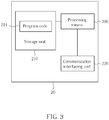
- Fig. 3 illustrates a schematic diagram of an exemplary communication device 20.
- the communication device 20 can be the UE shown in Fig. 1 , but is not limited herein.
- the communication device 20 may include a processing means 200 such as a microprocessor or Application Specific Integrated Circuit (ASIC), a storage unit 210 and a communication interfacing unit 220.
- the storage unit 210 may be any data storage device that can store program code 214, for access by the processing means 200. Examples of the storage unit 210 include but are not limited to a subscriber identity module (SIM), read-only memory (ROM), flash memory, random-access memory (RAM), CD-ROMs, magnetic tape, hard disk, and optical data storage device.
- SIM subscriber identity module
- ROM read-only memory
- flash memory random-access memory
- CD-ROMs magnetic tape
- hard disk hard disk
- optical data storage device optical data storage device.
- the communication interfacing unit 220 is preferably a radio transceiver and can exchange wireless signals with the network according to processing
- Fig. 4 illustrates a schematic diagram of communication protocol layers for LTE-A system.
- the behaviors of some of the protocol layers may be defined in the program code 214 and executed by the processing means 200.
- the protocol layers from top to bottom are a radio resource control (RRC) layer 300, a packet data convergence protocol (PDCP) layer 310, a radio link control (RLC) layer 320, a medium access control (MAC) layer 330 and a physical (PHY) layer 340.
- the MAC layer 330 is responsible for generating a MAC PDU (Protocol Data Unit) including power headroom information when a power headroom reporting (PHR) is triggered.
- MAC PDU Network Data Unit
- the UE may equip one or more radio frequency (RF) modules, RF chains, and/or power amplifiers (PAs) for RF signal transmission.
- RF radio frequency
- PAs power amplifiers
- Each RF module or PA may support one or more than one uplink component carriers. Therefore, power limitation of the RF module and/or PA shall be taken into consideration in LTE-A system. Otherwise, it is difficult to allocate power resource for each component carrier.
- the power limitation may be provided by a manufacturer of the UE or an antenna producer, and may be varied with different manufacturers or producers.
- the minimum required power limitation may be defined in the technical specification, and UEs should be manufactured to meet at least the minimum requirements.
- the power limitation of a PA may be the same as the UE maximum Output power (e.g., 23 dBm or 25dBm).
- the power limitation may be adjusted by a dedicated signalling or broadcast signalling transmitted from the network (e.g. an eNB).
- Fig. 5 illustrates a flowchart of an exemplary process 50.
- the process 50 is utilized in a UE configured with a plurality of uplink component carriers and/or parallel PUCCH and PUSCH transmission, for a maximum output power reporting.
- the process 50 can be compiled into the program code 214 and includes the following steps:
- the UE first determines whether to start or stop the maximum output power reporting, and reports the maximum output power information when the maximum output power reporting is triggered and is started. Otherwise, the UE does not automatically report the maximum output power for the uplink component carriers. Based on the process, the UE does know how to perform the maximum output power reporting for an uplink component carrier.
- the UE may determine to start or stop the maximum output power reporting for the uplink component carriers (e.g. one or all activated uplink component carriers) based on an estimated transmission power, downlink and/or uplink channel quality, the number of configured and/or activated downlink and/or uplink component carriers, mapping information between uplink component carrier and corresponding PA, RF and/or antenna configuration, UL resource assignment, support of parallel PUCCH and PUSCH transmission, previous power headroom report, previous maximum output power report, network (e.g. eNB) and/or UE capability, uplink MIMO enabled and/or configured, timer based solution, or explicit signalling.
- the uplink component carriers e.g. one or all activated uplink component carriers
- the maximum output power reporting may be started when (the sum of) estimated transmission power of corresponding uplink component carriers is going to or may exceed the maximum output power value, UE and/or PA power limitation.
- the maximum output power reporting may be started when downlink and/or uplink channel quality is (bad or) worst than a threshold.
- the threshold value may be provided by the network in advance.
- the maximum output power reporting may be started if there is more than one uplink SCells configured or activated to the UE.
- the maximum output power reporting may be started if there is more than one configured and/or activated uplink component carriers mapped to a PA. Note that, one maximum output power reporting of an uplink component carrier may be started for all uplink component carriers mapped to this PA.
- the UE may provide the UE capability information (e.g., RF Tx architecture, the number of PAs, etc) to the network.
- the mapping information between the uplink component carriers and PA may be provided (e.g., in RRCConnectionReconfiguration and/or RRCConnectionReconfigurationComplete message).
- the maximum output power reporting for a component carrier may be started if there is UL resource (e.g., PUCCH or PUSCH resource) assigned for the component carrier for the TTI.
- the maximum output power reporting may be started if parallel PUCCH and PUSCH transmission is enabled or configured.
- the maximum output power reporting may be started if a negative power headroom value is reported.
- the maximum output power reporting may be started if the power headroom report includes an indicator to inform the network that (the sum of) estimated transmission power of corresponding uplink component carriers may exceed the maximum output power, UE and/or PA limitation.
- the maximum output power reporting may be started/stopped based on the previous maximum output power report and power headroom report.
- the maximum output power reporting may be started/stopped based on whether the uplink MIMO is enabled and/or configured, and/or based on whether higher modulation and coding scheme (e.g., 16QAM, 64QAM, etc) are applied.
- the network may configure UE a timer. When the maximum output power reporting is started, the timer is started, whereas when the timer expires, the maximum output power reporting is stopped.
- the maximum output power reporting may be started if an explicit signalling, indicating the need of the maximum output power report, is received from the network.
- the UE may send a message to notify the network.
- the network may send a message to notify the UE.
- This notification message may be a PHY, MAC, or RRC message.
- the message may be used to notify the start or stop of the maximum output power reporting for all activated uplink component carriers within the UE.
- the message may be used to notify the start or stop of the maximum output power reporting for some activated uplink component carriers.
- the message may include a bitmap.
- a bit in the bitmap is set to "1" to indicate the maximum output power of the corresponding uplink component carrier is reported or should be reported.
- Another bit in the bitmap is set to "0" to indicate the maximum output power of the corresponding uplink component carrier is not reported or should be stopped.
- the maximum output power reporting may be triggered when the power headroom reporting is triggered, when an uplink component carrier corresponding to a SCell is activated, when a timer configured by the network expires (and once the maximum output power is reported, the timer is restarted), when receiving a explicit signalling from the network for triggering the maximum output power reporting, when receiving an UL grant assignment for the component carrier, when downlink and/or uplink channel quality becomes worse than a threshold, when parallel PUCCH and PUSCH transmission is enabled and/or configured, when uplink MIMO is configured and/or enabled, when uplink transmission power is scaling, when the estimated transmission power for an uplink component carrier exceeds the corresponding maximum output power, or when (the sum of) estimated transmission power of corresponding uplink component carriers exceeds the UE and/or PA limitation.
- the UE may report the maximum output power with a difference value (i.e. a delta value), may only report one maximum output power value for two or more component carriers, which have the same or similar maximum output power value, or may report the maximum output power value and a power headroom report in the same message.
- a difference value i.e. a delta value
- the UE may use the same format or different formats for each maximum output power reporting. If the UE use different formats, such as a long format and a short format, the long format may be used for maximum output power value reporting, and the short format may be used for the difference value. In this situation, a logic channel identity (LCID) in a MAC subheader may be used to indicate that the long format or the short format is adopted.
- LCID logic channel identity
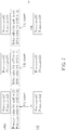
- Figs. 6-11 illustrates a schematic diagram of a single format used in a maximum output power report.
- the difference value (as Delta value in Fig. 6 ) may be based on the previous maximum output power value for the same uplink component carrier. Assume the first maximum output power report indicates the maximum output power value is 23 dBm, which can be a value configured by the network or a pre-defined value.
- the current maximum output power value P CMAX,CC#1 for a first uplink component carrier CC#1 is 21 dBm
- maximum output power value P CMAX,CC#2 for a second uplink component carrier CC#2 is 22 dBm.
- the UE reports that Delta value for the first uplink component carrier CC#1 is "-2" and Delta value for the second uplink component carrier CC#2 is "-1".
- the UE reports that Delta value for the first uplink component carrier CC#1 is "+1", and Delta value for the second uplink component carrier CC#2 is "-2".
- Fig. 7 illustrates a schematic diagram of multiple formats used in a maximum output power report.
- more than one format e.g. the long and short format
- Fig. 8 illustrates a schematic diagram of a maximum output power report format according to a first embodiment.
- the Delta value may be based on maximum output power value of a PCell or UL PCC in Fig. 2 .
- the uplink component carrier CC#1 is the UL PCC.
- Fig. 9 illustrates a schematic diagram of a maximum output power report format according to a second embodiment.
- the Delta value is based on a UE maximum output power P powerclass and a maximum allowed UE output power P EMAX signalled by higher layers.
- the UE reports that Delta value for the first uplink component carrier CC#1 is "0" and Delta value for the second uplink component carrier CC#2 is "-1".
- the network reconfigures the P EMAX , the UE calculates the new P CMAX_H , and then reports the Delta value according to the new P CMAX_H .
- the detailed description or definition of the abovementioned parameters can be referred to 3GPP TS 36.101 specification.
- Fig. 10 illustrates a schematic diagram of a maximum output power report format according to a third embodiment.
- Fig. 11 illustrates a schematic diagram of a maximum output power report format according to a fourth embodiment.
- the Delta value is based on the pre-defined value. This value may be defined in the specification for LTE-A system or stored in the UE. Assume the pre-defined value is 23.
- the current maximum output power value P CMAX,CC#1 for a first uplink component carrier CC#1 is 21 dBm
- maximum output power value P CMAX,CC#2 for a second uplink component carrier CC#2 is 22 dBm.
- the UE reports the Delta value for the first uplink component carrier CC#1 is "-2", and Delta value for the second uplink component carrier CC#2 is "-1".
- the UE may report one maximum output power value for more than one uplink component carriers.
- these uplink component carriers may have the same (or similar) maximum output power value.
- these uplink component carriers may be mapped the same PA.
- the UE may choose the same maximum output power value for these uplink component carriers for which the maximum output power value is in-between their limitations.
- the UE may choose the same maximum output power value for the uplink component carriers which share the same PA. Therefore, the UE reports one maximum output power value for the uplink component carriers which share the same PA.
- the UE may inform the network the mapping of the uplink component carriers and PA by UE capability negotiation message, or by RRC message/ MAC control element.
- the UE may inform the network which uplink component carriers share the same maximum output power value by RRC message/ MAC control element.
- An indicator in the report message may indicate which component carrier (or cell) refers to this maximum output power value or this Delta value.
- the indicator may be a bitmap.
- the bitmap is used to indicate which component carrier this maximum output power value is applied to.
- a bit in the bitmap is set to "1" to indicate that the corresponding cell may apply this maximum output power value.
- a bit in the bitmap is set to "0" to indicate that the corresponding cell may not apply this maximum output power value.
- the bitmap is used to indicate which component carrier this Delta value is applied to.
- the UE may send power headroom report in one message (e.g. MAC CE) and/or send maximum output power report in another message (e.g. MAC CE).
- These two MAC CEs may be transmitted at the same time (e.g. subframe). Or, these two MAC CEs may be transmitted on the same uplink component carrier and/or on different uplink component carriers.
- two or more LCIDs may be used for maximum output power report and power headroom report. For example, one LCID is used for the power headroom report, and another LCID is used for the maximum output power report.
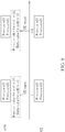
- Fig. 12 illustrates a flowchart of an exemplary process 120.
- the process 120 is utilized in a network (e.g. eNB) for handling power reporting.
- the process 120 can be compiled into the program code 214 and includes the following steps:
- the network controls uplink transmission power and/or manage uplink resource (e.g. resource block (RB) assignment, modulation and coding scheme (MCS)) based on not only the power headroom report but also the maximum output power report.
- uplink resource e.g. resource block (RB) assignment, modulation and coding scheme (MCS)
- MCS modulation and coding scheme
- the network may estimate the UE's transmission power on a corresponding uplink component carrier by (maximum output power value - the reported power headroom value). Therefore, the network may not allocate transmission power on an uplink component carrier exceeds the corresponding maximum output power value/PA power limitation, and/or UE power limitation.
- the abovementioned steps of the processes including suggested steps can be realized by means that could be hardware, firmware known as a combination of a hardware device and computer instructions and data that reside as read-only software on the hardware device, or an electronic system.
- hardware can include analog, digital and mixed circuits known as microcircuit, microchip, or silicon chip.
- the electronic system can include system on chip (SOC), system in package (Sip), computer on module (COM), and the communication device 20.
- SOC system on chip
- Sip system in package
- COM computer on module
- the present invention provides methods and apparatus for power reporting (e.g. the maximum output power for an uplink component carrier) in multiple uplink component carrier system, so that the network can perform power control and resource management well.
- power reporting e.g. the maximum output power for an uplink component carrier
Landscapes
- Engineering & Computer Science (AREA)
- Computer Networks & Wireless Communication (AREA)
- Signal Processing (AREA)
- Mobile Radio Communication Systems (AREA)
Claims (10)
- Verfahren zum Auswerten einer Leistung für ein Mobilgerät, das mit mehreren Uplink-Komponententräger und parallelen PUCCH- und PUSCH-Übertragung ausgestattet ist, in einem Drahtlos-Kommunikationssystem, wobei das Verfahren umfasst:Konfiguriert sein einer maximalen Ausgangsleistung für mindestens einen Uplink-Komponenten-Träger;Bestimmten, ob eine Auswertung einer maximalen Ausgangsleistung für den mindestens einen Uplink-Komponenten-Träger gemäß der mit dem Mobilgerät assoziierten Eigenschaft gestartet werden soll; andBerichten der maximalen Ausgangsleistung für den mindestens einen Uplink- Komponenten-Träger an das Netzwerk, wenn das Auswerten der maximalen Ausgangsleistung ausgelöst und das Auswerten der maximalen Ausgangsleistung gestartet wird;worin die mit dem Mobilgerät assoziierte Eigenschaft umfasst, eine Anzahl an konfigurierten und aktivierten Downlink- und Uplink-Komponententrägern, eine Funkfrequenz und Antennen-Konfiguration, einen Träger einer parallelen PUCCH- und PUSCH-Übertragung, eine vorhergehende Leistungsreserven-Auswertung, eine vorhergehende maximale Ausgangsleistungs-Auswertung, eine Mobilgerät-Fähigkeit, eine Uplink-MIMO aktiviert und konfiguriert, oder ein explizites Signal.
- Verfahren nach Anspruch 1, weiter umfassend:
beim Bestimmen, die maximale Ausgangsleistungs-Auswertung für den mindestens einen Uplink-Komponenten-Träger zu starten, Übertragen einer Nachricht, um das Netzwerk zu informieren. - Verfahren nach Anspruch 2, dadurch gekennzeichnet, dass die Nachricht den Beginn des Auswertung der maximalen Ausgangsleistung für alle oder einige Uplink-Komponententräger der mehreren Komponententräger anzeigt; oder dass die Nachricht eine Bitmap zum Anzeigen des Starts des Berichts der maximalen Ausgangsleistung für einen entsprechenden Komponenten-Träger umfasst.
- Verfahren nach Anspruch 1, dadurch gekennzeichnet, dass die Auswertung der maximalen Ausgangsleistung ausgelöst wird, je nachdem ob ein Leistungsreserve-Auswertung (PHR) ausgelöst wird, ob ein sekundärer Uplink-Komponenten-Träger aktiviert und/oder konfiguriert wird, ob ein Zeitgeber ausläuft, der durch das Netzwerk konfiguriert ist, aufgrund eines expliziten Signals, das von dem Netzwerk empfangen wurde, um die Auswertung der maximalen Ausgangsleistung auszulösen, einer UL Genehmigungs-Zuordnung, einem Zustand einer Downlink- und/oder Uplink-Kanal-Qualität, einer parallelen PUCCH und PUSCH Übertragung aktiviert und/oder konfiguriert, einer Uplink-MIMO konfiguriert und/oder aktiviert, einem Scaling einer Uplink-Übertragungsleistung, ob eine geschätzte Übertragungsleistung für einen Uplink-Komponenten-Träger die maximale Ausgangsleistung des Uplink-Komponenten-Trägers übersteigt, oder ob die geschätzte Übertragungsleistung für mindestens einen Uplink-Komponenten-Träger eine Leistungsbeschränkung des Mobilgeräts und/oder eines Leistungssteigerers, der für den mindestens einen Uplink-Komponenten-Träger konfiguriert ist, übersteigt.
- Verfahren nach Anspruch 1, dadurch gekennzeichnet, dass Berichten der maximalen Ausgangsleistung für den mindestens einen Uplink-Komponenten-Träger an das Netzwerk, wenn das Auswerten der maximalen Ausgangsleistung ausgelöst wird, und das Auswerten der maximalen Ausgangsleistung gestartet wird, umfasst:Berichten des maximalen Ausgangsleistungs-Wertes für den mindestens einen Uplink-Komponenten-Träger direkt, wenn das Auswerten der maximalen Ausgangsleistung ausgelöst und das Auswerten der maximalen Ausgangsleistung gestartet wird; oderBerichten des maximalen Ausgangsleistungs-Wertes für den mindestens einen Uplink-Komponenten-Träger mit einem Unterschieds-Wert, wenn das Auswerten der maximalen Ausgangsleistung ausgelöst und das Auswerten der maximalen Ausgangsleistung gestartet wird; oderBerichten eines maximalen Ausgangsleistungs-Wertes für den mindestens einen Uplink-Komponenten-Träger, wenn das Auswerten der maximalen Ausgangsleistung ausgelöst und das Auswerten der maximalen Ausgangsleistung gestartet wird.
- Verfahren nach Anspruch 5, dadurch gekennzeichnet, dass Berichten des maximalen Ausgangsleistung-Werts für den mindestens einen Uplink-Komponenten-Träger mit einem Unterschieds-Wert, wenn das Auswerten der maximalen Ausgangsleistung ausgelöst und das Auswerten der maximalen Ausgangsleistung gestartet wird, umfasst:Berichten des maximalen Ausgangsleistung-Werts für den mindestens einen Uplink-Komponenten-Träger mit einem Unterschieds-Wert zwischen einem vorhergehenden maximalen Ausgangsleistungs-Wert und dem maximalen Ausgangsleistungs-Wert auf dem gleichen Komponenten-Träger, wenn das Auswerten der maximalen Ausgangsleistung ausgelöst und das Auswerten der maximalen Ausgangsleistung gestartet wird; oderBerichten des maximalen Ausgangsleistung-Werts für den mindestens einen Uplink-Komponenten-Träger mit einem Unterschieds-Wert zwischen einem maximalen Ausgangsleistungs-Wert eines primären Uplink-Komponenten-Träger und dem maximalen Ausgangsleistungs-Wert, wenn das Auswerten der maximalen Ausgangsleistung ausgelöst und das Auswerten der maximalen Ausgangsleistung gestartet wird; oderBerichten des maximalen Ausgangsleistung-Werts für den mindestens einen Uplink-Komponenten-Träger mit einem Unterschieds-Wert zwischen einem Wert einer maximalen Ausgangsleistung des Mobilgerät oder einer maximal erlaubten Ausgangsleistung des Mobilgeräts, und dem maximalen Ausgangsleistungs-Wert, wenn das Auswerten der maximalen Ausgangsleistung ausgelöst und das Auswerten der maximalen Ausgangsleistung gestartet wird; oderBerichten des maximalen Ausgangsleistung-Werts für den mindestens einen Uplink-Komponenten-Träger mit einem Unterschieds-Wert zwischen einem Referenz-Wert, der von dem Netzwerk konfiguriert ist, und dem maximalen Ausgangsleistungs-Wert, wenn das Auswerten der maximalen Ausgangsleistung ausgelöst und das Auswerten der maximalen Ausgangsleistung gestartet wird; oderBerichten des maximalen Ausgangsleistung-Werts für den mindestens einen Uplink-Komponenten-Träger mit einem Unterschieds-Wert zwischen einem bestimmten Wert, der in dem Mobilgerät gespeichert ist, und dem maximalen Ausgangsleistungs-Wert, wenn das Auswerten der maximalen Ausgangsleistung ausgelöst und das Auswerten der maximalen Ausgangsleistung gestartet wird.
- Verfahren nach Anspruch 5, dadurch gekennzeichnet, dass Berichten eines maximalen Ausgangsleistungs-Werts für den mindestens einen Uplink-Komponenten-Träger, wenn das Auswerten der maximalen Ausgangsleistung ausgelöst und das Auswerten der maximalen Ausgangsleistung gestartet wird umfasst:Berichten eines maximalen Ausgangsleistungs-Werts für den mindestens einen Uplink-Komponenten-Träger mit der gleichen oder vergleichbaren maximalen Ausgangsleistung wenn das Auswerten der maximalen Ausgangsleistung ausgelöst und das Auswerten der maximalen Ausgangsleistung gestartet wird; oderBerichten eines maximalen Ausgangsleistungs-Werts für den mindestens einen Uplink-Komponenten-Träger, wenn das Auswerten der maximalen Ausgangsleistung ausgelöst und das Auswerten der maximalen Ausgangsleistung gestartet wird, worin der maximale Ausgangsleistungs-Wert zwischen Beschränkungen des mindestens einen Uplink-Komponenten-Trägers ist; oderBerichten eines maximalen Ausgangsleistungs-Werts für den mindestens einen Uplink-Komponenten-Träger, Teilen des gleichen Leistungsverstärkers, wenn das Auswerten der maximalen Ausgangsleistung ausgelöst und das Auswerten der maximalen Ausgangsleistung gestartet wird.
- Verfahren zur Handhabung zum Berichten einer Leistung an ein Netzwerk in einem Drahtlos-Kommunikationssystem, dadurch gekennzeichnet, dass das Verfahren umfasst:Konfigurieren mehrerer Uplink-Komponententräger und paralleler PUCCH- und PUSCH- Übertragungen an ein Mobilgerät des Drahtlos-Kommunikationssystems;Bereitstellen von Informationen, die mit einer maximalen Ausgangsleistungs-Konfiguration für mindestens einen Uplink-Komponenten-Träger assoziiert sind; undBestimmen, ob eine Auswertung einer maximalen Ausgangsleistung für den mindestens einen Uplink-Komponenten-Träger in dem Mobilgerät gemäß einer mit dem Mobilgerät assoziierten Eigenschaft gestartet werden soll;worin die mit dem Mobilgerät assoziierte Eigenschaft umfasst, eine Anzahl an konfigurierten und aktivierten Downlink- und/oder Uplink-Komponententräger, eine Funkfrequenz und Antennen-Konfiguration, einen Träger einer parallelen PUCCH- und PUSCH-Übertragung, eine vorhergehende Leistungsreserve-Auswertung, eine vorhergehende maximalen Ausgangsleistungs-Auswertung, eine Mobilgerät-Fähigkeit, eine Uplink-MIMO aktiviert und konfiguriert, oder ein explizites Signal.
- Verfahren nach Anspruch 8, weiter umfassend:
beim Bestimmen, die maximale Ausgangsleistungs-Auswertung für den mindestens einen Uplink-Komponenten-Träger in dem Mobilgerät zu starten, Übertragen einer Nachricht, um das Mobilgerät zu benachrichtigen. - Verfahren nach Anspruch 9, dadurch gekennzeichnet, dass die Nachricht den Start des Auswertens der maximalen Ausgangsleistung für alle oder einige Uplink-Komponententräger der mehreren Komponententräger anzeigt; oder dass die Nachricht eine Bitmap umfasst, um den Start der Auswertung der maximalen Ausgangsleistung für einen entsprechenden Komponenten-Träger anzuzeigen.
Applications Claiming Priority (2)
| Application Number | Priority Date | Filing Date | Title |
|---|---|---|---|
| US41119210P | 2010-11-08 | 2010-11-08 | |
| US13/280,347 US8737333B2 (en) | 2010-11-08 | 2011-10-25 | Method of power reporting and communication device thereof |
Publications (3)
| Publication Number | Publication Date |
|---|---|
| EP2451225A2 EP2451225A2 (de) | 2012-05-09 |
| EP2451225A3 EP2451225A3 (de) | 2014-01-01 |
| EP2451225B1 true EP2451225B1 (de) | 2019-12-25 |
Family
ID=44999702
Family Applications (1)
| Application Number | Title | Priority Date | Filing Date |
|---|---|---|---|
| EP11187596.9A Active EP2451225B1 (de) | 2010-11-08 | 2011-11-03 | Leistungsbenachrichtigungsverfahren in einem drahtlosen Kommunikationssystem |
Country Status (8)
| Country | Link |
|---|---|
| US (1) | US8737333B2 (de) |
| EP (1) | EP2451225B1 (de) |
| JP (1) | JP2012105268A (de) |
| KR (1) | KR101318314B1 (de) |
| CN (1) | CN102469565B (de) |
| AU (1) | AU2011247852A1 (de) |
| RU (1) | RU2501188C2 (de) |
| TW (1) | TWI466570B (de) |
Families Citing this family (29)
| Publication number | Priority date | Publication date | Assignee | Title |
|---|---|---|---|---|
| US20140036879A1 (en) * | 2011-02-13 | 2014-02-06 | Renesas Mobile Corporation | Method and Apparatus for Configuring Transmission of a Power Headroom Report in Carrier Aggregation Systems |
| US20130051261A1 (en) * | 2011-06-21 | 2013-02-28 | Telefonaktiebolaget Lm Ericsson (Publ) | Selecting Uplink Multi-Antenna Transmission to Enhance Coverage |
| JP5483621B2 (ja) * | 2011-08-12 | 2014-05-07 | 株式会社Nttドコモ | 移動通信方法 |
| KR102092579B1 (ko) | 2011-08-22 | 2020-03-24 | 삼성전자 주식회사 | 이동통신 시스템에서 복수 개의 주파수 밴드 지원 방법 및 장치 |
| CN102523627B (zh) * | 2011-12-08 | 2014-04-02 | 电信科学技术研究院 | 一种数据传输方法及装置 |
| EP3934358B1 (de) | 2011-12-09 | 2024-03-27 | Telefonaktiebolaget LM Ericsson (publ) | Planung von verzogerungsanfalligem verkehr |
| JP6324319B2 (ja) * | 2012-01-09 | 2018-05-16 | サムスン エレクトロニクス カンパニー リミテッド | ロギング方法及び装置 |
| EP2809102B1 (de) | 2012-01-27 | 2023-01-25 | Samsung Electronics Co., Ltd. | Verfahren und vorrichtung zur effizienten zugangskontrolle für systemlastanpassung in mobilen kommunikationssystemen |
| US9414409B2 (en) | 2012-02-06 | 2016-08-09 | Samsung Electronics Co., Ltd. | Method and apparatus for transmitting/receiving data on multiple carriers in mobile communication system |
| WO2013118978A1 (ko) | 2012-02-06 | 2013-08-15 | 삼성전자 주식회사 | 무선 통신 시스템에서 small data를 효율적으로 전송하는 방법 및 장치 |
| US9806873B2 (en) | 2012-05-09 | 2017-10-31 | Samsung Electronics Co., Ltd. | Method and apparatus for controlling discontinuous reception in mobile communication system |
| EP2854443B1 (de) | 2012-05-21 | 2019-10-30 | Samsung Electronics Co., Ltd. | Verfahren und vorrichtung zum senden und empfangen von daten in einem mobilkommunikationssystem |
| US8942754B2 (en) * | 2012-08-07 | 2015-01-27 | Sharp Laboratories Of America, Inc. | Devices for allocating power for uplink transmission |
| CN104956748B (zh) * | 2013-01-25 | 2019-01-22 | 日本电气株式会社 | 移动站、基站以及发送和接收功率余量报告的方法 |
| US9282523B2 (en) * | 2013-04-26 | 2016-03-08 | Mediatek Inc. | Maximum output power configuration with UE preference in carrier aggregation |
| CN104144447B (zh) * | 2013-05-08 | 2018-06-26 | 中国移动通信集团公司 | 一种信息传输方法和设备 |
| JP6668242B2 (ja) | 2013-09-04 | 2020-03-18 | エルジー エレクトロニクス インコーポレイティド | 無線通信システムにおける上りリンク電力を制御する方法及び装置 |
| EP2854460B1 (de) * | 2013-09-27 | 2017-04-05 | Sun Patent Trust | Leistungssteuerung und Leistungsreservemitteilung für duale Konnektivität |
| US10278139B2 (en) | 2013-12-20 | 2019-04-30 | Lg Electronics Inc. | Method for power headroom reporting and device therefor |
| US9699690B2 (en) * | 2014-03-20 | 2017-07-04 | Telefonaktiebolaget Lm Ericsson (Publ) | Node and method for carrier aggregation compatibility reporting of a wireless device |
| US9585106B2 (en) * | 2014-03-27 | 2017-02-28 | Taiwan Semiconductor Manufacturing Company, Ltd. | Network-assisted channel selection and power control for mobile devices |
| CN114221742B (zh) * | 2015-07-28 | 2024-03-08 | 松下电器(美国)知识产权公司 | 通信装置、通信方法及集成电路 |
| PL3852437T3 (pl) * | 2016-05-13 | 2024-05-27 | Telefonaktiebolaget Lm Ericsson (Publ) | Sposób rekomendowania szybkości przesyłania danych w systemie komunikacji bezprzewodowej |
| EP3469723A1 (de) * | 2016-06-08 | 2019-04-17 | Huawei Technologies Co., Ltd. | Vorrichtung und verfahren für drahtloskommunikationssystem |
| US10356724B2 (en) | 2016-07-29 | 2019-07-16 | Acer Incorporated | Device handling power control for time intervals based on power level limit |
| US10728860B2 (en) | 2016-07-29 | 2020-07-28 | Acer Incorporated | Device and method of handling power headroom report for multiple time intervals |
| US10470140B2 (en) * | 2017-05-04 | 2019-11-05 | Qualcomm Incorporated | Power headroom report for uplink split bearer communications |
| WO2022265544A1 (en) * | 2021-06-17 | 2022-12-22 | Telefonaktiebolaget Lm Ericsson (Publ) | Limiting interference in a wireless point-to-point or point-to-multipoint network |
| KR20250123456A (ko) * | 2024-02-08 | 2025-08-18 | 삼성전자주식회사 | 무선 통신 시스템에서 다중 안테나 전송 시 상향링크 전송 출력 제어 방법 및 장치 |
Family Cites Families (22)
| Publication number | Priority date | Publication date | Assignee | Title |
|---|---|---|---|---|
| US8274952B2 (en) | 2006-10-10 | 2012-09-25 | Alcatel Lucent | Transmission power management |
| EP2171871B1 (de) | 2007-06-20 | 2019-04-17 | Cellular Communications Equipment Llc | Leistungsreserven-meldeverfahren |
| US9084201B2 (en) * | 2008-01-25 | 2015-07-14 | Qualcomm Incorporated | Power headroom management in wireless communication systems |
| RU2353043C1 (ru) | 2008-03-11 | 2009-04-20 | Государственное Образовательное Учреждение Высшего Профессионального Образования "Общевойсковая Академия Вооруженных Сил Российской Федерации" (Оа Вс Рф) | Устройство для контроля состояния фаз промышленной сети |
| AU2009228928B2 (en) | 2008-03-26 | 2014-04-03 | Cellular Communications Equipment Llc | Extension of power headroom reporting and trigger conditions |
| US8654701B2 (en) * | 2008-11-13 | 2014-02-18 | Telefonaktiebolaget Lm Ericsson (Publ) | Creation and signalling of UE lists to support frequency selective repeater operation |
| KR20150023886A (ko) | 2008-12-03 | 2015-03-05 | 인터디지탈 패튼 홀딩스, 인크 | 캐리어 집적에 대한 업링크 파워 헤드룸 보고 |
| US8379581B2 (en) | 2008-12-08 | 2013-02-19 | Sharp Kabushiki Kaisha | Systems and methods for uplink power control |
| WO2010082888A1 (en) * | 2009-01-14 | 2010-07-22 | Telefonaktiebolaget L M Ericsson (Publ) | Method and arrangement in a wireless communication system |
| TWI439160B (zh) * | 2009-03-16 | 2014-05-21 | Htc Corp | 於載波聚合模式中處理上鏈路資訊的方法及相關裝置 |
| TWI413431B (zh) | 2009-03-23 | 2013-10-21 | Innovative Sonic Corp | 進行功率餘量回報的方法及通訊裝置 |
| EP2244515A1 (de) | 2009-04-23 | 2010-10-27 | Panasonic Corporation | Logisches Kanalpriorisierungsverfahren zur Erzeugung von mehrfachen Uplink-Transportblöcken |
| CN102577541B (zh) * | 2009-10-01 | 2015-07-15 | 交互数字专利控股公司 | 功率控制方法和设备 |
| US8315661B2 (en) * | 2009-12-31 | 2012-11-20 | Cellco Partnership | Enhanced power headroom reporting |
| CN101778416B (zh) * | 2010-02-10 | 2015-05-20 | 中兴通讯股份有限公司 | 功率上升空间的测量和报告方法及终端 |
| EP2360866A1 (de) | 2010-02-12 | 2011-08-24 | Panasonic Corporation | Aktivierung bzw. Deaktivierung von Frequenzkomponenten mithilfe von Ressourcenzuweisungen |
| US8798663B2 (en) * | 2010-10-01 | 2014-08-05 | Acer Incorporated | Method of performing power headroom reporting and communication device thereof |
| CN102457351B (zh) * | 2010-10-29 | 2017-02-15 | 广州飞曙电子科技有限公司 | 一种获取ue载波实际功率空间的方法及系统 |
| US9055544B2 (en) * | 2010-11-02 | 2015-06-09 | Alcatel Lucent | Methods of setting maximum output power for user equipment and reporting power headroom, and the user equipment |
| WO2012060612A2 (en) * | 2010-11-03 | 2012-05-10 | Pantech Co., Ltd. | Apparatus and method of transmitting power information regarding component carrier in multi-component carrier system |
| KR20120048390A (ko) | 2010-11-05 | 2012-05-15 | 주식회사 팬택 | 다중 요소 반송파 시스템에서 요소 반송파에 대한 전력정보 전송장치 및 방법 |
| JP5764663B2 (ja) | 2010-11-05 | 2015-08-19 | テレフオンアクチーボラゲット エル エム エリクソン(パブル) | 電力ヘッドルーム制御エレメント、ユーザ装置からの電力情報の伝達方法、受信した電力情報を処理する方法、及び対応するユーザ装置並びに基地局 |
-
2011
- 2011-10-25 US US13/280,347 patent/US8737333B2/en active Active
- 2011-11-03 EP EP11187596.9A patent/EP2451225B1/de active Active
- 2011-11-04 JP JP2011242203A patent/JP2012105268A/ja active Pending
- 2011-11-07 RU RU2011145013/07A patent/RU2501188C2/ru active
- 2011-11-08 TW TW100140795A patent/TWI466570B/zh active
- 2011-11-08 KR KR1020110115976A patent/KR101318314B1/ko active Active
- 2011-11-08 AU AU2011247852A patent/AU2011247852A1/en not_active Abandoned
- 2011-11-08 CN CN201110350369.1A patent/CN102469565B/zh active Active
Non-Patent Citations (1)
| Title |
|---|
| None * |
Also Published As
| Publication number | Publication date |
|---|---|
| KR20120049157A (ko) | 2012-05-16 |
| RU2501188C2 (ru) | 2013-12-10 |
| US8737333B2 (en) | 2014-05-27 |
| EP2451225A3 (de) | 2014-01-01 |
| KR101318314B1 (ko) | 2013-10-15 |
| EP2451225A2 (de) | 2012-05-09 |
| JP2012105268A (ja) | 2012-05-31 |
| RU2011145013A (ru) | 2013-05-20 |
| TW201234901A (en) | 2012-08-16 |
| CN102469565B (zh) | 2015-02-11 |
| CN102469565A (zh) | 2012-05-23 |
| AU2011247852A1 (en) | 2012-05-24 |
| TWI466570B (zh) | 2014-12-21 |
| US20120113915A1 (en) | 2012-05-10 |
Similar Documents
| Publication | Publication Date | Title |
|---|---|---|
| EP2451225B1 (de) | Leistungsbenachrichtigungsverfahren in einem drahtlosen Kommunikationssystem | |
| US8798663B2 (en) | Method of performing power headroom reporting and communication device thereof | |
| US9854543B2 (en) | Carrier aggregation with power headroom report | |
| US9629097B2 (en) | Method and apparatus for configuring uplink transmission power based on time alignment groups | |
| JP5465359B2 (ja) | 無線通信システムにおけるパワーヘッドルーム報告方法及び装置 | |
| CN103053195B (zh) | 在无线通信系统中报告测量结果的设备和方法 | |
| CN103270799B (zh) | 用于允许在电信系统中的phr中功率回退指示的方法和设备 | |
| CN103201973B (zh) | 传输功率报告方法和装置 | |
| EP3086608A1 (de) | Verfahren und vorrichtung für energiereservenberichte während eines mehrträgerbetriebs | |
| EP2400802A1 (de) | Verfahren zur Handhabung der Übertragungsleistungssteuerung und Steuerzeicheneingabe sowie zugehörige Kommunikationsvorrichtung | |
| KR20110133444A (ko) | 업링크 전송 수행 방법 및 관련 통신 장치 | |
| EP2418895B1 (de) | Verfahren zur Abwicklung der Power-Headroom-Berichterstattung zur Uplink-Carrier-Aggregation und Kommunikationsendgerät dafür | |
| CN102595613A (zh) | 载波聚合场景下上报小区特定的最大功率的方法及装置 | |
| HK1229123A1 (en) | Methods and apparatuses for enabling power back-off indication in phr in a telecommunications system | |
| BRPI1107070A2 (pt) | método para relatar potência e dispositivo de comunicação do mesmo | |
| HK1188895B (en) | Methods and apparatuses for enabling power back-off indication in phr in a telecommunications system | |
| HK1188895A (en) | Methods and apparatuses for enabling power back-off indication in phr in a telecommunications system |
Legal Events
| Date | Code | Title | Description |
|---|---|---|---|
| PUAI | Public reference made under article 153(3) epc to a published international application that has entered the european phase |
Free format text: ORIGINAL CODE: 0009012 |
|
| AK | Designated contracting states |
Kind code of ref document: A2 Designated state(s): AL AT BE BG CH CY CZ DE DK EE ES FI FR GB GR HR HU IE IS IT LI LT LU LV MC MK MT NL NO PL PT RO RS SE SI SK SM TR |
|
| AX | Request for extension of the european patent |
Extension state: BA ME |
|
| PUAL | Search report despatched |
Free format text: ORIGINAL CODE: 0009013 |
|
| AK | Designated contracting states |
Kind code of ref document: A3 Designated state(s): AL AT BE BG CH CY CZ DE DK EE ES FI FR GB GR HR HU IE IS IT LI LT LU LV MC MK MT NL NO PL PT RO RS SE SI SK SM TR |
|
| AX | Request for extension of the european patent |
Extension state: BA ME |
|
| RIC1 | Information provided on ipc code assigned before grant |
Ipc: H04W 52/36 20090101AFI20131128BHEP |
|
| 17P | Request for examination filed |
Effective date: 20140701 |
|
| RBV | Designated contracting states (corrected) |
Designated state(s): AL AT BE BG CH CY CZ DE DK EE ES FI FR GB GR HR HU IE IS IT LI LT LU LV MC MK MT NL NO PL PT RO RS SE SI SK SM TR |
|
| 17Q | First examination report despatched |
Effective date: 20140902 |
|
| STAA | Information on the status of an ep patent application or granted ep patent |
Free format text: STATUS: EXAMINATION IS IN PROGRESS |
|
| GRAP | Despatch of communication of intention to grant a patent |
Free format text: ORIGINAL CODE: EPIDOSNIGR1 |
|
| STAA | Information on the status of an ep patent application or granted ep patent |
Free format text: STATUS: GRANT OF PATENT IS INTENDED |
|
| INTG | Intention to grant announced |
Effective date: 20190613 |
|
| GRAS | Grant fee paid |
Free format text: ORIGINAL CODE: EPIDOSNIGR3 |
|
| GRAA | (expected) grant |
Free format text: ORIGINAL CODE: 0009210 |
|
| STAA | Information on the status of an ep patent application or granted ep patent |
Free format text: STATUS: THE PATENT HAS BEEN GRANTED |
|
| AK | Designated contracting states |
Kind code of ref document: B1 Designated state(s): AL AT BE BG CH CY CZ DE DK EE ES FI FR GB GR HR HU IE IS IT LI LT LU LV MC MK MT NL NO PL PT RO RS SE SI SK SM TR |
|
| REG | Reference to a national code |
Ref country code: GB Ref legal event code: FG4D |
|
| REG | Reference to a national code |
Ref country code: CH Ref legal event code: EP |
|
| REG | Reference to a national code |
Ref country code: DE Ref legal event code: R096 Ref document number: 602011064190 Country of ref document: DE |
|
| REG | Reference to a national code |
Ref country code: AT Ref legal event code: REF Ref document number: 1218550 Country of ref document: AT Kind code of ref document: T Effective date: 20200115 |
|
| REG | Reference to a national code |
Ref country code: IE Ref legal event code: FG4D |
|
| REG | Reference to a national code |
Ref country code: NL Ref legal event code: FP |
|
| PG25 | Lapsed in a contracting state [announced via postgrant information from national office to epo] |
Ref country code: LV Free format text: LAPSE BECAUSE OF FAILURE TO SUBMIT A TRANSLATION OF THE DESCRIPTION OR TO PAY THE FEE WITHIN THE PRESCRIBED TIME-LIMIT Effective date: 20191225 Ref country code: SE Free format text: LAPSE BECAUSE OF FAILURE TO SUBMIT A TRANSLATION OF THE DESCRIPTION OR TO PAY THE FEE WITHIN THE PRESCRIBED TIME-LIMIT Effective date: 20191225 Ref country code: LT Free format text: LAPSE BECAUSE OF FAILURE TO SUBMIT A TRANSLATION OF THE DESCRIPTION OR TO PAY THE FEE WITHIN THE PRESCRIBED TIME-LIMIT Effective date: 20191225 Ref country code: GR Free format text: LAPSE BECAUSE OF FAILURE TO SUBMIT A TRANSLATION OF THE DESCRIPTION OR TO PAY THE FEE WITHIN THE PRESCRIBED TIME-LIMIT Effective date: 20200326 Ref country code: NO Free format text: LAPSE BECAUSE OF FAILURE TO SUBMIT A TRANSLATION OF THE DESCRIPTION OR TO PAY THE FEE WITHIN THE PRESCRIBED TIME-LIMIT Effective date: 20200325 Ref country code: FI Free format text: LAPSE BECAUSE OF FAILURE TO SUBMIT A TRANSLATION OF THE DESCRIPTION OR TO PAY THE FEE WITHIN THE PRESCRIBED TIME-LIMIT Effective date: 20191225 Ref country code: BG Free format text: LAPSE BECAUSE OF FAILURE TO SUBMIT A TRANSLATION OF THE DESCRIPTION OR TO PAY THE FEE WITHIN THE PRESCRIBED TIME-LIMIT Effective date: 20200325 |
|
| REG | Reference to a national code |
Ref country code: LT Ref legal event code: MG4D |
|
| PG25 | Lapsed in a contracting state [announced via postgrant information from national office to epo] |
Ref country code: HR Free format text: LAPSE BECAUSE OF FAILURE TO SUBMIT A TRANSLATION OF THE DESCRIPTION OR TO PAY THE FEE WITHIN THE PRESCRIBED TIME-LIMIT Effective date: 20191225 Ref country code: RS Free format text: LAPSE BECAUSE OF FAILURE TO SUBMIT A TRANSLATION OF THE DESCRIPTION OR TO PAY THE FEE WITHIN THE PRESCRIBED TIME-LIMIT Effective date: 20191225 |
|
| PG25 | Lapsed in a contracting state [announced via postgrant information from national office to epo] |
Ref country code: AL Free format text: LAPSE BECAUSE OF FAILURE TO SUBMIT A TRANSLATION OF THE DESCRIPTION OR TO PAY THE FEE WITHIN THE PRESCRIBED TIME-LIMIT Effective date: 20191225 |
|
| PG25 | Lapsed in a contracting state [announced via postgrant information from national office to epo] |
Ref country code: PT Free format text: LAPSE BECAUSE OF FAILURE TO SUBMIT A TRANSLATION OF THE DESCRIPTION OR TO PAY THE FEE WITHIN THE PRESCRIBED TIME-LIMIT Effective date: 20200520 Ref country code: EE Free format text: LAPSE BECAUSE OF FAILURE TO SUBMIT A TRANSLATION OF THE DESCRIPTION OR TO PAY THE FEE WITHIN THE PRESCRIBED TIME-LIMIT Effective date: 20191225 Ref country code: CZ Free format text: LAPSE BECAUSE OF FAILURE TO SUBMIT A TRANSLATION OF THE DESCRIPTION OR TO PAY THE FEE WITHIN THE PRESCRIBED TIME-LIMIT Effective date: 20191225 Ref country code: RO Free format text: LAPSE BECAUSE OF FAILURE TO SUBMIT A TRANSLATION OF THE DESCRIPTION OR TO PAY THE FEE WITHIN THE PRESCRIBED TIME-LIMIT Effective date: 20191225 |
|
| PG25 | Lapsed in a contracting state [announced via postgrant information from national office to epo] |
Ref country code: SM Free format text: LAPSE BECAUSE OF FAILURE TO SUBMIT A TRANSLATION OF THE DESCRIPTION OR TO PAY THE FEE WITHIN THE PRESCRIBED TIME-LIMIT Effective date: 20191225 Ref country code: SK Free format text: LAPSE BECAUSE OF FAILURE TO SUBMIT A TRANSLATION OF THE DESCRIPTION OR TO PAY THE FEE WITHIN THE PRESCRIBED TIME-LIMIT Effective date: 20191225 Ref country code: IS Free format text: LAPSE BECAUSE OF FAILURE TO SUBMIT A TRANSLATION OF THE DESCRIPTION OR TO PAY THE FEE WITHIN THE PRESCRIBED TIME-LIMIT Effective date: 20200425 |
|
| REG | Reference to a national code |
Ref country code: DE Ref legal event code: R097 Ref document number: 602011064190 Country of ref document: DE |
|
| PG25 | Lapsed in a contracting state [announced via postgrant information from national office to epo] |
Ref country code: DK Free format text: LAPSE BECAUSE OF FAILURE TO SUBMIT A TRANSLATION OF THE DESCRIPTION OR TO PAY THE FEE WITHIN THE PRESCRIBED TIME-LIMIT Effective date: 20191225 Ref country code: ES Free format text: LAPSE BECAUSE OF FAILURE TO SUBMIT A TRANSLATION OF THE DESCRIPTION OR TO PAY THE FEE WITHIN THE PRESCRIBED TIME-LIMIT Effective date: 20191225 |
|
| PLBE | No opposition filed within time limit |
Free format text: ORIGINAL CODE: 0009261 |
|
| STAA | Information on the status of an ep patent application or granted ep patent |
Free format text: STATUS: NO OPPOSITION FILED WITHIN TIME LIMIT |
|
| REG | Reference to a national code |
Ref country code: AT Ref legal event code: MK05 Ref document number: 1218550 Country of ref document: AT Kind code of ref document: T Effective date: 20191225 |
|
| PG25 | Lapsed in a contracting state [announced via postgrant information from national office to epo] |
Ref country code: SI Free format text: LAPSE BECAUSE OF FAILURE TO SUBMIT A TRANSLATION OF THE DESCRIPTION OR TO PAY THE FEE WITHIN THE PRESCRIBED TIME-LIMIT Effective date: 20191225 |
|
| 26N | No opposition filed |
Effective date: 20200928 |
|
| PG25 | Lapsed in a contracting state [announced via postgrant information from national office to epo] |
Ref country code: AT Free format text: LAPSE BECAUSE OF FAILURE TO SUBMIT A TRANSLATION OF THE DESCRIPTION OR TO PAY THE FEE WITHIN THE PRESCRIBED TIME-LIMIT Effective date: 20191225 |
|
| PG25 | Lapsed in a contracting state [announced via postgrant information from national office to epo] |
Ref country code: PL Free format text: LAPSE BECAUSE OF FAILURE TO SUBMIT A TRANSLATION OF THE DESCRIPTION OR TO PAY THE FEE WITHIN THE PRESCRIBED TIME-LIMIT Effective date: 20191225 |
|
| PG25 | Lapsed in a contracting state [announced via postgrant information from national office to epo] |
Ref country code: MC Free format text: LAPSE BECAUSE OF FAILURE TO SUBMIT A TRANSLATION OF THE DESCRIPTION OR TO PAY THE FEE WITHIN THE PRESCRIBED TIME-LIMIT Effective date: 20191225 |
|
| REG | Reference to a national code |
Ref country code: CH Ref legal event code: PL |
|
| PG25 | Lapsed in a contracting state [announced via postgrant information from national office to epo] |
Ref country code: LU Free format text: LAPSE BECAUSE OF NON-PAYMENT OF DUE FEES Effective date: 20201103 |
|
| REG | Reference to a national code |
Ref country code: BE Ref legal event code: MM Effective date: 20201130 |
|
| PG25 | Lapsed in a contracting state [announced via postgrant information from national office to epo] |
Ref country code: LI Free format text: LAPSE BECAUSE OF NON-PAYMENT OF DUE FEES Effective date: 20201130 Ref country code: CH Free format text: LAPSE BECAUSE OF NON-PAYMENT OF DUE FEES Effective date: 20201130 |
|
| PG25 | Lapsed in a contracting state [announced via postgrant information from national office to epo] |
Ref country code: IE Free format text: LAPSE BECAUSE OF NON-PAYMENT OF DUE FEES Effective date: 20201103 |
|
| PG25 | Lapsed in a contracting state [announced via postgrant information from national office to epo] |
Ref country code: TR Free format text: LAPSE BECAUSE OF FAILURE TO SUBMIT A TRANSLATION OF THE DESCRIPTION OR TO PAY THE FEE WITHIN THE PRESCRIBED TIME-LIMIT Effective date: 20191225 Ref country code: MT Free format text: LAPSE BECAUSE OF FAILURE TO SUBMIT A TRANSLATION OF THE DESCRIPTION OR TO PAY THE FEE WITHIN THE PRESCRIBED TIME-LIMIT Effective date: 20191225 Ref country code: CY Free format text: LAPSE BECAUSE OF FAILURE TO SUBMIT A TRANSLATION OF THE DESCRIPTION OR TO PAY THE FEE WITHIN THE PRESCRIBED TIME-LIMIT Effective date: 20191225 |
|
| PG25 | Lapsed in a contracting state [announced via postgrant information from national office to epo] |
Ref country code: MK Free format text: LAPSE BECAUSE OF FAILURE TO SUBMIT A TRANSLATION OF THE DESCRIPTION OR TO PAY THE FEE WITHIN THE PRESCRIBED TIME-LIMIT Effective date: 20191225 |
|
| PG25 | Lapsed in a contracting state [announced via postgrant information from national office to epo] |
Ref country code: BE Free format text: LAPSE BECAUSE OF NON-PAYMENT OF DUE FEES Effective date: 20201130 |
|
| REG | Reference to a national code |
Ref country code: DE Ref legal event code: R082 Ref document number: 602011064190 Country of ref document: DE Representative=s name: STRAUS, ALEXANDER, DIPL.-CHEM.UNIV. DR.PHIL., DE |
|
| PGFP | Annual fee paid to national office [announced via postgrant information from national office to epo] |
Ref country code: GB Payment date: 20250925 Year of fee payment: 15 |
|
| PGFP | Annual fee paid to national office [announced via postgrant information from national office to epo] |
Ref country code: FR Payment date: 20250930 Year of fee payment: 15 |
|
| PGFP | Annual fee paid to national office [announced via postgrant information from national office to epo] |
Ref country code: NL Payment date: 20251003 Year of fee payment: 15 |
|
| PGFP | Annual fee paid to national office [announced via postgrant information from national office to epo] |
Ref country code: DE Payment date: 20250930 Year of fee payment: 15 |
|
| PGFP | Annual fee paid to national office [announced via postgrant information from national office to epo] |
Ref country code: IT Payment date: 20251022 Year of fee payment: 15 |
|
| REG | Reference to a national code |
Ref country code: DE Ref legal event code: R008 Ref document number: 602011064190 Country of ref document: DE Ref country code: DE Ref legal event code: R039 Ref document number: 602011064190 Country of ref document: DE |