EP2452335B1 - Systèmes, procédés, dispositif et supports lisibles par ordinateur pour suppression de bruit active adaptative - Google Patents
Systèmes, procédés, dispositif et supports lisibles par ordinateur pour suppression de bruit active adaptative Download PDFInfo
- Publication number
- EP2452335B1 EP2452335B1 EP10733109.2A EP10733109A EP2452335B1 EP 2452335 B1 EP2452335 B1 EP 2452335B1 EP 10733109 A EP10733109 A EP 10733109A EP 2452335 B1 EP2452335 B1 EP 2452335B1
- Authority
- EP
- European Patent Office
- Prior art keywords
- filter
- signal
- producing
- domain
- antinoise
- Prior art date
- Legal status (The legal status is an assumption and is not a legal conclusion. Google has not performed a legal analysis and makes no representation as to the accuracy of the status listed.)
- Active
Links
Images













Classifications
-
- G—PHYSICS
- G10—MUSICAL INSTRUMENTS; ACOUSTICS
- G10K—SOUND-PRODUCING DEVICES; METHODS OR DEVICES FOR PROTECTING AGAINST, OR FOR DAMPING, NOISE OR OTHER ACOUSTIC WAVES IN GENERAL; ACOUSTICS NOT OTHERWISE PROVIDED FOR
- G10K11/00—Methods or devices for transmitting, conducting or directing sound in general; Methods or devices for protecting against, or for damping, noise or other acoustic waves in general
- G10K11/16—Methods or devices for protecting against, or for damping, noise or other acoustic waves in general
- G10K11/175—Methods or devices for protecting against, or for damping, noise or other acoustic waves in general using interference effects; Masking sound
- G10K11/178—Methods or devices for protecting against, or for damping, noise or other acoustic waves in general using interference effects; Masking sound by electro-acoustically regenerating the original acoustic waves in anti-phase
- G10K11/1785—Methods, e.g. algorithms; Devices
- G10K11/17853—Methods, e.g. algorithms; Devices of the filter
- G10K11/17854—Methods, e.g. algorithms; Devices of the filter the filter being an adaptive filter
-
- G—PHYSICS
- G10—MUSICAL INSTRUMENTS; ACOUSTICS
- G10K—SOUND-PRODUCING DEVICES; METHODS OR DEVICES FOR PROTECTING AGAINST, OR FOR DAMPING, NOISE OR OTHER ACOUSTIC WAVES IN GENERAL; ACOUSTICS NOT OTHERWISE PROVIDED FOR
- G10K11/00—Methods or devices for transmitting, conducting or directing sound in general; Methods or devices for protecting against, or for damping, noise or other acoustic waves in general
- G10K11/16—Methods or devices for protecting against, or for damping, noise or other acoustic waves in general
- G10K11/175—Methods or devices for protecting against, or for damping, noise or other acoustic waves in general using interference effects; Masking sound
- G10K11/178—Methods or devices for protecting against, or for damping, noise or other acoustic waves in general using interference effects; Masking sound by electro-acoustically regenerating the original acoustic waves in anti-phase
-
- G—PHYSICS
- G10—MUSICAL INSTRUMENTS; ACOUSTICS
- G10K—SOUND-PRODUCING DEVICES; METHODS OR DEVICES FOR PROTECTING AGAINST, OR FOR DAMPING, NOISE OR OTHER ACOUSTIC WAVES IN GENERAL; ACOUSTICS NOT OTHERWISE PROVIDED FOR
- G10K11/00—Methods or devices for transmitting, conducting or directing sound in general; Methods or devices for protecting against, or for damping, noise or other acoustic waves in general
- G10K11/002—Devices for damping, suppressing, obstructing or conducting sound in acoustic devices
-
- G—PHYSICS
- G10—MUSICAL INSTRUMENTS; ACOUSTICS
- G10K—SOUND-PRODUCING DEVICES; METHODS OR DEVICES FOR PROTECTING AGAINST, OR FOR DAMPING, NOISE OR OTHER ACOUSTIC WAVES IN GENERAL; ACOUSTICS NOT OTHERWISE PROVIDED FOR
- G10K11/00—Methods or devices for transmitting, conducting or directing sound in general; Methods or devices for protecting against, or for damping, noise or other acoustic waves in general
- G10K11/16—Methods or devices for protecting against, or for damping, noise or other acoustic waves in general
- G10K11/175—Methods or devices for protecting against, or for damping, noise or other acoustic waves in general using interference effects; Masking sound
- G10K11/178—Methods or devices for protecting against, or for damping, noise or other acoustic waves in general using interference effects; Masking sound by electro-acoustically regenerating the original acoustic waves in anti-phase
- G10K11/1781—Methods or devices for protecting against, or for damping, noise or other acoustic waves in general using interference effects; Masking sound by electro-acoustically regenerating the original acoustic waves in anti-phase characterised by the analysis of input or output signals, e.g. frequency range, modes, transfer functions
- G10K11/17813—Methods or devices for protecting against, or for damping, noise or other acoustic waves in general using interference effects; Masking sound by electro-acoustically regenerating the original acoustic waves in anti-phase characterised by the analysis of input or output signals, e.g. frequency range, modes, transfer functions characterised by the analysis of the acoustic paths, e.g. estimating, calibrating or testing of transfer functions or cross-terms
- G10K11/17817—Methods or devices for protecting against, or for damping, noise or other acoustic waves in general using interference effects; Masking sound by electro-acoustically regenerating the original acoustic waves in anti-phase characterised by the analysis of input or output signals, e.g. frequency range, modes, transfer functions characterised by the analysis of the acoustic paths, e.g. estimating, calibrating or testing of transfer functions or cross-terms between the output signals and the error signals, i.e. secondary path
-
- G—PHYSICS
- G10—MUSICAL INSTRUMENTS; ACOUSTICS
- G10K—SOUND-PRODUCING DEVICES; METHODS OR DEVICES FOR PROTECTING AGAINST, OR FOR DAMPING, NOISE OR OTHER ACOUSTIC WAVES IN GENERAL; ACOUSTICS NOT OTHERWISE PROVIDED FOR
- G10K11/00—Methods or devices for transmitting, conducting or directing sound in general; Methods or devices for protecting against, or for damping, noise or other acoustic waves in general
- G10K11/16—Methods or devices for protecting against, or for damping, noise or other acoustic waves in general
- G10K11/175—Methods or devices for protecting against, or for damping, noise or other acoustic waves in general using interference effects; Masking sound
- G10K11/178—Methods or devices for protecting against, or for damping, noise or other acoustic waves in general using interference effects; Masking sound by electro-acoustically regenerating the original acoustic waves in anti-phase
- G10K11/1785—Methods, e.g. algorithms; Devices
- G10K11/17855—Methods, e.g. algorithms; Devices for improving speed or power requirements
-
- G—PHYSICS
- G10—MUSICAL INSTRUMENTS; ACOUSTICS
- G10K—SOUND-PRODUCING DEVICES; METHODS OR DEVICES FOR PROTECTING AGAINST, OR FOR DAMPING, NOISE OR OTHER ACOUSTIC WAVES IN GENERAL; ACOUSTICS NOT OTHERWISE PROVIDED FOR
- G10K11/00—Methods or devices for transmitting, conducting or directing sound in general; Methods or devices for protecting against, or for damping, noise or other acoustic waves in general
- G10K11/16—Methods or devices for protecting against, or for damping, noise or other acoustic waves in general
- G10K11/175—Methods or devices for protecting against, or for damping, noise or other acoustic waves in general using interference effects; Masking sound
- G10K11/178—Methods or devices for protecting against, or for damping, noise or other acoustic waves in general using interference effects; Masking sound by electro-acoustically regenerating the original acoustic waves in anti-phase
- G10K11/1785—Methods, e.g. algorithms; Devices
- G10K11/17857—Geometric disposition, e.g. placement of microphones
-
- G—PHYSICS
- G10—MUSICAL INSTRUMENTS; ACOUSTICS
- G10K—SOUND-PRODUCING DEVICES; METHODS OR DEVICES FOR PROTECTING AGAINST, OR FOR DAMPING, NOISE OR OTHER ACOUSTIC WAVES IN GENERAL; ACOUSTICS NOT OTHERWISE PROVIDED FOR
- G10K11/00—Methods or devices for transmitting, conducting or directing sound in general; Methods or devices for protecting against, or for damping, noise or other acoustic waves in general
- G10K11/16—Methods or devices for protecting against, or for damping, noise or other acoustic waves in general
- G10K11/175—Methods or devices for protecting against, or for damping, noise or other acoustic waves in general using interference effects; Masking sound
- G10K11/178—Methods or devices for protecting against, or for damping, noise or other acoustic waves in general using interference effects; Masking sound by electro-acoustically regenerating the original acoustic waves in anti-phase
- G10K11/1787—General system configurations
- G10K11/17879—General system configurations using both a reference signal and an error signal
- G10K11/17881—General system configurations using both a reference signal and an error signal the reference signal being an acoustic signal, e.g. recorded with a microphone
-
- G—PHYSICS
- G10—MUSICAL INSTRUMENTS; ACOUSTICS
- G10K—SOUND-PRODUCING DEVICES; METHODS OR DEVICES FOR PROTECTING AGAINST, OR FOR DAMPING, NOISE OR OTHER ACOUSTIC WAVES IN GENERAL; ACOUSTICS NOT OTHERWISE PROVIDED FOR
- G10K11/00—Methods or devices for transmitting, conducting or directing sound in general; Methods or devices for protecting against, or for damping, noise or other acoustic waves in general
- G10K11/16—Methods or devices for protecting against, or for damping, noise or other acoustic waves in general
- G10K11/175—Methods or devices for protecting against, or for damping, noise or other acoustic waves in general using interference effects; Masking sound
- G10K11/178—Methods or devices for protecting against, or for damping, noise or other acoustic waves in general using interference effects; Masking sound by electro-acoustically regenerating the original acoustic waves in anti-phase
- G10K11/1787—General system configurations
- G10K11/17885—General system configurations additionally using a desired external signal, e.g. pass-through audio such as music or speech
-
- G—PHYSICS
- G10—MUSICAL INSTRUMENTS; ACOUSTICS
- G10K—SOUND-PRODUCING DEVICES; METHODS OR DEVICES FOR PROTECTING AGAINST, OR FOR DAMPING, NOISE OR OTHER ACOUSTIC WAVES IN GENERAL; ACOUSTICS NOT OTHERWISE PROVIDED FOR
- G10K2210/00—Details of active noise control [ANC] covered by G10K11/178 but not provided for in any of its subgroups
- G10K2210/10—Applications
- G10K2210/108—Communication systems, e.g. where useful sound is kept and noise is cancelled
-
- G—PHYSICS
- G10—MUSICAL INSTRUMENTS; ACOUSTICS
- G10K—SOUND-PRODUCING DEVICES; METHODS OR DEVICES FOR PROTECTING AGAINST, OR FOR DAMPING, NOISE OR OTHER ACOUSTIC WAVES IN GENERAL; ACOUSTICS NOT OTHERWISE PROVIDED FOR
- G10K2210/00—Details of active noise control [ANC] covered by G10K11/178 but not provided for in any of its subgroups
- G10K2210/10—Applications
- G10K2210/108—Communication systems, e.g. where useful sound is kept and noise is cancelled
- G10K2210/1081—Earphones, e.g. for telephones, ear protectors or headsets
-
- G—PHYSICS
- G10—MUSICAL INSTRUMENTS; ACOUSTICS
- G10K—SOUND-PRODUCING DEVICES; METHODS OR DEVICES FOR PROTECTING AGAINST, OR FOR DAMPING, NOISE OR OTHER ACOUSTIC WAVES IN GENERAL; ACOUSTICS NOT OTHERWISE PROVIDED FOR
- G10K2210/00—Details of active noise control [ANC] covered by G10K11/178 but not provided for in any of its subgroups
- G10K2210/30—Means
- G10K2210/301—Computational
- G10K2210/3028—Filtering, e.g. Kalman filters or special analogue or digital filters
Definitions
- This disclosure relates to audio signal processing.
- Active noise cancellation is a technology that actively reduces acoustic noise in the air by generating a waveform that is an inverse form of the noise wave (e.g., having the same level and an inverted phase), also called an "antiphase” or “anti-noise” waveform.
- An ANC system generally uses one or more microphones to pick up an external noise reference signal, generates an anti-noise waveform from the noise reference signal, and reproduces the anti-noise waveform through one or more loudspeakers. This anti-noise waveform interferes destructively with the original noise wave to reduce the level of the noise that reaches the ear of the user.
- Active noise cancellation techniques may be applied to personal communications device, such as cellular telephones, and sound reproduction devices, such as headphones, to reduce acoustic noise from the surrounding environment.
- the use of an ANC technique may reduce the level of background noise that reaches the ear by up to twenty decibels while delivering useful sound signals, such as music and far-end voices.
- the equipment usually has a microphone and a loudspeaker, where the microphone is used to capture the user's voice for transmission and the loudspeaker is used to reproduce the received signal.
- the microphone may be mounted on a boom or on an earcup and/or the loudspeaker may be mounted in an earcup or earplug.
- US 5,444,786 teaches a snoring suppression system.
- a method of producing an antinoise signal according to a general configuration includes producing the antinoise signal during a first time interval by applying a digital filter to a reference noise signal in a filtering domain having a first sampling rate. This method includes producing the antinoise signal during a second time interval subsequent to the first time interval by applying the digital filter to the reference noise signal in the filtering domain. During said first time interval, the digital filter has a first filter state, and during the second time interval, the digital filter has a second filter state different than the first filter state. This method includes calculating the second filter state in an adaptation domain having a second sampling rate that is lower than the first sampling rate, based on information from the reference noise signal and information from an error signal.
- Computer-readable media having tangible features that store machine-executable instructions for such a method are also disclosed herein.
- An apparatus for producing an antinoise signal includes means for producing the antinoise signal during a first time interval by applying a digital filter to a reference noise signal in a filtering domain having a first sampling rate.
- This apparatus includes means for producing the antinoise signal during a second time interval subsequent to the first time interval by applying the digital filter to the reference noise signal in the filtering domain.
- the digital filter has a first filter state
- the digital filter has a second filter state different than the first filter state.
- This method includes means for calculating the second filter state in an adaptation domain having a second sampling rate that is lower than the first sampling rate, based on information from the reference noise signal and information from an error signal.
- An apparatus for producing an antinoise signal includes a digital filter configured to produce the antinoise signal during a first time interval by filtering a reference noise signal, according to a first filter state, in a filtering domain having a first sampling rate.
- This apparatus also includes a control block configured to calculate, in an adaptation domain having a second sampling rate that is lower than the first sampling rate, a second filter state based on information from the reference noise signal and information from an error signal, wherein the second filter state is different than the first filter state.
- the digital filter is configured to produce the antinoise signal during a second time interval subsequent to the first time interval by filtering the reference noise signal in the filtering domain according to the second filter state.
- An apparatus for producing an antinoise signal includes an integrated circuit configured to produce the antinoise signal during a first time interval by filtering a reference noise signal, according to a first filter state, in a filtering domain having a first sampling rate.
- This apparatus also includes a computer-readable medium having tangible structures that store machine-executable instructions which when executed by at least one processor cause the at least one processor to calculate, in an adaptation domain having a second sampling rate that is lower than the first sampling rate, a second filter state based on information from the reference noise signal and information from an error signal, wherein the second filter state is different than the first filter state.
- the integrated circuit is configured to produce the antinoise signal during a second time interval subsequent to the first time interval by filtering the reference noise signal in the filtering domain according to the second filter state.
- FIG. 1A shows a block diagram of a feedforward ANC apparatus A10.
- FIG. 1B shows a block diagram of a feedback ANC apparatus A20.
- FIG. 2A shows a block diagram of an implementation AF12 of filter AF10.
- FIG. 2B shows a block diagram of an implementation AF14 of filter AF10.
- FIG. 3 shows a block diagram of an implementation AF16 of filter AF10.
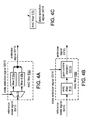
- FIG. 4A shows a block diagram of an adaptive implementation F50 of filter F10.
- FIG. 4B shows a block diagram of an adaptive implementation F60 of filter F10.
- FIG. 4C shows a block diagram of an adaptive implementation F70 of filter F10.
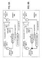
- FIG. 5A shows a block diagram of an implementation A12 of apparatus A10.
- FIG. 5B shows a block diagram of an implementation A22 of apparatus A20.
- FIG. 6A shows a block diagram of an implementation A14 of apparatus A10.
- FIG. 6B shows a block diagram of an implementation A16 of apparatus A12 and A14.
- FIG. 7 shows a block diagram of an implementation A30 of apparatus A16 and A22.
- FIG. 8A shows a block diagram of an ANC filter F 100 as an implementation of filter F10.
- FIG. 8B shows a block diagram of ANC filter F100 as an implementation of filter F20.
- FIG. 9 shows a block diagram of an implementation A40 of apparatus A16.
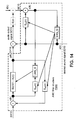
- FIG. 10 shows a block diagram of a structure FS10 that includes control block CB32 and an adaptive implementation F110 of ANC filter F100 in a feed-forward arrangement.
- FIG. 11 shows a block diagram of ANC filter structure FS10 in a feedback arrangement.
- FIG. 12 shows a block diagram of a simplified implementation FS20 of adaptive structure FS10.
- FIG. 13 shows a block diagram of another simplified implementation FS30 of adaptive structure FS10.
- FIGS. 14 , 15 , 16 , and 17 show alternative simplified adaptive ANC structures.
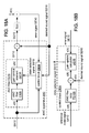
- FIG. 18A shows a block diagram of an adaptive implementation A50 of feedforward ANC apparatus A10.
- FIG. 18B shows a block diagram of control block CB34.
- FIG. 19A shows a block diagram of an adaptive implementation A60 of feedback ANC apparatus A20.
- FIG. 19B shows a block diagram of control block CB36.
- FIG. 20A shows a block diagram of an implementation AP10 of ANC apparatus A10.
- FIG. 20B shows a block diagram of an implementation AP20 of ANC apparatus A20.
- FIG. 21A shows a block diagram of an implementation PAD12 of PDM analog-to-digital converter PAD 10.
- FIG. 21B shows a block diagram of an implementation IN12 of integrator IN10.
- FIG. 22A shows a flowchart of a method M100 according to a general configuration.
- FIG. 22B shows a block diagram of an apparatus MF100 according to a general configuration.
- FIG. 22C shows a block diagram of an implementation AP112 of adaptive ANC apparatus A12.
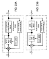
- FIG. 23A shows a block diagram of an implementation PD20 of PDM converter PD10.
- FIG. 23B shows a block diagram of an implementation PD30 of converter PD20.
- FIG. 24 shows a third-order implementation PD22 of converter PD20.
- FIG. 25 shows a third-order implementation PD32 of converter PD30.
- FIG. 26 shows a block diagram of an implementation AP122 of adaptive ANC apparatus A22.
- FIG. 27 shows a block diagram of an implementation AP114 of adaptive ANC apparatus A14.
- FIG. 28 shows a block diagram of an implementation AP116 of adaptive ANC apparatus A16.
- FIG. 29 shows a block diagram of an implementation AP130 of adaptive ANC apparatus A30.
- FIG. 30 shows a block diagram of an implementation AP140 of adaptive ANC apparatus A40.
- FIG. 31A shows an example of a connection diagram between an adaptable ANC filter operating on a fixed hardware configuration and an associated ANC filter adaptation routine operating in software.
- FIG. 31B shows a block diagram of an ANC apparatus AP200.
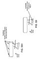
- FIG. 32A shows a cross-section of an earcup EC10.
- FIG. 32B shows a cross-section of an implementation EC20 of earcup EC10.
- FIG. 32C shows a cross-section of an implementation EC30 of earcup EC20.
- FIGS. 33A to 33D show various views of a multi-microphone wireless headset D100.
- FIGS. 33E to 33G show various views of an implementation D102 of headset D100.
- FIG. 33H shows four examples of locations within device D100 at which instances of reference microphones MR10 may be located.
- FIG. 33I shows an example of a location within device D100 at which error microphone ME 10 may be located.
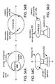
- FIGS. 34A to 34D show various views of a multi-microphone wireless headset D200.
- FIGS. 34E and 34F show various views of an implementation D202 of headset D200.
- FIG. 35 shows a diagram of various standard orientations of a headset 63.
- FIG. 36 shows a top view of headset D100 mounted on a user's ear.
- FIG. 37A shows a diagram of a communications handset H100.
- FIG. 37B shows a diagram of an implementation H110 of handset H100.
- the principles described herein may be applied, for example, to a headset or other communications or sound reproduction device that is configured to perform an ANC operation.
- the term “signal” is used herein to indicate any of its ordinary meanings, including a state of a memory location (or set of memory locations) as expressed on a wire, bus, or other transmission medium.
- the term “generating” is used herein to indicate any of its ordinary meanings, such as computing or otherwise producing.
- the term “calculating” is used herein to indicate any of its ordinary meanings, such as computing, evaluating, smoothing, and/or selecting from a plurality of values.
- the term “obtaining” is used to indicate any of its ordinary meanings, such as calculating, deriving, receiving (e.g., from an external device), and/or retrieving (e.g., from an array of storage elements).
- the term “comprising” is used in the present description and claims, it does not exclude other elements or operations.
- the term “based on” (as in “A is based on B") is used to indicate any of its ordinary meanings, including the cases (i) “based on at least” (e.g., "A is based on at least B") and, if appropriate in the particular context, (ii) "equal to” (e.g., "A is equal to B”).
- the term “in response to” is used to indicate any of its ordinary meanings, including “in response to at least.”
- any disclosure of an operation of an apparatus having a particular feature is also expressly intended to disclose a method having an analogous feature (and vice versa), and any disclosure of an operation of an apparatus according to a particular configuration is also expressly intended to disclose a method according to an analogous configuration (and vice versa).
- configuration may be used in reference to a method, apparatus, and/or system as indicated by its particular context.
- method means
- process means
- procedure means “technique”
- apparatus” and “device” are also used generically and interchangeably unless otherwise indicated by the particular context.
- An ANC apparatus usually has a microphone arranged to capture a reference acoustic noise signal from the environment and/or a microphone arranged to capture an acoustic error signal after the noise cancellation.
- the ANC apparatus uses the microphone input to estimate the noise at that location and produces an antinoise signal which is a modified version of the estimated noise.
- the modification typically includes filtering with phase inversion and may also include gain amplification.
- FIG. 1A shows a block diagram of an example A10 of an ANC apparatus that includes a feedforward ANC filter F10 and a reference microphone MR10 that is disposed to sense ambient noise.
- Filter F10 is arranged to receive a reference noise signal SX10 that is based on a signal produced by reference microphone MR10 and to produce a corresponding antinoise signal SY10.
- Apparatus A10 also includes a loudspeaker LS10 that is configured to produce an acoustic signal based on antinoise signal SY10.
- Loudspeaker LS10 is arranged to direct the acoustic signal at or even into the user's ear canal such that the ambient noise is attenuated or canceled before reaching the user's eardrum (also referred to as the "quiet zone").
- Apparatus A10 may also be implemented to produce reference noise signal SX10 based on information from signals from more than one instance of reference microphone MR10 (e.g., via a filter configured to perform a spatially selective processing operation, such as beamforming, blind source separation, gain and/or phase analysis, etc.).
- an ANC apparatus may be configured to use one or more microphones (e.g., reference microphone MR10) to pick up acoustic noise from the background.
- microphones e.g., reference microphone MR10
- Another type of ANC system uses a microphone (possibly in addition to a reference microphone) to pick up an error signal after the noise reduction.
- An ANC filter in a feedback arrangement is typically configured to inverse the phase of the error signal and may also be configured to integrate the error signal, equalize the frequency response, and/or to match or minimize the delay.
- FIG. 1B shows a block diagram of an example A20 of an ANC apparatus that includes a feedback ANC filter F20 and an error microphone ME 10 that is disposed to sense sound at a user's ear canal, including sound (e.g., an acoustic signal based on antinoise signal SY10) produced by loudspeaker LS10.
- Filter F20 is arranged to receive an error signal SE10 that is based on a signal produced by error microphone ME10 and to produce a corresponding antinoise signal SY10.
- the ANC filter e.g., filter F10, filter F20
- the ANC filter e.g., filter F10, filter F20
- Signal processing operations such as time delay, gain amplification, and equalization or lowpass filtering may be performed to achieve optimal noise cancellation.
- the ANC filter may be desirable to configure the ANC filter to high-pass filter the signal (e.g., to attenuate high-amplitude, low-frequency acoustic signals). Additionally or alternatively, it may be desirable to configure the ANC filter to low-pass filter the signal (e.g., such that the ANC effect diminishes with frequency at high frequencies).
- the processing delay caused by the ANC filter should not exceed a very short time (typically about thirty to sixty microseconds).
- Filter F10 includes a digital filter, such that ANC apparatus A10 will typically be configured to perform analog-to-digital conversion on the signal produced by reference microphone MR10 to produce reference noise signal SX10 in digital form.
- filter F20 includes a digital filter, such that ANC apparatus A20 will typically be configured to perform analog-to-digital conversion on the signal produced by error microphone ME10 to produce error signal SE10 in digital form.
- Examples of other preprocessing operations that may be performed by the ANC apparatus upstream of the ANC filter in the analog and/or digital domain include spectral shaping (e.g., low-pass, high-pass, and/or band-pass filtering), echo cancellation (e.g., on error signal SE10), impedance matching, and gain control.
- the ANC apparatus e.g., apparatus A10 may be configured to perform a high-pass filtering operation (e.g., having a cutoff frequency of 50, 100, or 200 Hz) on the signal upstream of the ANC filter.
- the ANC apparatus will typically also include a digital-to-analog converter (DAC) arranged to convert antinoise signal SY10 to analog form upstream of loudspeaker LS10.
- DAC digital-to-analog converter
- desired sound signals include a received (i.e. far-end) voice communications signal, a music or other multimedia signal, and a sidetone signal.
- FIG. 2A shows a block diagram of a finite-impulse-response (FIR) implementation AF12 of feedforward ANC filter AF10.
- a second-order FIR filter is shown in this example, an FIR implementation of filter AF10 may include any number of FIR filter stages (i.e., any number of filter coefficients), depending on factors such as maximum allowable delay.
- each of the filter coefficients may be implemented using a polarity switch (e.g., an XOR gate).
- FIG. 2B shows a block diagram of an alternate implementation AF14 of FIR filter AF12.
- Feedback ANC filter AF20 may be implemented as an FIR filter according to the same principles discussed above with reference to FIGS. 2A and 2B .
- FIG. 3 shows a block diagram of an infinite-impulse-response (IIR) implementation AF16 of filter AF10.
- the filter coefficients i.e., feedforward gain factors b 0 , b 1 , and b 2 and feedback gain factors a 1 and a 2 ).
- an IIR implementation of filter AF10 may include any number of filter stages (i.e., any number of filter coefficients) on either of the feedback side (i.e., the denominator of the transfer function) and the feedforward side (i.e., the numerator of the transfer function), depending on factors such as maximum allowable delay.
- each of the filter coefficients may be implemented using a polarity switch (e.g., an XOR gate).
- Feedback ANC filter AF20 may be implemented as an IIR filter according to the same principles discussed above with reference to FIG. 3 . Either of filters F10 and F20 may also be implemented as a series of two or more FIR and/or IIR filters.
- An ANC filter may be configured to have a filter state that is fixed over time or, alternatively, a filter state that is adaptable over time.
- An adaptive ANC filtering operation can typically achieve better performance over an expected range of operating conditions than a fixed ANC filtering operation. In comparison to a fixed ANC approach, for example, an adaptive ANC approach can typically achieve better noise cancellation results by responding to changes in the ambient noise and/or in the acoustic path.
- FIG. 4A shows a block diagram of an adaptable implementation F50 of ANC filter F10 that includes a plurality of different fixed-state implementations F15a and F15b of filter F10. Filter F50 is configured to select one among the component filters F15a and F15b according to a state of state selection signal SS10.
- filter F50 includes a selector SL10 that directs reference noise signal SX10 to the filter indicated by the current state of state selection signal SS10.
- ANC filter F50 may also be implemented to include a selector that is configured to select the output of one of the component filters according to the state of selection signal SS10.
- selector SL10 may also be present, or may be omitted such that all of the component filters receive reference noise signal SX10.
- the plurality of component filters of filter F50 may differ from one another in terms of one or more response characteristics, such as gain, low-frequency cutoff frequency, low-frequency rolloff profile, high-frequency cutoff frequency, and/or high-frequency rolloff profile.
- Each of the component filters F15a and F15b may be implemented as an FIR filter, as an IIR filter, or as a series of two or more FIR and/or IIR filters. Although two selectable component filters are shown in the example of FIG. 4A , any number of selectable component filters may be used, depending on factors such as maximum allowable complexity.
- Feedback ANC filter AF20 may be implemented as an adaptable filter according to the same principles discussed above with reference to FIG. 4A .
- FIG. 4B shows a block diagram of another adaptable implementation F60 of ANC filter F10 that includes a fixed-state implementation F15 of filter F10 and a gain control element GC10.
- Filter F15 may be implemented as an FIR filter, as an IIR filter, or as a series of two or more FIR and/or IIR filters.
- Gain control element GC10 is configured to amplify and/or attenuate the output of ANC filter F15 according to a filter gain update indicated by the current state of state selection signal SS10.
- Gain control element GC10 may be implemented such that the filter gain update is a linear or logarithmic gain factor to be applied to the output of filter F 15, or a linear or logarithmic change (e.g., an increment or decrement) to be applied to a current gain factor of gain control element GC10.
- gain control element GC10 is implemented as a multiplier.
- gain control element GC10 is implemented as a variable-gain amplifier.
- Feedback ANC filter AF20 may be implemented as an adaptable filter according to the same principles discussed above with reference to FIG. 4B .
- FIG. 4C shows a block diagram of an adaptable implementation F70 of ANC filter F10 in which the state of state selection signal SS10 indicates a value for each of one or more of the filter coefficients.
- Filter F70 may be implemented as an FIR filter or as an IIR filter.
- filter F70 may be implemented as a series of two or more FIR and/or IIR filters in which one or more (possibly all) of the filters are adaptable and the rest have fixed coefficient values.
- ANC filter F70 that includes an IIR filter
- one or more (possibly all) of the feedforward filter coefficients and/or one or more (possibly all) of the feedback filter coefficients may be adaptable.
- Feedback ANC filter AF20 may be implemented as an adaptable filter according to the same principles discussed above with reference to FIG. 4C .
- An ANC apparatus that includes an instance of adaptable filter F70 may be configured such that the latency introduced by the filter is adjustable (e.g., according to the current state of selection signal SS10).
- filter F70 may be configured such that the number of delay stages is variable according to the state of selection signal SS10. In one such example, the number of delay stages is reduced by setting the values of the highest-order filter coefficients to zero.
- adjustable latency may be desirable especially for feedforward ANC designs (e.g., implementations of apparatus A10).
- feedforward ANC filter F10 may also be configured as an implementation of two or more among component-selectable filter F50, gain-selectable filter F60, and coefficient value-selectable filter F70, and that feedback ANC filter F20 may be configured according to the same principles.
- FIG. 5A shows a block diagram of an implementation A12 of ANC apparatus A10 that includes an adaptable implementation F12 of feedforward ANC filter F10 (e.g., an implementation of filter F50, F60, and/or F70).
- Apparatus A12 also includes a control block CB10 that is configured to generate state selection signal SS10 based on information from reference noise signal SX10. It may be desirable to implement control block CB10 as a set of instructions to be executed by a processor (e.g., a digital signal processor or DSP).
- a processor e.g., a digital signal processor or DSP
- 5B shows a block diagram of an implementation A22 of ANC apparatus A20 that includes an adaptable implementation F22 of feedback ANC filter F20 and a control block CB20 that is configured to generate state selection signal SS10 based on information from error signal SE10. It may be desirable to implement control block CB20 as a set of instructions to be executed by a processor (e.g., a DSP).
- a processor e.g., a DSP
- FIG. 6A shows a block diagram of an implementation A14 of ANC apparatus A10 that includes error microphone ME10 and an instance of control block CB20 configured to generate state selection signal SS10 based on information from error signal SE10.
- FIG. 6B shows a block diagram of an implementation A16 of ANC apparatus A12 and A14 that includes an implementation CB30 of control block CB10 and CB20 that is configured to generate state selection signal SS10 based on information from reference noise signal SX10 and information from error signal SE10. It may be desirable to implement control block CB30 as a set of instructions to be executed by a processor (e.g., a DSP). It may be desirable to perform an echo cancellation operation on error signal SE10 upstream of control block CB20 or CB30.
- a processor e.g., a DSP
- control block CB30 may be desirable to configure control block CB30 to generate state selection signal SS10 according to an implementation of a least-mean-squares (LMS) algorithm, which class includes filtered-reference (“filtered-X”) LMS, filtered-error (“filtered-E”) LMS, filtered-U LMS, and variants thereof (e.g., subband LMS, step size normalized LMS, etc.).
- LMS least-mean-squares
- control block CB30 may be desirable to configure control block CB30 to generate state selection signal SS10 to indicate an updated value for each of one or more of the filter coefficients according to an implementation of the filtered-U LMS algorithm.
- FIG. 7 shows a block diagram of an implementation A30 of apparatus A16 and A22 that includes a hybrid ANC filter F40.
- Filter F40 includes instances of adaptable feedforward ANC filter F 12 and adaptable feedback ANC filter F22.
- the outputs of filters F12 and F22 are combined to produce antinoise signal SY10.
- Apparatus A30 also includes an instance of control block CB30 that is configured to provide an instance SS10a of state selection signal SS10 to filter F12, and an instance of control block CB20 that is configured to provide an instance SS10b of state selection signal SS10 to filter F22.
- FIG. 8A shows a block diagram of an ANC filter F100 that includes a feed-forward IIR filter FF10 and a feedback IIR filter FB10.
- Filter F100 may be arranged to perform a feed-forward ANC operation (i.e., as an implementation of ANC filter F10) or a feedback ANC operation (i.e., as an implementation of ANC filter F20).
- FIG. 8A shows filter F100 arranged as an implementation of feedforward ANC filter F10.
- feedback IIR filter FB10 may act to cancel acoustic leakage from reference microphone MR10.
- the label k denotes a time-domain sample index
- x(k) denotes reference noise signal SX10
- y(k) denotes antinoise signal SY10
- y B (k) denotes a feedback signal produced by feedback filter FB10.
- FIG. 8B shows filter F100 arranged as an implementation of feedback ANC filter F20.
- feedback IIR filter FB10 may act to remove antinoise signal SY10 from error signal SE10.
- feedforward filter FF10 may be implemented as an FIR filter by setting A(z) to zero (i.e., by setting each of the feedback coefficient values a of A(z) to zero).
- feedback filter FB10 may be implemented as an FIR filter by setting V(z) to zero (i.e., by setting each of the feedback coefficient values v of V(z) to zero).
- feed-forward filter FF10 and feedback filter FB10 may be implemented to have fixed filter coefficients.
- a feed-forward IIR filter and a feedback IIR filter form a full feedback IIR-type structure (e.g., a filter topology that includes a feedback loop formed by a feed-forward filter and a feedback filter, each of which may be an IIR filter).
- FIG. 9 shows a block diagram of an implementation A40 of apparatus A16 that includes an adaptable implementation F110 of ANC filter F100 in a feed-forward arrangement (i.e., as an implementation of filter F12).
- adaptable filter F110 includes an adaptable implementation FF12 of feedforward filter FF10 and an adaptable implementation FB12 of feedback filter FB10.
- Each of adaptable filters FF12 and FB12 may be implemented according to any of the principles discussed above with reference to adaptable filters F50, F60, and F70.
- Apparatus A40 also includes an implementation CB32 of control block CB30 that is configured to provide an instance SS10ff of state selection signal SS10 to filter FF12 and an instance SS10fb of state selection signal SS10 to filter FB12, where signals SS10ff and SS10fb are based on information from reference noise signal SX10 and error signal SE10. It may be desirable to implement control block CB32 as a set of instructions to be executed by a processor (e.g., a DSP).
- a processor e.g., a DSP
- FIG. 10 shows a block diagram of a structure FS10 that includes implementations of filter F110 and control block CB32 and is arranged in a feedforward arrangement.
- the unshaded boxes denote the filtering operations B(z)/(1 - A(z)) and W(z)/(1 - V(z)) within filter F110, and the shaded boxes denote adaptation operations within control block CB32.
- the transfer function S est (z) which may be calculated offline, estimates the secondary acoustic path S(z) between loudspeaker LS10 and error microphone ME10, including the responses of the microphone preamplifier and the loudspeaker amplifier.
- the label d(k) denotes the acoustic noise to be cancelled at the location of error microphone ME10, and the functions B(z) and S est (z) are copied to various locations within control block CB32 to generate intermediate signals.
- the blocks LMS_B and LMS_A denote operations for calculating updated coefficient values for B(z) and A(z), respectively (i.e., state selection signal SS10ff), according to LMS (least-mean-squares) principles.
- the blocks LMS_W and LMS_V denote operations for calculating updated coefficient values for W(z) and V(z), respectively (i.e., state selection signal SS10fb), according to LMS (least-mean-squares) principles.
- Control block CB32 may be implemented such that the numerator and denominator coefficients of both of feedforward filter FF12 and feedback IIR filter FB12 are updated simultaneously with respect to the signal being filtered.
- FIG. 11 shows a block diagram of ANC filter structure FS10 in a feedback arrangement.
- An algorithm for operating control block CB32 to generate updated values for filter coefficients of filter F110 may be derived by applying principles of the filtered-U LMS methodology to the structure of filter F110. Such an algorithm may be derived in two steps: a first step that derives the coefficient values without considering S(z), and a second step in which the derived coefficient values are convolved by S(z).
- a fully adaptive structure as shown in FIGS. 10 and 11 may be appropriate for an application in which sufficient computational resources are available, such as a handset application.
- various forms of simplified adaptive ANC filter structures may be derived based on this fully IIR adaptive ANC algorithm.
- These simplified adaptive ANC algorithms can be tailored to different applications (e.g., resource-limited applications).
- FIG. 12 shows a block diagram of such a simplified implementation FS20 of adaptive structure FS10.
- FIG. 13 shows a block diagram of such a simplified implementation FS30 of adaptive structure FS10.
- control block CB32 may be configured to perform the adaptation operations LMS_B and LMS_A according to an implementation of the filtered-U LMS algorithm, such as the following: b i ⁇ b i + ⁇ ⁇ x 2 k ⁇ s k , for all b i in B z a i ⁇ a i + ⁇ ⁇ y 2 ⁇ k - 1 ⁇ s k , for all a i in A z where x' and y' denote the results of applying the transfer function S est (z) to the signals SX10 and SY10, respectively.
- W(z)/(1 - V(z)) may be expected to converge to S(z).
- the adaptation may make these functions diverge.
- an estimate S est (z) that is calculated offline may not be accurate. It may be desirable to configure the adaptation to minimize the residual error signal such that a noise reduction goal may still be achieved (e.g., in a minimum mean square error (MMSE) sense).
- MMSE minimum mean square error
- desired sound signal SD10 is a reproduced audio signal, such as a far-end voice communications signal (e.g., a telephone call) or a multimedia signal (e.g., a music signal, which may be received via broadcast or decoded from a stored file).
- desired sound signal SD10 is a sidetone signal that carries the user's own voice.
- FIGS. 14 , 15 , 16 , and 17 show alternative simplified adaptive ANC structures for such implementations of apparatus A40 in which S est (z) is adapted.
- the adaptation operation LMS_S supports cancellation of the desired sound signal SD10 (indicated as a(k)) and online estimation of S(z).
- an implementation FS40 of adaptive structure FS10 is configured such that the coefficient values W(z)/(1 - V(z)) of feedback filter FB10 are equal to the adapted secondary path estimate S est (z).
- FIG. 15 shows a similar implementation FS50 of adaptive structure FS10 in a feedback arrangement.
- control block CB32 may be configured to perform the adaptation operation LMS_B according to an implementation of the filtered-X LMS algorithm, such as the following: b i ⁇ b i + ⁇ ⁇ x 2 k ⁇ s k , for all b i in B z where x' denotes the results of applying the transfer function S est (z) to the signal SX10.
- control block CB32 may be configured to perform the adaptation operations LMS_B and LMS_A according to an implementation of the filtered-U LMS algorithm (e.g., as described above).
- both of filters FF10 and FB10 may be realized as an implementation of component-selectable filter F50, or one may be realized as an implementation of filter F50 and the other may be fixed.
- filters FF10 and FB10 may be implemented as an implementation of component-selectable filter F50, or one may be realized as an implementation of filter F50 and the other may be fixed.
- filters FF10 and FB10 may be implemented with fixed coefficient values and update the filter gain only. In such case, it may be desirable to implement a simplified ANC algorithm for gain and phase adaptation.
- FIG. 18A shows a block diagram of an adaptive implementation A50 of feedforward ANC apparatus A10 that includes ANC filter FG10 and a control block CB34.
- Filter FG10 is an implementation of gain-selectable filter F60 that includes a fixed-coefficient implementation F105 of filter F100.
- FIG. 18B shows a block diagram of control block CB34, which includes a copy FC105 of ANC filter F105 and a gain update calculator UC10.
- Gain update calculator UC10 is configured to generate state selection signal SS10 to include filter gain update information (e.g., updated gain factor values or changes to existing gain factor values) that is based on information from error signal SE10 and information from a sum q(k) of reference noise signal SX10, as filtered by filter copy FC105, and desired sound signal SD10. It may be desirable to implement apparatus A50 such that ANC filter FG10 is implemented in hardware (e.g., within an application-specific integrated circuit (ASIC) or field-programmable gate array (FPGA)), and control block CB34 is implemented in software (e.g., as instructions for execution by a processor, such as a DSP).
- ASIC application-specific integrated circuit
- FPGA field-programmable gate array
- FIG. 19A shows a block diagram of an adaptive implementation A60 of feedback ANC apparatus A20 that includes ANC filter FG20 and a control block CB36.
- Filter FG20 is a gain-selectable implementation of filter F20, according to the principles described herein with respect to gain-selectable filter F60, that includes a fixed-coefficient implementation F115 of filter F100.
- Filter FG20 also includes a filter FSE10, which is an estimate S est (z) of the transfer function of the secondary acoustic path.
- FIG. 19B shows a block diagram of control block CB36, which includes a copy FC115 of ANC filter F115 and an instance of gain update calculator UC10.
- gain update calculator UC10 is arranged to generate state selection signal SS10 to include filter gain update information (e.g., updated gain factor values or changes to existing gain factor values) that is based on information from error signal SE10 and information from a sum q(k) of x(k) (here, a sum of desired sound signal SD10, as filtered by secondary path estimate S est (z), and error signal SE10), as filtered by filter copy FC115, and desired sound signal SD10.
- filter gain update information e.g., updated gain factor values or changes to existing gain factor values
- filter gain update information e.g., updated gain factor values or changes to existing gain factor values
- filter gain update information e.g., updated gain factor values or changes to existing gain factor values
- Gain update calculator UC10 as shown in FIGS. 18B and 19B may be configured to operate according to an SNR-based gain curve.
- calculator UC10 may be configured to set the gain value G(k) equal to one if the voice SNR is above (alternatively, not less than) a threshold value (e.g., to reduce ANC artifacts), and otherwise to update G(k) according to a subband LMS scheme as described in the following operation.
- M denotes the number of subbands
- K denotes the number of samples per frame (for a frame length of, e.g., ten or twenty milliseconds)
- m denotes a subband index.
- An estimate of the secondary acoustic path S(z) is not needed for this adaptation.
- Each of the above gain and energy estimate updates may be repeated at each sample k or at some less frequent time interval (e.g., once per frame).
- Such an algorithm is based on the assumption that within each subband of the secondary path S(z), changes occur only in gain and phase, such that these changes may be compensated by updating the gain G. It may be desirable to configure the adaptive algorithm to operate only on an ANC-related spectrum region (e.g., about 200-2000 Hz).
- Filter stability is not an issue in fixed-coefficient structures (e.g., filter F105 as shown in FIG. 18A , filter F115 as shown in FIG. 19A ).
- an adaptive structure e.g., a structure that includes a fully adaptable implementation of filter F110
- Example filter initialization methods include using a system identification tool to calculate an acoustic path estimate S est (z) offline, and obtaining FIR filter coefficient values using an adaptive LMS algorithm.
- the FIR coefficient values may be converted into an initial set of IIR coefficient values using a balanced model reduction technique.
- ⁇ step size
- Selecting different ⁇ values for the feedforward (numerator) and feedback (denominator) coefficient values may also help to maintain IIR filter stability. For example, it may be desirable to select a ⁇ value for each filter denominator that is about one-tenth of the ⁇ value for the corresponding filter numerator.
- control block e.g., control blocks CB10, CB20, CB30, and CB32
- the filter is stable if and only if a a > 0 , a a - 2 > 0 , a a - 4 > 0 , - a 1 > 0 D 1 > 0 , D 2 > 0 , D 2 > 0.
- D i denote Hurwitz determinants
- a i are the denominator coefficients of the IIR filter.
- a bilinear transform may be used to translate z-domain coefficients into s-domain coefficients. For a feedback arrangement, it may also be desirable to meet the closed-loop stability criterion.
- the delay required by an ANC apparatus to process the input noise signal and generate a corresponding antinoise signal should not exceed a very short time.
- Implementations of ANC apparatus for small mobile devices, such as handsets and headsets typically require a very short processing delay or latency (e.g., about thirty to sixty microseconds) for the ANC operation to be effective. This delay requirement puts a great constraint on the possible processing and implementation method of the ANC system. While the signal processing operations typically used in an ANC apparatus are straightforward and well defined, it may be difficult to implement these operations while meeting the delay constraint.
- analog circuits may be implemented to have very short processing delays, an ANC operation is typically implemented for a small device (e.g., a headset or handset) using analog signal processing circuits.
- a small device e.g., a headset or handset
- Many commercial and/or military devices that include short-delay, nonadaptive analog ANC processing are currently in use.
- An adaptive ANC apparatus as described above (e.g., apparatus A12, A14, A16, A22, A30, A40, A50, or A60) may be implemented, for example, such that both of the ANC filtering and the filter adaptation are performed in software (e.g., as respective sets of instructions executing on a processor, such as a DSP).
- an adaptive ANC apparatus may be implemented by combining hardware that is configured to filter an input noise signal to generate a corresponding antinoise signal (e.g., a pulse-code modulation (PCM)-domain coder-decoder or "codec”) with a DSP that is configured to execute an adaptive algorithm in software.
- PCM pulse-code modulation
- codec codec
- the operations of converting an analog signal to a PCM digital signal for processing and converting the processed signal back to analog introduce a delay that is typically too large for optimal ANC operation.
- Typical bit widths for a PCM digital signal include eight, twelve, and sixteen bits
- typical PCM sampling rates for audio communications applications include eight, eleven, twelve, sixteen, thirty-two, and forty-eight kilohertz.
- each sample has a duration of about 125, 62.5, and 21 microseconds, respectively.
- Application of such an apparatus would be limited, as a substantial processing delay could be expected, and the ANC performance would typically be limited to cancelling repetitive noise.
- a PDM-domain signal typically has a low resolution (e.g., a bit width of one, two, or four bits) and a very high sampling rate (e.g., on the order of 100 kHz, 1 MHz, or even 10 MHz).
- the PDM sampling rate may be eight, sixteen, thirty-two, or sixty-four times the Nyquist rate.
- an oversampling rate of 64 yields a PDM sampling rate of 512 kHz.
- an oversampling rate of 64 yields a PDM sampling rate of 1 MHz.
- an oversampling rate of 256 yields a PDM sampling rate of 12.288 MHz.
- a PDM-domain digital ANC apparatus may be implemented to introduce a minimal system delay (e.g., about twenty to thirty microseconds). Such a technique may be used to implement a high-performance ANC operation. For example, such an apparatus may be arranged to apply signal processing operations directly to the low-resolution over-sampled signals from an analog-to-PDM analog-to-digital converter (ADC) and to send the result directly to a PDM-to-analog digital-to-analog converter (DAC).
- ADC analog-to-PDM analog-to-digital converter
- DAC PDM-to-analog digital-to-analog converter
- FIG. 20A shows a block diagram of an implementation AP10 of ANC apparatus A10.
- Apparatus AP10 includes a PDM ADC PAD10 that is configured to convert reference noise signal SX10 from the analog domain to a PDM domain.
- Apparatus AP10 also includes an ANC filter FP10 that is configured to filter the converted signal in the PDM domain.
- Filter FP10 is an implementation of filter F10 that may be realized as a PDM-domain implementation of any of filters F15, F50, F60, F100, F105, FG10, AF12, AF14, and AF16 as disclosed herein.
- Filter FP10 may be implemented as an FIR filter, as an IIR filter, or as a series of two or more FIR and/or IIR filters.
- Apparatus AP10 also includes a PDM DAC PDA10 that is configured to convert antinoise signal SY10 from the PDM domain to the analog domain.
- FIG. 20B shows a block diagram of an implementation AP20 of ANC apparatus A20.
- Apparatus AP20 includes an instance of PDM ADC PAD10 that is arranged to convert error signal SE10 from the analog domain to a PDM domain and an ANC filter FP20 that is configured to filter the converted signal in the PDM domain.
- Filter FP20 is an implementation of filter F20 that may be realized as a PDM-domain implementation of any of filters AF12, AF14, AF16, and FG20 as disclosed herein and/or according to the principles described herein with reference to any of filters F15, F50, F60, F100, and F105.
- Apparatus AP20 also includes an instance of PDM DAC PDA10 that is arranged to convert antinoise signal SY10 from the PDM domain to the analog domain.
- PDM DAC PDA10 may be implemented as an analog low-pass filter arranged to convert antinoise signal SY10 from the PDM domain to the analog domain. For a case in which the input to PDM DAC PDA10 is wider than one bit, it may be desirable for PDM DAC PDA10 first to reduce the signal width to one bit (e.g., to include an instance of PDM converter PD30 as described below). It may be desirable to implement PDM ADC PAD 10 as a sigma-delta modulator AD10 (also called a "delta-sigma modulator"). Any sigma-delta modulator that is deemed suitable for the particular application may be used.
- 21A shows a block diagram of one example PAD 12 of an implementation of PDM ADC PAD 10 that includes an integrator IN10, a comparator CM10 configured to digitize its input signal by comparing it to a threshold value, a latch LT10 (e.g., a D-type latch) configured to operate at the PDM sampling rate according to a clock CK10, and a dequantizer DQ10 (e.g, a switch) configured to convert the output digital signal to an analog signal for feedback.
- a latch LT10 e.g., a D-type latch
- DQ10 e.g, a switch
- integrator IN10 may be configured to perform one level of integration. Integrator IN10 may also be configured to perform multiple levels of integration for higher-order operation.
- FIG. 21B shows a block diagram of an implementation IN12 of integrator IN10 that may be used for third-order sigma-delta modulation. Integrator IN12 includes a cascade of single integrators IS10-0, IS10-1, IS10-2 whose outputs are weighted by respective gain factors (filter coefficients) c0, c1, c2 and then summed. Gain factors c0-c2 are optional, and their values may be selected to provide a desired noise-shaping profile.
- gain factors c0-c2 may be implemented using polarity switches (e.g., XOR gates).
- Integrator IN10 may be implemented for second-order modulation, or for higher-order modulation, in similar fashion.
- PDM-domain ANC filters FP10 and FP20 may be implemented in digital hardware (e.g., a fixed configuration of logic gates, such as an FPGA or ASIC) rather than in software (e.g., instructions executed by a processor, such as a DSP).
- digital hardware e.g., a fixed configuration of logic gates, such as an FPGA or ASIC
- software e.g., instructions executed by a processor, such as a DSP
- implementation of a PDM-domain algorithm in software e.g., for execution by a processor, such as a DSP
- a custom digital hardware implementation may be preferred.
- An ANC filtering technique that adapts the ANC filter dynamically can typically achieve a higher noise reduction effect than a fixed ANC filtering technique.
- an adaptive algorithm in digital hardware may require a relatively high complexity.
- An adaptive ANC algorithm typically requires much more computational complexity than a non-adaptive ANC algorithm. Consequently, PDM-domain ANC implementations are generally limited to fixed filtering (i.e., nonadaptive) approaches.
- One reason for this practice is the high cost of implementing an adaptive signal processing algorithm in digital hardware.
- ANC filtering in a PDM domain may be implemented using digital hardware, which may provide a minimal delay (latency) and/or optimal ANC operation.
- PDM-domain processing may be combined with an implementation of an adaptive ANC algorithm in a PCM domain using software (e.g., instructions for execution by a processor, such as a DSP), as the adaptive algorithm may be less sensitive to delay or latency incurred by converting a signal to the PCM domain.
- hybrid adaptive ANC principles may be used to implement an adaptive ANC apparatus that has one or more of the following features: minimum processing delay (e.g., due to PDM-domain filtering), adaptive operation (e.g., due to adaptive algorithm in a PCM domain), a much lower cost of implementation (e.g., due to much lower cost of implementing an adaptive algorithm in the PCM domain than in hardware, and/or ability to execute the adaptive algorithm on a DSP, which is available in most communications devices).
- minimum processing delay e.g., due to PDM-domain filtering
- adaptive operation e.g., due to adaptive algorithm in a PCM domain
- a much lower cost of implementation e.g., due to much lower cost of implementing an adaptive algorithm in the PCM domain than in hardware, and/or ability to execute the adaptive algorithm on a DSP, which is available in most communications devices.
- An adaptive ANC method is disclosed that may be implemented at a low hardware cost.
- This method includes performing high-speed, low-latency filtering in a high-sampling-rate or "oversampled" domain (e.g., a PDM domain). Such filtering may be most easily implemented in hardware.
- the method also includes performing low-speed, high-latency adaptation of the filter in a low-sampling-rate domain (e.g., a PCM domain). Such adaptation may be most easily implemented in software (e.g., for execution by a DSP).
- the method may be implemented such that the filtering hardware and the adaptation routine share the same input source (e.g., reference noise signal SX10 and/or error signal SE10).
- FIG. 22A shows a flowchart of a method M100 of producing an antinoise signal according to a general configuration that includes tasks T100, T200, and T300.
- Task T100 produces the antinoise signal during a first time interval by applying a digital filter to a reference noise signal in a filtering domain having a first sampling rate.
- the digital filter has a first filter state.
- Task T200 produces the antinoise signal during a second time interval subsequent to the first time interval by applying the digital filter to the reference noise signal in the filtering domain.
- the digital filter has a second filter state that is different than the first filter state.
- Task T300 calculates the second filter state, in an adaptation domain having a second sampling rate that is lower than the first sampling rate, based on information from the reference noise signal and information from an error signal.
- FIG. 22B shows a block diagram of an apparatus MF100 for producing an antinoise signal according to a general configuration.
- Apparatus MF100 includes means G100 (e.g., a PDM-domain filter) for producing the antinoise signal during a first time interval by filtering a reference noise signal, according to a first filter state, in a filtering domain having a first sampling rate, and for producing the antinoise signal during a second time interval subsequent to the first time interval by filtering the reference noise signal in the filtering domain according to a second filter state that is different from the first filter state.
- G100 e.g., a PDM-domain filter
- Apparatus MF100 also includes means G200 (e.g., a control block) for calculating, in an adaptation domain having a second sampling rate that is lower than the first sampling rate, the second filter state based on information from the reference noise signal and information from an error signal.
- means G200 e.g., a control block
- the sampling rate of the high-sampling-rate domain may be at least twice (e.g., at least four, eight, sixteen, 32, 64, 128, or 256 times) the sampling rate of the low-sampling-rate domain.
- the ratio of the high sampling rate to the low sampling rate is also called the "oversampling rate" or OSR.
- the two digital domains may be configured such that the bit width of a signal in the low-sampling-rate domain is greater than (e.g., at least two, four, eight, or sixteen times) the bit width of a signal in the high-sampling-rate domain.
- the low-sampling-rate domain is implemented as a PCM domain and the high-sampling-rate domain is implemented as a PDM domain.
- typical PCM sampling rates for audio communications applications include eight, eleven, twelve, sixteen, thirty-two, and forty-eight kilohertz
- typical OSRs include 4, 8, 16, 32, 64, 128, and 256, and all forty-two combinations of these parameters are expressly contemplated and hereby disclosed.
- these examples are merely illustrative and not limiting.
- the method may be implemented such that both of the low-sampling-rate domain (e.g., in which adaptation is performed in software) and the high-sampling-rate domain (e.g., in which filtering is performed in hardware) are PCM domains.
- the low-sampling-rate domain e.g., in which adaptation is performed in software
- the high-sampling-rate domain e.g., in which filtering is performed in hardware
- adaptation of the ANC filter may typically be performed at a much lower rate (e.g., without high-frequency updates or a very short latency).
- the latency for ANC adaptation i.e., the interval between filter state updates
- Such adaptation may be implemented in a PCM domain to be performed in software (e.g., for execution by a DSP). It may be more cost-effective to implement an adaptive algorithm in software (e.g., for execution by a generic DSP) than to implement a complex hardware solution for such slow processing.
- a software implementation of an adaptive algorithm is typically much more flexible than a hardware implementation.
- FIG. 22C shows a block diagram of an implementation AP112 of adaptive ANC apparatus A12.
- Apparatus AP112 includes an instance of PDM ADC PAD10 that is arranged to convert reference noise signal SX10 from the analog domain to a PDM domain.
- Apparatus AP112 also includes an adaptable ANC filter FP12 that is configured to filter the converted signal in the PDM domain.
- Filter FP12 is an implementation of filter F12 that may be realized as a PDM-domain implementation of any of filters F50, F60, F70, F100, FG10, AF12, AF14, and AF16 as disclosed herein.
- Filter FP12 may be implemented as an FIR filter, as an IIR filter, or as a series of two or more FIR and/or IIR filters.
- Apparatus AP112 also includes an instance of PDM DAC PDA10 that is arranged to convert antinoise signal SY10 from the PDM domain to the analog domain, and an instance of control block CB10 that is arranged to generate state selection signal SS10, based on information from reference noise signal SX10 in the PCM domain.
- Apparatus AP112 also includes a PCM converter PC10 that is configured to convert reference noise signal SX10 from the PDM domain to a PCM domain, and a PDM converter PD10 that is configured to convert state selection signal SS10 from the PCM domain to the PDM domain.
- PCM converter PC10 may be implemented to include a decimator
- PDM converter PD10 may be implemented to include an upsampler (e.g., an interpolator). Conversion between the PCM and PDM domains typically incurs a substantial delay or latency. Such conversion processes may include operations, such as lowpass filtering, downsampling, and/or signal conditioning filtering, that may generate a large delay or latency.
- state selection signal SS10 indicates only a selection among component filters (e.g., of an implementation of component-selectable filter F50) or a gain update (e.g., for an implementation of gain-selectable filter F60), it is possible that upsampling of state selection signal SS10 to the PDM domain (i.e., PDM converter PD10) may be omitted.
- component filters e.g., of an implementation of component-selectable filter F50
- a gain update e.g., for an implementation of gain-selectable filter F60
- FIG. 23A shows a block diagram of an implementation PD20 of PDM converter PD10 (also called a sigma-delta modulator) that may be used to convert an M-bit-wide PCM signal to an N-bit-wide PDM signal.
- Converter PD20 includes an M-bit latch LT20 (e.g., a D-type latch) configured to operate at the PCM sampling rate according to a clock CK20, and a most-significant-N-bits extractor BX10 that outputs the most significant N bits of its digital input as an N-bit-wide signal.
- Converter CO10 also includes an N-bit-to-M-bit converter BC10 (also called an N-bit digital-to-digital converter).
- FIG. 23B shows a block diagram of an M-bits-to-1-bit implementation PD30 of converter PD20.
- Converter PD30 includes an implementation BX12 of extractor BX10 that outputs the MSB of its digital input as a one-bit-wide signal.
- Converter PD30 also includes a 1-bit-to-M-bit implementation BC12 (also called a 1-bit digital-to-digital converter) of converter BC10 that outputs the minimum or maximum M-bit digital value, according to the current state of the output of MSB extractor BX12.
- BC12 also called a 1-bit digital-to-digital converter
- FIG. 24 shows an example PD22 of a third-order implementation of converter PD20.
- Values for the optional coefficients m0-m2 may be selected to provide, for example, a desired noise-shaping performance.
- Converter PD20 may be implemented for second-order modulation, or for higher-order modulation, in similar fashion.
- FIG. 25 shows an example PD32 of a third-order implementation of converter PD30.
- FIG. 26 shows a block diagram of an implementation AP122 of adaptive ANC apparatus A22.
- Apparatus AP122 includes an instance of PDM ADC PAD10 that is arranged to convert error signal SE10 from the analog domain to a PDM domain.
- Apparatus AP122 also includes an adaptable ANC filter FP22 that is configured to filter the converted signal in the PDM domain.
- Filter FP22 is an implementation of filter F22 that may be realized as a PDM-domain implementation of any of filters AF12, AF14, AF16, and FG20 as disclosed herein and/or according to the principles described herein with reference to any of filters F50, F60, F70, and F100.
- Filter FP22 may be implemented as an FIR filter, as an IIR filter, or as a series of two or more FIR and/or IIR filters.
- Apparatus AP122 also includes an instance of PDM DAC PDA10 that is arranged to convert antinoise signal SY10 from the PDM domain to the analog domain, an instance of PCM converter PC 10 that is arranged to convert error signal SE10 from the PDM domain to the PCM domain, an instance of control block CB20 that is arranged to generate state selection signal SS10 based on information from error signal SE10 in the PCM domain, and an instance of PDM converter PD10 that is arranged to convert state selection signal SS10 from the PCM domain to the PDM domain.
- PDM DAC PDA10 that is arranged to convert antinoise signal SY10 from the PDM domain to the analog domain
- PCM converter PC 10 that is arranged to convert error signal SE10 from the PDM domain to the PCM domain
- control block CB20 that is arranged to generate state selection
- FIG. 27 shows a block diagram of an implementation AP114 of adaptive ANC apparatus A14.
- Apparatus AP114 includes an instance of PDM ADC PAD10 that is arranged to convert reference noise signal SX10 from the analog domain to a PDM domain, and an instance of adaptable ANC filter FP 12 that is configured to filter the converted signal in the PDM domain.
- Apparatus AP114 also includes an instance of PDM DAC PDA10 that is arranged to convert antinoise signal SY10 from the PDM domain to the analog domain, a PCM ADC PCA10 that is arranged to convert error signal SE10 from the analog domain to the PCM domain, an instance of control block CB20 that is arranged to generate state selection signal SS10 based on information from error signal SE10 in the PCM domain, and an instance of PDM converter PD10 that is arranged to convert state selection signal SS10 from the PCM domain to the PDM domain.
- PDM DAC PDA10 that is arranged to convert antinoise signal SY10 from the PDM domain to the analog domain
- PCM ADC PCA10 that is arranged to convert error signal SE10 from the analog domain to the PCM domain
- control block CB20 that is arranged to generate state selection signal SS10 based on information from error signal SE10 in the PCM domain
- PDM converter PD10 that is arranged to convert state selection signal SS10 from
- FIG. 28 shows a block diagram of an implementation AP116 of adaptive ANC apparatus A16.
- Apparatus AP116 includes an instance of PDM ADC PAD10 that is arranged to convert reference noise signal SX10 from the analog domain to a PDM domain, and an instance of adaptable ANC filter FP12 that is configured to filter the converted signal in the PDM domain.
- Apparatus AP116 also includes an instance of PDM DAC PDA10 that is arranged to convert antinoise signal SY10 from the PDM domain to the analog domain, a PCM ADC PCA10 that is arranged to convert error signal SE10 from the analog domain to the PCM domain, an instance of control block CB30 that is arranged to generate state selection signal SS10 based on information from reference noise signal SX10 and information from error signal SE10 in the PCM domain, and an instance of PDM converter PD10 that is arranged to convert state selection signal SS10 from the PCM domain to the PDM domain.
- PDM DAC PDA10 that is arranged to convert antinoise signal SY10 from the PDM domain to the analog domain
- PCM ADC PCA10 that is arranged to convert error signal SE10 from the analog domain to the PCM domain
- control block CB30 that is arranged to generate state selection signal SS10 based on information from reference noise signal SX10 and information from error signal SE10 in the PCM domain
- FIG. 29 shows a block diagram of an implementation AP130 of adaptive ANC apparatus A30.
- Apparatus AP130 includes an instance PAD10a of PDM ADC PAD10 that is arranged to convert reference noise signal SX10 from the analog domain to a PDM domain, and an instance PAD10b of PDM ADC PAD10 that is arranged to convert error signal SE10 from the analog domain to the PDM domain.
- Apparatus AP130 also includes an adaptable implementation FP40 of ANC filter F40 that includes an instance of filter FP12 configured to filter reference noise signal SX10 in the PDM domain and an instance of filter FP22 configured to filter error signal SE10 in the PDM domain.
- Apparatus AP130 also includes an instance of PDM DAC PDA10 that is arranged to convert antinoise signal SY10 from the PDM domain to the analog domain, an instance PC10a of PCM converter PC10 that is arranged to convert reference noise signal SX10 from the analog domain to the PCM domain, and an instance PC10b of PCM converter PC10 that is arranged to convert error signal SE10 from the analog domain to the PCM domain.
- PDM DAC PDA10 that is arranged to convert antinoise signal SY10 from the PDM domain to the analog domain
- PC10a of PCM converter PC10 that is arranged to convert reference noise signal SX10 from the analog domain to the PCM domain
- PC10b of PCM converter PC10 that is arranged to convert error signal SE10 from the analog domain to the PCM domain.
- Apparatus AP130 also includes an instance of control block CB30 that is arranged to generate state selection signal SS10a based on information from reference noise signal SX10 and information from error signal SE10 in the PCM domain, an instance of control block CB20 that is arranged to generate state selection signal SS10b based on information from error signal SE10 in the PCM domain, an instance PD10a of PDM converter PD10 that is arranged to convert state selection signal SS10a from the PCM domain to the PDM domain, and an instance PD10b of PDM converter PD10 that is arranged to convert state selection signal SS10b from the PCM domain to the PDM domain.
- control block CB30 that is arranged to generate state selection signal SS10a based on information from reference noise signal SX10 and information from error signal SE10 in the PCM domain
- an instance of control block CB20 that is arranged to generate state selection signal SS10b based on information from error signal SE10 in the PCM domain
- FIG. 30 shows a block diagram of an implementation AP140 of adaptive ANC apparatus A40.
- Apparatus AP140 includes an instance PAD10a of PDM ADC PAD10 that is arranged to convert reference noise signal SX10 from the analog domain to a PDM domain, and an instance PAD10b of PDM ADC PAD10 that is arranged to convert error signal SE10 from the analog domain to the PDM domain.
- Apparatus AP130 also includes an implementation FP110 of ANC filter F110 that includes PDM-domain implementations FFP12 and FBP12 of adaptable filters FF12 and FB12, respectively.
- Apparatus AP140 also includes an instance of PDM DAC PDA10 that is arranged to convert antinoise signal SY10 from the PDM domain to the analog domain, an instance PC10a of PCM converter PC 10 that is arranged to convert reference noise signal SX10 from the analog domain to the PCM domain, and an instance PC10b of PCM converter PC10 that is arranged to convert error signal SE10 from the analog domain to the PCM domain.
- Apparatus AP 130 also includes an instance of control block CB32 that is arranged to generate state selection signals SS10ff and SS10fb, based on information from reference noise signal SX10 and information from error signal SE10 in the PCM domain.
- Apparatus AP140 also includes an instance PD10a of PDM converter PD10 that is arranged to convert state selection signal SS10ff from the PCM domain to the PDM domain, and an instance PD10b of PDM converter PD10 that is arranged to convert state selection signal SS10fb from the PCM domain to the PDM domain.
- FIG. 31A shows an example of a connection diagram between an adaptable ANC filter operating on a fixed hardware configuration (e.g., on a programmable logic device (PLD), such as an FPGA) in a PDM domain and an associated ANC filter adaptation routine operating in a PCM domain in software (e.g., on a DSP) to produce an implementation of an adaptable ANC apparatus as described herein in a feed-forward arrangement.
- PLD programmable logic device
- FIG. 31A shows an example of a connection diagram between an adaptable ANC filter operating on a fixed hardware configuration (e.g., on a programmable logic device (PLD), such as an FPGA) in a PDM domain and an associated ANC filter adaptation routine operating in a PCM domain in software (e.g., on a DSP) to produce an implementation of an adaptable ANC apparatus as described herein in a feed-forward arrangement.
- PLD programmable logic device
- 31B shows a block diagram of an ANC apparatus AP200 that includes an adaptable ANC filter operating on an FPGA FP10 in a PDM domain and an associated ANC filter adaptation routine operating in a PCM domain in software on a DSP CPU10 to produce an implementation of an adaptive ANC apparatus AP112, AP114, AP116, AP 130, or AP140 as described herein.
- the fixed ANC structure may be differences between the fixed ANC structure and the DSP regarding the transfer functions of the analog-to-digital conversion, digital-to-analog conversion, microphone preamplifier, and loudspeaker amplifier.
- the codec e.g., the FPGA
- the codec to convert the audio signals (e.g., signals x, y, a, e) from the OSR (e.g., PDM) domain to the adaptation (e.g., PCM) domain, and to route the PCM audio input and output signals from the fixed ANC structure directly to the DSP over an I2S (Inter-IC Sound, Philips, June 1996) interface.
- the DSP I2S in slave mode.
- the DSP CPU10 may be configured to transmit state selection signal SS10 (e.g., updated filter coefficient values) to the fixed codec (e.g., FPGA) via a UART (Universal Asynchronous Receive and Transmission) or I2C interface.
- state selection signal SS10 e.g., updated filter coefficient values
- FPGA Fixed Codec
- UART Universal Asynchronous Receive and Transmission
- I2C I2C interface
- a PDM-domain filter (e.g., filter FP10, FP20, FP12, FP22, FFP12, FBP12) may produce an output that has a bit width which is greater than that of its input. In such case, it may be desirable to reduce the bit width of the signal produced by the filter. For example, it may be desirable to convert the signal produced by the filter to a one-bit-wide digital signal upstream of the audio output stage (e.g., loudspeaker LS10 or its driving circuit).
- the audio output stage e.g., loudspeaker LS10 or its driving circuit
- PDM converter PD20 may be implemented within the PDM-domain filter, within PDM DAC PDA10, and/or between these two stages. It is noted that the PDM-domain filter may also be implemented to include a cascade of two or more filtering stages (each receiving a one-bit-wide signal and producing a signal having a bit width greater than one, with at least one stage being selectably configurable according to state selection signal SS10) alternating with respective converter stages (each configured to convert its input to a one-bit-wide signal).
- an audible audio discontinuity may occur if the coefficient update rate is too low (i.e., if the interval between filter state updates is too long). It may be desirable to implement proper audio ramping within the fixed ANC structure.
- the adaptable ANC filter e.g., filter F12, F22, F40, FF12, FB12, F110, FG10, FG20, FP12, FP22, FP40, FFP12, FBP12, or FP110
- the adaptable ANC filter is implemented to include two copies running in parallel, with one copy providing the output while the other is being updated.
- the input signal is fed to the second filter copy and the audio is ramped (e.g., according to proper ramping time constants) to the second filter copy.
- ramping may be performed, for example, by mixing the outputs of the two filter copies and fading from one output to the other.
- the coefficient values of the first filter copy may be updated. Updating filter coefficient values at the output zero crossing point may also reduce audio distortion caused by discontinuity.
- ANC apparatus A10 or A20 described herein (e.g., apparatus AP10, AP20, AP112, AP114, AP116, AP122, AP130, AP140) to mix antinoise signal SY20 with a desired sound signal SD10 to produce an audio output signal SO10 for reproduction by loudspeaker LS10.
- apparatus AP10, AP20, AP112, AP114, AP116, AP122, AP130, AP140 to mix antinoise signal SY20 with a desired sound signal SD10 to produce an audio output signal SO10 for reproduction by loudspeaker LS10.
- a system including an implementation of apparatus A10 or A20 may be configured to use antinoise signal SY10 (or audio output signal SO10) to drive a loudspeaker directly.
- SY10 or audio output signal SO10
- an audio output stage may be configured to amplify the audio signal, to provide impedance matching and/or gain control, and/or to perform any other desired audio processing operation.
- the secondary acoustic path estimate S est (z) may be desirable for the response of the audio output stage.
- control block CB10, CB30, CB32, CB34, or CB36 may be configured to execute a multichannel adaptive algorithm (e.g., a multichannel LMS algorithm, such as a multichannel FXLMS or FELMS algorithm).
- a multichannel adaptive algorithm e.g., a multichannel LMS algorithm, such as a multichannel FXLMS or FELMS algorithm.
- reference noise signal SX10 and/or error signal SE10 for other audio processing operations as well, such as noise reduction.
- the subband reference noise and/or error signal spectrum may also be used by other algorithms to enhance voice and/or music, such as frequency-domain equalization, multiband dynamic range control, equalization of a reproduced audio signal based on an ambient noise estimate, etc.
- any of apparatus AP112, AP114, AP116, AP122, AP130, and AP140 may also be implemented to include direct conversion of reference noise signal SX10 and/or error signal SE10 from analog to the PCM domain (e.g., in place of PDM-to-PCM conversion via PCM converter PC10).
- Such an implementation may be desirable, for example, in an integration with another apparatus in which such analog-to-PCM conversion is already available.
- FIGS. 32A to 37B show examples of devices within which any of the various ANC structures and arrangements described above may be implemented.
- FIG. 32A shows a cross-section of an earcup EC 10 that includes an instance of loudspeaker LS10 arranged to reproduce the signal to the user's ear and an instance of error microphone ME10 arranged to receive the error signal (e.g., via an acoustic port in the earcup housing).
- FIG. 32B shows a cross-section of an implementation EC20 of earcup EC10 that also includes an instance of reference microphone MR10 arranged to receive an ambient noise signal (e.g., such that the microphones provide respective microphone channels).
- FIG. 32C shows a cross-section (e.g., in a horizontal plane or in a vertical plane) of an implementation EC30 of earcup EC20 that also includes multiple instances MR10a, MR10b of reference microphone MR10 arranged to receive ambient noise signals from different directions.
- Reference microphone MR10 may be used to support calculation of a multichannel or improved single-channel noise estimate (e.g., including a spatially selective processing operation) and/or to support a multichannel ANC algorithm (e.g., a multichannel LMS algorithm).
- a multichannel or improved single-channel noise estimate e.g., including a spatially selective processing operation
- a multichannel ANC algorithm e.g., a multichannel LMS algorithm
- An earpiece or other headset having one or more microphones is one kind of portable communications device that may include an implementation of an ANC apparatus as described herein.
- a headset may be wired or wireless.
- a wireless headset may be configured to support half- or full-duplex telephony via communication with a telephone device such as a cellular telephone handset (e.g., using a version of the Bluetooth TM protocol as promulgated by the Bluetooth Special Interest Group, Inc., Bellevue, WA).
- FIGS. 33A to 33D show various views of a multi-microphone portable audio sensing device D 100 that may include an implementation of any of the ANC systems described herein.
- Device D100 is a wireless headset that includes a housing Z10 which carries a two-microphone array and an earphone Z20 that extends from the housing.
- the housing of a headset may be rectangular or otherwise elongated as shown in FIGS. 33A, 33B, and 33D (e.g., shaped like a miniboom) or may be more rounded or even circular.
- the housing may also enclose a battery and a processor and/or other processing circuitry (e.g., a printed circuit board and components mounted thereon) and may include an electrical port (e.g., a mini-Universal Serial Bus (USB) or other port for battery charging) and user interface features such as one or more button switches and/or LEDs.
- a battery and a processor and/or other processing circuitry e.g., a printed circuit board and components mounted thereon
- an electrical port e.g., a mini-Universal Serial Bus (USB) or other port for battery charging
- user interface features such as one or more button switches and/or LEDs.
- the length of the housing along its major axis is in the range of from one to three inches.
- each microphone of array R100 is mounted within the device behind one or more small holes in the housing that serve as an acoustic port.
- FIGS. 33B to 33D show the locations of the acoustic port Z40 for the primary microphone of the array of device D 100 and the acoustic port Z50 for the secondary microphone of the array of device D100 (e.g., reference microphone MR10).
- FIGS. 33E to 33G show various views of an implementation D102 of headset D100 that includes ANC microphones ME10 and MR10.
- FIG. 33H shows several candidate locations at which one or more reference microphones MR10 may be disposed within headset D100. As shown in this example, microphones MR10 may be directed away from the user's ear to receive external ambient sound.
- FIG. 33I shows a candidate location at which error microphone ME10 may be disposed within headset D 100.
- a headset may also include a securing device, such as ear hook Z30, which is typically detachable from the headset.
- An external ear hook may be reversible, for example, to allow the user to configure the headset for use on either ear.
- the earphone of a headset may be designed as an internal securing device (e.g., an earplug) which may include a removable earpiece to allow different users to use an earpiece of different size (e.g., diameter) for better fit to the outer portion of the particular user's ear canal.
- the earphone of a headset may also include a microphone arranged to pick up an acoustic error signal (e.g., error microphone ME10).
- FIGS. 34A to 34D show various views of a multi-microphone portable audio sensing device D200 that is another example of a wireless headset that may include an implementation of any of the ANC systems described herein.
- Device D200 includes a rounded, elliptical housing Z12 and an earphone Z22 that may be configured as an earplug.
- FIGS. 34A to 34D also show the locations of the acoustic port Z42 for the primary microphone and the acoustic port Z52 for the secondary microphone of the array of device D200 (e.g., reference microphone MR10). It is possible that secondary microphone port Z52 may be at least partially occluded (e.g., by a user interface button).
- FIGS. 34E and 34F show various views of an implementation D202 of headset D200 that includes ANC microphones ME10 and MR10.
- FIG. 35 shows a diagram of a range 66 of different operating configurations of such a headset 63 (e.g., device D100 or D200) as mounted for use on a user's ear 65.
- Headset 63 includes an array 67 of primary (e.g., endfire) and secondary (e.g., broadside) microphones that may be oriented differently during use with respect to the user's mouth 64.
- Such a headset also typically includes a loudspeaker (not shown) which may be disposed at an earplug of the headset.
- a handset that includes the processing elements of an implementation of an adaptive ANC apparatus as described herein is configured to receive the microphone signals from a headset having one or more microphones, and to output the loudspeaker signal to the headset, over a wired and/or wireless communications link (e.g., using a version of the Bluetooth TM protocol).
- FIG. 36 shows a top view of headset D100 mounted on a user's ear in a standard orientation relative to the user's mouth, with secondary microphone MC20 (e.g., reference microphone MR10) directed away from the user's ear to receive external ambient sound.
- secondary microphone MC20 e.g., reference microphone MR10
- FIG. 37A shows a cross-sectional view (along a central axis) of a multi-microphone portable audio sensing device H100 that is a communications handset that may include an implementation of any of the ANC systems described herein.
- Device H100 includes a two-microphone array having a primary microphone MC10 and a secondary microphone MC20 (e.g., reference microphone MR10).
- device H100 also includes a primary loudspeaker SP10 and a secondary loudspeaker SP20.
- Such a device may be configured to transmit and receive voice communications data wirelessly via one or more encoding and decoding schemes (also called "codecs").
- Such codecs include the Enhanced Variable Rate Codec, as described in the Third Generation Partnership Project 2 (3GPP2) document C.S0014-C, v1.0, entitled "Enhanced Variable Rate Codec, Speech Service Options 3, 68, and 70 for Wideband Spread Spectrum Digital Systems," February 2007 (available online at www-dot-3gpp-dot-org ); the Selectable Mode Vocoder speech codec, as described in the 3GPP2 document C.S0030-0, v3.0, entitled “Selectable Mode Vocoder (SMV) Service Option for Wideband Spread Spectrum Communication Systems," January 2004 (available online at www-dot-3gpp-dot-org); the Adaptive Multi Rate (AMR) speech codec, as described in the document ETSI TS 126 092 V6.0.0 (European Telecommunications Standards Institute (ETSI), Sophia Antipolis Cedex, FR, December 2004 ); and the AMR Wideband speech codec, as described in the document ETSI TS 126 192 V6.0.0 (
- handset H100 is a clamshell-type cellular telephone handset (also called a "flip" handset).
- Other configurations of such a multi-microphone communications handset include bar-type and slider-type telephone handsets.
- Other configurations of such a multi-microphone communications handset may include an array of three, four, or more microphones.
- FIG. 37B shows an implementation H110 of handset H100 that includes ANC microphones ME10 and MR10.
- Important design requirements for implementation of a configuration as disclosed herein may include minimizing processing delay and/or computational complexity (typically measured in millions of instructions per second or MIPS), especially for computation-intensive applications, such as playback of compressed audio or audiovisual information (e.g., a file or stream encoded according to a compression format, such as one of the examples identified herein) or applications for voice communications at higher sampling rates (e.g., for wideband communications).
- MIPS processing delay and/or computational complexity
- an implementation of an apparatus as disclosed herein may be embodied in any combination of hardware, software, and/or firmware that is deemed suitable for the intended application.
- such elements may be fabricated as electronic and/or optical devices residing, for example, on the same chip or among two or more chips in a chipset.
- Such a device is a fixed or programmable array of logic elements, such as transistors or logic gates, and any of these elements may be implemented as one or more such arrays. Any two or more, or even all, of these elements may be implemented within the same array or arrays. Such an array or arrays may be implemented within one or more chips (for example, within a chipset including two or more chips). It is also noted that within each of apparatus A12, A14, A16, A22, A30, and A40, the combination of the ANC filter and the associated control block(s) is itself an ANC apparatus. Likewise, within each of apparatus AP10 and AP20, the combination of the ANC filter and the associated converters is itself an ANC apparatus. Likewise, within each of apparatus AP112, AP114, AP116, AP122, AP 130, and AP 140, the combination of the ANC filter and the associated control block(s) and converters is itself an ANC apparatus.
- One or more elements of the various implementations of the apparatus disclosed herein may also be implemented in whole or in part as one or more sets of instructions arranged to execute on one or more fixed or programmable arrays of logic elements, such as microprocessors, embedded processors, IP cores, digital signal processors, FPGAs (field-programmable gate arrays), ASSPs (application-specific standard products), and ASICs (application-specific integrated circuits).
- Any of the various elements of an implementation of an apparatus as disclosed herein may also be embodied as one or more computers (e.g., machines including one or more arrays programmed to execute one or more sets or sequences of instructions, also called "processors"), and any two or more, or even all, of these elements may be implemented within the same such computer or computers.
- modules, logical blocks, circuits, and operations described in connection with the configurations disclosed herein may be implemented as electronic hardware, computer software, or combinations of both. Such modules, logical blocks, circuits, and operations may be implemented or performed with a general purpose processor, a digital signal processor (DSP), an ASIC or ASSP, an FPGA or other programmable logic device, discrete gate or transistor logic, discrete hardware components, or any combination thereof designed to produce the configuration as disclosed herein.
- DSP digital signal processor
- ASIC application specific integrated circuits
- ASSP application specific integrated circuits
- FPGA field-programmable gate array
- such a configuration may be implemented at least in part as a hard-wired circuit, as a circuit configuration fabricated into an application-specific integrated circuit, or as a firmware program loaded into non-volatile storage or a software program loaded from or into a data storage medium as machine-readable code, such code being instructions executable by an array of logic elements such as a general purpose processor or other digital signal processing unit.
- a general purpose processor may be a microprocessor, but in the alternative, the processor may be any conventional processor, controller, microcontroller, or state machine.
- a processor may also be implemented as a combination of computing devices, e.g., a combination of a DSP and a microprocessor, a plurality of microprocessors, one or more microprocessors in conjunction with a DSP core, or any other such configuration.
- a software module may reside in RAM (random-access memory), ROM (read-only memory), nonvolatile RAM (NVRAM) such as flash RAM, erasable programmable ROM (EPROM), electrically erasable programmable ROM (EEPROM), registers, hard disk, a removable disk, a CD-ROM, or any other form of storage medium known in the art.
- An illustrative storage medium is coupled to the processor such the processor can read information from, and write information to, the storage medium.
- the storage medium may be integral to the processor.
- the processor and the storage medium may reside in an ASIC.
- the ASIC may reside in a user terminal.
- the processor and the storage medium may reside as discrete components in a user terminal.
- module or “sub-module” can refer to any method, apparatus, device, unit or computer-readable data storage medium that includes computer instructions (e.g., logical expressions) in software, hardware or firmware form. It is to be understood that multiple modules or systems can be combined into one module or system and one module or system can be separated into multiple modules or systems to perform the same functions.
- the elements of a process are essentially the code segments to perform the related tasks, such as with routines, programs, objects, components, data structures, and the like.
- the term "software” should be understood to include source code, assembly language code, machine code, binary code, firmware, macrocode, microcode, any one or more sets or sequences of instructions executable by an array of logic elements, and any combination of such examples.
- the program or code segments can be stored in a processor readable medium or transmitted by a computer data signal embodied in a carrier wave over a transmission medium or communication link.
- implementations of methods, schemes, and techniques disclosed herein may also be tangibly embodied (for example, in one or more computer-readable media as listed herein) as one or more sets of instructions readable and/or executable by a machine including an array of logic elements (e.g., a processor, microprocessor, microcontroller, or other finite state machine).
- a machine including an array of logic elements (e.g., a processor, microprocessor, microcontroller, or other finite state machine).
- the term "computer-readable medium” may include any medium that can store or transfer information, including volatile, nonvolatile, removable and non-removable media.
- Examples of a computer-readable medium include an electronic circuit, a semiconductor memory device, a ROM, a flash memory, an erasable ROM (EROM), a floppy diskette or other magnetic storage, a CD-ROM/DVD or other optical storage, a hard disk, a fiber optic medium, a radio frequency (RF) link, or any other medium which can be used to store the desired information and which can be accessed.
- the computer data signal may include any signal that can propagate over a transmission medium such as electronic network channels, optical fibers, air, electromagnetic, RF links, etc.
- the code segments may be downloaded via computer networks such as the Internet or an intranet. In any case, the scope of the present disclosure should not be construed as limited by such embodiments.
- Each of the tasks of the methods described herein may be embodied directly in hardware, in a software module executed by a processor, or in a combination of the two.
- an array of logic elements e.g., logic gates
- an array of logic elements is configured to perform one, more than one, or even all of the various tasks of the method.
- One or more (possibly all) of the tasks may also be implemented as code (e.g., one or more sets of instructions), embodied in a computer program product (e.g., one or more data storage media such as disks, flash or other nonvolatile memory cards, semiconductor memory chips, etc.), that is readable and/or executable by a machine (e.g., a computer) including an array of logic elements (e.g., a processor, microprocessor, microcontroller, or other finite state machine).
- the tasks of an implementation of a method as disclosed herein may also be performed by more than one such array or machine.
- the tasks may be performed within a device for wireless communications such as a cellular telephone or other device having such communications capability.
- Such a device may be configured to communicate with circuit-switched and/or packet-switched networks (e.g., using one or more protocols such as VoIP).
- a device may include RF circuitry configured to receive and/or transmit encoded frames.
- a portable communications device such as a handset, headset, or portable digital assistant (PDA)
- PDA portable digital assistant
- a typical real-time (e.g., online) application is a telephone conversation conducted using such a mobile device.
- the operations described herein may be implemented in hardware, software, firmware, or any combination thereof. If implemented in software, such operations may be stored on or transmitted over a computer-readable medium as one or more instructions or code.
- computer-readable media includes both computer storage media and communication media, including any medium that facilitates transfer of a computer program from one place to another.
- a storage media may be any available media that can be accessed by a computer.
- such computer-readable media can comprise an array of storage elements, such as semiconductor memory (which may include without limitation dynamic or static RAM, ROM, EEPROM, and/or flash RAM), or ferroelectric, magnetoresistive, ovonic, polymeric, or phase-change memory; CD-ROM or other optical disk storage, magnetic disk storage or other magnetic storage devices, or any other medium that can be used to store desired program code, in the form of instructions or data structures, in tangible structures that can be accessed by a computer. Also, any connection is properly termed a computer-readable medium.
- semiconductor memory which may include without limitation dynamic or static RAM, ROM, EEPROM, and/or flash RAM
- ferroelectric, magnetoresistive, ovonic, polymeric, or phase-change memory such as CD-ROM or other optical disk storage, magnetic disk storage or other magnetic storage devices, or any other medium that can be used to store desired program code, in the form of instructions or data structures, in tangible structures that can be accessed by a computer.
- CD-ROM or other optical disk storage such as CD-
- Disk and disc includes compact disc (CD), laser disc, optical disc, digital versatile disc (DVD), floppy disk and Blu-ray Disc TM (Blu-Ray Disc Association, Universal City, CA), where disks usually reproduce data magnetically, while discs reproduce data optically with lasers. Combinations of the above should also be included within the scope of computer-readable media.
- An acoustic signal processing apparatus as described herein may be incorporated into an electronic device that accepts speech input in order to control certain operations, or may otherwise benefit from separation of desired noises from background noises, such as communications devices.
- Many applications may benefit from enhancing or separating clear desired sound from background sounds originating from multiple directions.
- Such applications may include human-machine interfaces in electronic or computing devices which incorporate capabilities such as voice recognition and detection, speech enhancement and separation, voice-activated control, and the like. It may be desirable to implement such an acoustic signal processing apparatus to be suitable in devices that only provide limited processing capabilities.
- the elements of the various implementations of the modules, elements, and devices described herein may be fabricated as electronic and/or optical devices residing, for example, on the same chip or among two or more chips in a chipset.
- One example of such a device is a fixed or programmable array of logic elements, such as transistors or gates.
- One or more elements of the various implementations of the apparatus described herein may also be implemented in whole or in part as one or more sets of instructions arranged to execute on one or more fixed or programmable arrays of logic elements such as microprocessors, embedded processors, IP cores, digital signal processors, FPGAs, ASSPs, and ASICs.
- one or more elements of an implementation of an apparatus as described herein can be used to perform tasks or execute other sets of instructions that are not directly related to an operation of the apparatus, such as a task relating to another operation of a device or system in which the apparatus is embedded. It is also possible for one or more elements of an implementation of such an apparatus to have structure in common (e.g., a processor used to execute portions of code corresponding to different elements at different times, a set of instructions executed to perform tasks corresponding to different elements at different times, or an arrangement of electronic and/or optical devices performing operations for different elements at different times).
Landscapes
- Physics & Mathematics (AREA)
- Engineering & Computer Science (AREA)
- Acoustics & Sound (AREA)
- Multimedia (AREA)
- Health & Medical Sciences (AREA)
- Audiology, Speech & Language Pathology (AREA)
- General Health & Medical Sciences (AREA)
- Soundproofing, Sound Blocking, And Sound Damping (AREA)
- Headphones And Earphones (AREA)
Claims (15)
- Procédé de production d'un signal antibruit, ledit procédé comprenant :déterminer un signal de bruit de référence basé sur un signal qui est produit, en réponse à un bruit acoustique externe, par un premier microphone adapté pour être porté sur l'oreille de l'utilisateur;déterminer un signal d'erreur basé sur un signal qui est produit par un deuxième microphone adapté pour être placé plus près du canal de l'oreille de l'utilisateur que le premier microphone;produire un signal antibruit pendant un premier intervalle de temps en appliquant un filtre numérique à un signal de bruit de référence dans un premier domaine numérique ayant une première fréquence d'échantillonnage; etproduire un signal antibruit pendant un deuxième intervalle de temps subséquent au premier intervalle de temps en appliquant le filtre numérique au signal de bruit de référence dans le premier domaine,dans lequel pendant ledit premier intervalle de temps, le filtre numérique a un premier état de filtre et dans lequel pendant le deuxième intervalle de temps, le filtre numérique a un deuxième état de filtre différent du premier état de filtre.entraîner un haut-parleur à porter sur une oreille d'un utilisateur et dirigé vers un canal d'oreille de l'oreille pour produire un signal acoustique qui est basé sur le signal antibruit,etoù ledit procédé comprend :utiliser un filtre numérique à haute vitesse, faible latence dans un domaine numérique à haute fréquence d'échantillonnage pour produire le signal antibruit, etutiliser un deuxième domaine numérique ayant une deuxième fréquence d'échantillonnage qui est plus basse que la première fréquence d'échantillonnage, afin de calculer le deuxième état de filtre sur la base des informations provenant du signal de bruit de référence et des informations provenant du signal d'erreur.
- Procédé de production d'un signal antibruit selon la revendication 1, dans lequel ledit filtre numérique comprend :un filtre de rétroaction configuré pour filtrer le signal antibruit afin de produire un signal de rétroaction; etun filtre d'anticipation configuré pour filtrer une somme du signal de bruit de référence et du signal de rétroaction afin de produire le signal antibruit.
- Procédé de production d'un signal antibruit selon la revendication 2, dans lequel ledit calcul du deuxième état de filtre comprend actualiser au moins un coefficient d'anticipation du filtre d'anticipation et au moins un coefficient d'anticipation du filtre de rétroaction.
- Procédé de production d'un signal antibruit selon l'une quelconque des revendications 1-3, dans lequel ledit premier état de filtre comprend un gain de filtre et dans lequel ledit calcul du deuxième état de filtre comprend calculer une actualisation pour ledit gain de filtre.
- Procédé de production d'un signal antibruit selon l'une quelconque des revendications 1-4, dans lequel ladite production du signal antibruit pendant un premier intervalle de temps produisant le signal antibruit en totalisant un résultat de ladite application d'un filtre numérique à un signal de bruit de référence pendant le premier intervalle de temps avec un résultat consistant à appliquer un deuxième filtre numérique au signal d'erreur dans le premier domaine pendant le premier intervalle de temps;
dans lequel ladite production du signal antibruit pendant le deuxième intervalle de temps comprend produire le signal antibruit en totalisant un résultat de ladite application d'un filtre numérique à un signal de bruit de référence pendant le deuxième intervalle de temps avec un résultat consistant à appliquer un deuxième filtre numérique au signal d'erreur dans le premier domaine pendant le deuxième intervalle de temps;
dans lequel pendant ledit premier intervalle de temps, le deuxième filtre numérique a un troisième état de filtre et dans lequel pendant le deuxième intervalle de temps, le deuxième filtre numérique a un quatrième état de filtre différent du troisième état de filtre; et
où ledit procédé comprend calculer, dans le deuxième domaine, le quatrième état de filtre sur la base d'informations provenant du signal d'erreur. - Appareil de production d'un signal antibruit, ledit appareil comprenant :un premier microphone configuré et agencé pour être porté sur une oreille d'un utilisateur et pour produire un premier signal en réponse à un bruit acoustique externe;un moyen pour produire un signal antibruit pendant un premier intervalle de temps en filtrant, conformément à un premier état de filtre et dans un premier domaine numérique ayant une première fréquence d'échantillonnage, un signal de bruit de référence qui est basé sur le premier signal et pour produire un signal antibruit pendant un deuxième intervalle de temps subséquent au premier intervalle de temps en filtrant le signal de bruit de référence dans le premier domaine numérique conformément à un deuxième état de filtre;un deuxième microphone configuré et agencé pour être plus près du canal de l'oreille pendant le premier et le deuxième intervalles que le premier microphone ne l'est et pour produire un deuxième signal;un haut-parleur configuré et agencé pour être porté sur l'oreille de l'utilisateur et dirigé vers un canal de l'oreille et pour produire un signal acoustique qui est basé sur le signal antibruit; etun moyen pour calculer, dans un deuxième domaine numérique ayant une deuxième fréquence d'échantillonnage qui est plus basse que la première fréquence d'échantillonnage, un deuxième état de filtre sur la base d'informations provenant (A) du signal de bruit de référence et (B) d'informations provenant d'un signal d'erreur qui est basé sur le deuxième signal, dans lequel le deuxième état de filtre est différent du premier état de filtre; etdans lequel le moyen pour produire le signal antibruit est configuré pour effectuer un filtrage numérique à haute vitesse, faible latence dans un domaine numérique à haute fréquence d'échantillonnage.
- Appareil de production d'un signal antibruit selon la revendication 6, dans lequel ledit moyen de production du signal antibruit est un filtre numérique, ledit moyen de calcul du deuxième état de filtre est un bloc de commande et ledit moyen de production du signal antibruit est un circuit intégré.
- Appareil de production d'un signal antibruit selon la revendication 7, dans lequel ledit moyen de calcul du deuxième état de filtre comprend un support lisible par ordinateur ayant des structures tangibles qui stockent des instructions exécutables par machine qui, lorsqu'elles sont exécutées par au moins un processeur, font que le au moins un processeur effectue ledit calcul.
- Appareil de production d'un signal antibruit selon l'une quelconque des revendications 6-8, dans lequel ledit moyen de production du signal antibruit comprend :un moyen de filtre de rétroaction pour filtrer le signal antibruit afin de produire un signal de rétroaction; etun moyen de filtre de rétroaction pour filtrer une somme du signal de bruit de référence et du signal de rétroaction afin de produire le signal antibruit.
- Appareil de production d'un signal antibruit selon la revendication 9, dans lequel ledit moyen de calcul du deuxième état de filtre est configuré pour actualiser au moins un coefficient d'anticipation dudit moyen de filtrage du signal antibruit afin de produire un signal de rétroaction et au moins un coefficient d'anticipation dudit moyen de filtrage d'une somme du signal de bruit de référence et du signal de rétroaction.
- Appareil de production d'un signal antibruit selon l'une quelconque des revendications 6-10, dans lequel ledit premier état de filtre comprend un gain de filtre et dans lequel ledit calcul du deuxième état de filtre comprend calculer une actualisation dudit gain de filtre.
- Appareil de production d'un signal antibruit selon l'une quelconque des revendications 16-28, où ledit appareil comprend un moyen pour produire le signal de bruit de référence, où ledit moyen est configuré pour recevoir un signal de bruit détecté de chacun d'une pluralité de microphones différents et ledit moyen pour produire le signal de bruit de référence est un filtre configuré pour effectuer une opération de traitement spatialement sélective sur la pluralité de signaux de bruit détectés afin de produire le signal de bruit de référence.
- Appareil de production d'un signal antibruit selon l'une quelconque des revendications 6-12, dans lequel ledit moyen pour produire le signal antibruit est configuré pour produire le signal antibruit pendant un premier intervalle de temps en totalisant un résultat de ladite application d'un filtre numérique à un signal de bruit de référence pendant le premier intervalle de temps avec un résultat consistant à appliquer un deuxième filtre numérique au signal d'erreur dans le premier domaine pendant le premier intervalle de temps;
dans lequel ledit moyen pour produire le signal antibruit est configuré pour produire le signal antibruit pendant un deuxième intervalle de temps en totalisant un résultat de ladite application d'un filtre numérique à un signal de bruit de référence pendant le deuxième intervalle de temps avec un résultat consistant à appliquer un deuxième filtre numérique au signal d'erreur dans le premier domaine pendant le deuxième intervalle de temps;
dans lequel, pendant le premier intervalle de temps, le deuxième filtre numérique a un troisième état de filtre et dans lequel, pendant le deuxième intervalle de temps, le deuxième filtre numérique a un quatrième état de filtre différent du troisième état de filtre; et
dans lequel ledit moyen de calcul est configuré pour calculer, dans le deuxième domaine, le quatrième état de filtre sur la base d'informations provenant du signal d'erreur. - Appareil de production d'un signal antibruit selon l'une quelconque des revendications 6-13, dans lequel ledit deuxième état de filtre est basé sur un produit d'un premier facteur qui est basé sur les informations provenant du signal de bruit de référence et d'un deuxième facteur qui est basé sur les informations provenant du signal d'erreur.
- Appareil de production d'un signal antibruit selon l'une quelconque des revendications 6-14, dans lequel le deuxième état de filtre est basé sur une estimation d'un trajet acoustique entre le haut-parleur et le deuxième microphone.
Applications Claiming Priority (5)
| Application Number | Priority Date | Filing Date | Title |
|---|---|---|---|
| US22461609P | 2009-07-10 | 2009-07-10 | |
| US22810809P | 2009-07-23 | 2009-07-23 | |
| US35997710P | 2010-06-30 | 2010-06-30 | |
| US12/833,780 US8737636B2 (en) | 2009-07-10 | 2010-07-09 | Systems, methods, apparatus, and computer-readable media for adaptive active noise cancellation |
| PCT/US2010/041633 WO2011006148A1 (fr) | 2009-07-10 | 2010-07-10 | Systèmes, procédés, dispositif et supports lisibles par ordinateur pour suppression de bruit active adaptative |
Publications (2)
| Publication Number | Publication Date |
|---|---|
| EP2452335A1 EP2452335A1 (fr) | 2012-05-16 |
| EP2452335B1 true EP2452335B1 (fr) | 2013-07-03 |
Family
ID=43427485
Family Applications (1)
| Application Number | Title | Priority Date | Filing Date |
|---|---|---|---|
| EP10733109.2A Active EP2452335B1 (fr) | 2009-07-10 | 2010-07-10 | Systèmes, procédés, dispositif et supports lisibles par ordinateur pour suppression de bruit active adaptative |
Country Status (7)
| Country | Link |
|---|---|
| US (5) | US8737636B2 (fr) |
| EP (1) | EP2452335B1 (fr) |
| JP (1) | JP5420766B2 (fr) |
| KR (1) | KR101373924B1 (fr) |
| CN (1) | CN102473405B (fr) |
| TW (1) | TW201117187A (fr) |
| WO (1) | WO2011006148A1 (fr) |
Families Citing this family (243)
| Publication number | Priority date | Publication date | Assignee | Title |
|---|---|---|---|---|
| WO2003015292A2 (fr) * | 2001-08-10 | 2003-02-20 | Adaptive Networks, Inc. | Procede et mecanisme d'egalisation numerique |
| US10848118B2 (en) | 2004-08-10 | 2020-11-24 | Bongiovi Acoustics Llc | System and method for digital signal processing |
| US11431312B2 (en) | 2004-08-10 | 2022-08-30 | Bongiovi Acoustics Llc | System and method for digital signal processing |
| US10848867B2 (en) | 2006-02-07 | 2020-11-24 | Bongiovi Acoustics Llc | System and method for digital signal processing |
| US10701505B2 (en) | 2006-02-07 | 2020-06-30 | Bongiovi Acoustics Llc. | System, method, and apparatus for generating and digitally processing a head related audio transfer function |
| US11202161B2 (en) | 2006-02-07 | 2021-12-14 | Bongiovi Acoustics Llc | System, method, and apparatus for generating and digitally processing a head related audio transfer function |
| US8949120B1 (en) | 2006-05-25 | 2015-02-03 | Audience, Inc. | Adaptive noise cancelation |
| US9247346B2 (en) | 2007-12-07 | 2016-01-26 | Northern Illinois Research Foundation | Apparatus, system and method for noise cancellation and communication for incubators and related devices |
| US8831936B2 (en) * | 2008-05-29 | 2014-09-09 | Qualcomm Incorporated | Systems, methods, apparatus, and computer program products for speech signal processing using spectral contrast enhancement |
| US8538749B2 (en) * | 2008-07-18 | 2013-09-17 | Qualcomm Incorporated | Systems, methods, apparatus, and computer program products for enhanced intelligibility |
| US9202456B2 (en) | 2009-04-23 | 2015-12-01 | Qualcomm Incorporated | Systems, methods, apparatus, and computer-readable media for automatic control of active noise cancellation |
| US8532310B2 (en) * | 2010-03-30 | 2013-09-10 | Bose Corporation | Frequency-dependent ANR reference sound compression |
| US8737636B2 (en) | 2009-07-10 | 2014-05-27 | Qualcomm Incorporated | Systems, methods, apparatus, and computer-readable media for adaptive active noise cancellation |
| US8526628B1 (en) * | 2009-12-14 | 2013-09-03 | Audience, Inc. | Low latency active noise cancellation system |
| US8385559B2 (en) * | 2009-12-30 | 2013-02-26 | Robert Bosch Gmbh | Adaptive digital noise canceller |
| US8718290B2 (en) | 2010-01-26 | 2014-05-06 | Audience, Inc. | Adaptive noise reduction using level cues |
| US8473287B2 (en) | 2010-04-19 | 2013-06-25 | Audience, Inc. | Method for jointly optimizing noise reduction and voice quality in a mono or multi-microphone system |
| US8538035B2 (en) | 2010-04-29 | 2013-09-17 | Audience, Inc. | Multi-microphone robust noise suppression |
| US8781137B1 (en) | 2010-04-27 | 2014-07-15 | Audience, Inc. | Wind noise detection and suppression |
| US9053697B2 (en) | 2010-06-01 | 2015-06-09 | Qualcomm Incorporated | Systems, methods, devices, apparatus, and computer program products for audio equalization |
| US8447596B2 (en) | 2010-07-12 | 2013-05-21 | Audience, Inc. | Monaural noise suppression based on computational auditory scene analysis |
| US12002476B2 (en) | 2010-07-19 | 2024-06-04 | Dolby International Ab | Processing of audio signals during high frequency reconstruction |
| US9363068B2 (en) | 2010-08-03 | 2016-06-07 | Intel Corporation | Vector processor having instruction set with sliding window non-linear convolutional function |
| US9142207B2 (en) * | 2010-12-03 | 2015-09-22 | Cirrus Logic, Inc. | Oversight control of an adaptive noise canceler in a personal audio device |
| US8908877B2 (en) | 2010-12-03 | 2014-12-09 | Cirrus Logic, Inc. | Ear-coupling detection and adjustment of adaptive response in noise-canceling in personal audio devices |
| US8571226B2 (en) * | 2010-12-10 | 2013-10-29 | Sony Corporation | Automatic polarity adaptation for ambient noise cancellation |
| US20120155667A1 (en) * | 2010-12-16 | 2012-06-21 | Nair Vijayakumaran V | Adaptive noise cancellation |
| US20120155666A1 (en) * | 2010-12-16 | 2012-06-21 | Nair Vijayakumaran V | Adaptive noise cancellation |
| JP2012133205A (ja) * | 2010-12-22 | 2012-07-12 | Sony Corp | ノイズ低減装置および方法、並びにプログラム |
| US8718291B2 (en) * | 2011-01-05 | 2014-05-06 | Cambridge Silicon Radio Limited | ANC for BT headphones |
| US9037458B2 (en) | 2011-02-23 | 2015-05-19 | Qualcomm Incorporated | Systems, methods, apparatus, and computer-readable media for spatially selective audio augmentation |
| DE102011013343B4 (de) * | 2011-03-08 | 2012-12-13 | Austriamicrosystems Ag | Regelsystem für aktive Rauschunterdrückung sowie Verfahren zur aktiven Rauschunterdrückung |
| US8600692B2 (en) * | 2011-03-17 | 2013-12-03 | Sysacom | Automatically configurable sensing device |
| US8958571B2 (en) * | 2011-06-03 | 2015-02-17 | Cirrus Logic, Inc. | MIC covering detection in personal audio devices |
| US9076431B2 (en) | 2011-06-03 | 2015-07-07 | Cirrus Logic, Inc. | Filter architecture for an adaptive noise canceler in a personal audio device |
| US9214150B2 (en) * | 2011-06-03 | 2015-12-15 | Cirrus Logic, Inc. | Continuous adaptation of secondary path adaptive response in noise-canceling personal audio devices |
| US8948407B2 (en) | 2011-06-03 | 2015-02-03 | Cirrus Logic, Inc. | Bandlimiting anti-noise in personal audio devices having adaptive noise cancellation (ANC) |
| US9824677B2 (en) | 2011-06-03 | 2017-11-21 | Cirrus Logic, Inc. | Bandlimiting anti-noise in personal audio devices having adaptive noise cancellation (ANC) |
| US9318094B2 (en) * | 2011-06-03 | 2016-04-19 | Cirrus Logic, Inc. | Adaptive noise canceling architecture for a personal audio device |
| US8848936B2 (en) | 2011-06-03 | 2014-09-30 | Cirrus Logic, Inc. | Speaker damage prevention in adaptive noise-canceling personal audio devices |
| JP5957810B2 (ja) * | 2011-06-06 | 2016-07-27 | ソニー株式会社 | 信号処理装置、信号処理方法 |
| WO2013006324A2 (fr) | 2011-07-01 | 2013-01-10 | Dolby Laboratories Licensing Corporation | Commande de système de lecture audio |
| US8762440B2 (en) * | 2011-07-11 | 2014-06-24 | Lsi Corporation | Systems and methods for area efficient noise predictive filter calibration |
| TWI492622B (zh) * | 2011-08-31 | 2015-07-11 | Realtek Semiconductor Corp | 網路訊號接收系統與網路訊號接收方法 |
| US9325821B1 (en) * | 2011-09-30 | 2016-04-26 | Cirrus Logic, Inc. | Sidetone management in an adaptive noise canceling (ANC) system including secondary path modeling |
| EP2584558B1 (fr) * | 2011-10-21 | 2022-06-15 | Harman Becker Automotive Systems GmbH | Réduction active du bruit |
| RU2012102842A (ru) | 2012-01-27 | 2013-08-10 | ЭлЭсАй Корпорейшн | Инкрементное обнаружение преамбулы |
| WO2013063440A1 (fr) * | 2011-10-27 | 2013-05-02 | Lsi Corporation | Processeur vectoriel à ensemble d'instructions comprenant fonction de convolution vectorielle pour filtrage fir |
| US9251779B2 (en) * | 2012-01-25 | 2016-02-02 | Panasonic Intellectual Property Management Co., Ltd. | Noise reduction apparatus |
| US8682014B2 (en) | 2012-04-11 | 2014-03-25 | Apple Inc. | Audio device with a voice coil channel and a separately amplified telecoil channel |
| US9142205B2 (en) | 2012-04-26 | 2015-09-22 | Cirrus Logic, Inc. | Leakage-modeling adaptive noise canceling for earspeakers |
| US9014387B2 (en) | 2012-04-26 | 2015-04-21 | Cirrus Logic, Inc. | Coordinated control of adaptive noise cancellation (ANC) among earspeaker channels |
| US9123321B2 (en) * | 2012-05-10 | 2015-09-01 | Cirrus Logic, Inc. | Sequenced adaptation of anti-noise generator response and secondary path response in an adaptive noise canceling system |
| US9318090B2 (en) | 2012-05-10 | 2016-04-19 | Cirrus Logic, Inc. | Downlink tone detection and adaptation of a secondary path response model in an adaptive noise canceling system |
| US9076427B2 (en) | 2012-05-10 | 2015-07-07 | Cirrus Logic, Inc. | Error-signal content controlled adaptation of secondary and leakage path models in noise-canceling personal audio devices |
| US9082387B2 (en) * | 2012-05-10 | 2015-07-14 | Cirrus Logic, Inc. | Noise burst adaptation of secondary path adaptive response in noise-canceling personal audio devices |
| US9319781B2 (en) | 2012-05-10 | 2016-04-19 | Cirrus Logic, Inc. | Frequency and direction-dependent ambient sound handling in personal audio devices having adaptive noise cancellation (ANC) |
| EP2667379B1 (fr) | 2012-05-21 | 2018-07-25 | Harman Becker Automotive Systems GmbH | Réduction active du bruit |
| US9082388B2 (en) * | 2012-05-25 | 2015-07-14 | Bose Corporation | In-ear active noise reduction earphone |
| US9299333B2 (en) * | 2012-09-02 | 2016-03-29 | Qosound, Inc | System for adaptive audio signal shaping for improved playback in a noisy environment |
| US9129586B2 (en) * | 2012-09-10 | 2015-09-08 | Apple Inc. | Prevention of ANC instability in the presence of low frequency noise |
| US9532139B1 (en) | 2012-09-14 | 2016-12-27 | Cirrus Logic, Inc. | Dual-microphone frequency amplitude response self-calibration |
| US20140126733A1 (en) * | 2012-11-02 | 2014-05-08 | Daniel M. Gauger, Jr. | User Interface for ANR Headphones with Active Hear-Through |
| US9107010B2 (en) | 2013-02-08 | 2015-08-11 | Cirrus Logic, Inc. | Ambient noise root mean square (RMS) detector |
| US9369798B1 (en) | 2013-03-12 | 2016-06-14 | Cirrus Logic, Inc. | Internal dynamic range control in an adaptive noise cancellation (ANC) system |
| US9106989B2 (en) | 2013-03-13 | 2015-08-11 | Cirrus Logic, Inc. | Adaptive-noise canceling (ANC) effectiveness estimation and correction in a personal audio device |
| US9215749B2 (en) | 2013-03-14 | 2015-12-15 | Cirrus Logic, Inc. | Reducing an acoustic intensity vector with adaptive noise cancellation with two error microphones |
| US9414150B2 (en) | 2013-03-14 | 2016-08-09 | Cirrus Logic, Inc. | Low-latency multi-driver adaptive noise canceling (ANC) system for a personal audio device |
| US9467776B2 (en) | 2013-03-15 | 2016-10-11 | Cirrus Logic, Inc. | Monitoring of speaker impedance to detect pressure applied between mobile device and ear |
| US9635480B2 (en) | 2013-03-15 | 2017-04-25 | Cirrus Logic, Inc. | Speaker impedance monitoring |
| US9502020B1 (en) | 2013-03-15 | 2016-11-22 | Cirrus Logic, Inc. | Robust adaptive noise canceling (ANC) in a personal audio device |
| US9208771B2 (en) | 2013-03-15 | 2015-12-08 | Cirrus Logic, Inc. | Ambient noise-based adaptation of secondary path adaptive response in noise-canceling personal audio devices |
| US10206032B2 (en) * | 2013-04-10 | 2019-02-12 | Cirrus Logic, Inc. | Systems and methods for multi-mode adaptive noise cancellation for audio headsets |
| US9066176B2 (en) * | 2013-04-15 | 2015-06-23 | Cirrus Logic, Inc. | Systems and methods for adaptive noise cancellation including dynamic bias of coefficients of an adaptive noise cancellation system |
| US9462376B2 (en) | 2013-04-16 | 2016-10-04 | Cirrus Logic, Inc. | Systems and methods for hybrid adaptive noise cancellation |
| US9923595B2 (en) | 2013-04-17 | 2018-03-20 | Intel Corporation | Digital predistortion for dual-band power amplifiers |
| US9478210B2 (en) * | 2013-04-17 | 2016-10-25 | Cirrus Logic, Inc. | Systems and methods for hybrid adaptive noise cancellation |
| US9460701B2 (en) | 2013-04-17 | 2016-10-04 | Cirrus Logic, Inc. | Systems and methods for adaptive noise cancellation by biasing anti-noise level |
| US9578432B1 (en) | 2013-04-24 | 2017-02-21 | Cirrus Logic, Inc. | Metric and tool to evaluate secondary path design in adaptive noise cancellation systems |
| US9972299B2 (en) | 2013-05-02 | 2018-05-15 | Bugatone Ltd. | Earphone active noise control |
| EP2802074B1 (fr) * | 2013-05-08 | 2015-08-05 | Nxp B.V. | Circuit amplificateur et procédé d'amplification |
| US9711166B2 (en) | 2013-05-23 | 2017-07-18 | Knowles Electronics, Llc | Decimation synchronization in a microphone |
| JP2016526331A (ja) | 2013-05-23 | 2016-09-01 | ノールズ エレクトロニクス,リミテッド ライアビリティ カンパニー | Vad検出マイク及びその動作方法 |
| US10020008B2 (en) | 2013-05-23 | 2018-07-10 | Knowles Electronics, Llc | Microphone and corresponding digital interface |
| US9881601B2 (en) * | 2013-06-11 | 2018-01-30 | Bose Corporation | Controlling stability in ANR devices |
| US9883318B2 (en) | 2013-06-12 | 2018-01-30 | Bongiovi Acoustics Llc | System and method for stereo field enhancement in two-channel audio systems |
| US9264808B2 (en) | 2013-06-14 | 2016-02-16 | Cirrus Logic, Inc. | Systems and methods for detection and cancellation of narrow-band noise |
| US9832299B2 (en) * | 2013-07-17 | 2017-11-28 | Empire Technology Development Llc | Background noise reduction in voice communication |
| US9837066B2 (en) * | 2013-07-28 | 2017-12-05 | Light Speed Aviation, Inc. | System and method for adaptive active noise reduction |
| US9392364B1 (en) | 2013-08-15 | 2016-07-12 | Cirrus Logic, Inc. | Virtual microphone for adaptive noise cancellation in personal audio devices |
| CN103474060B (zh) * | 2013-09-06 | 2016-04-13 | 深圳供电局有限公司 | 一种基于内模控制的电力设备噪声有源抑制方法 |
| US9666176B2 (en) * | 2013-09-13 | 2017-05-30 | Cirrus Logic, Inc. | Systems and methods for adaptive noise cancellation by adaptively shaping internal white noise to train a secondary path |
| US9620101B1 (en) | 2013-10-08 | 2017-04-11 | Cirrus Logic, Inc. | Systems and methods for maintaining playback fidelity in an audio system with adaptive noise cancellation |
| US9402132B2 (en) * | 2013-10-14 | 2016-07-26 | Qualcomm Incorporated | Limiting active noise cancellation output |
| US9502028B2 (en) * | 2013-10-18 | 2016-11-22 | Knowles Electronics, Llc | Acoustic activity detection apparatus and method |
| US9906858B2 (en) | 2013-10-22 | 2018-02-27 | Bongiovi Acoustics Llc | System and method for digital signal processing |
| US9147397B2 (en) | 2013-10-29 | 2015-09-29 | Knowles Electronics, Llc | VAD detection apparatus and method of operating the same |
| CN103686556B (zh) * | 2013-11-19 | 2017-02-08 | 歌尔股份有限公司 | 微型扬声器模组和增强其频率响应的方法以及电子设备 |
| US9704472B2 (en) | 2013-12-10 | 2017-07-11 | Cirrus Logic, Inc. | Systems and methods for sharing secondary path information between audio channels in an adaptive noise cancellation system |
| US10219071B2 (en) | 2013-12-10 | 2019-02-26 | Cirrus Logic, Inc. | Systems and methods for bandlimiting anti-noise in personal audio devices having adaptive noise cancellation |
| US10382864B2 (en) | 2013-12-10 | 2019-08-13 | Cirrus Logic, Inc. | Systems and methods for providing adaptive playback equalization in an audio device |
| US9741333B2 (en) * | 2014-01-06 | 2017-08-22 | Avnera Corporation | Noise cancellation system |
| US9369557B2 (en) | 2014-03-05 | 2016-06-14 | Cirrus Logic, Inc. | Frequency-dependent sidetone calibration |
| US9479860B2 (en) | 2014-03-07 | 2016-10-25 | Cirrus Logic, Inc. | Systems and methods for enhancing performance of audio transducer based on detection of transducer status |
| US9648410B1 (en) | 2014-03-12 | 2017-05-09 | Cirrus Logic, Inc. | Control of audio output of headphone earbuds based on the environment around the headphone earbuds |
| FR3019961A1 (fr) * | 2014-04-11 | 2015-10-16 | Parrot | Casque audio a controle actif de bruit anc avec reduction du souffle electrique |
| US9319784B2 (en) | 2014-04-14 | 2016-04-19 | Cirrus Logic, Inc. | Frequency-shaped noise-based adaptation of secondary path adaptive response in noise-canceling personal audio devices |
| WO2015166482A1 (fr) | 2014-05-01 | 2015-11-05 | Bugatone Ltd. | Procédés et dispositifs de fonctionnement de circuit intégré de traitement audio pour enregistrer un signal audio par l'intermédiaire d'un port de casque d'écoute |
| US10097914B2 (en) | 2016-05-27 | 2018-10-09 | Bugatone Ltd. | Determining earpiece presence at a user ear |
| JP2017528011A (ja) | 2014-05-20 | 2017-09-21 | ブガトーン リミテッド | イヤホン出力スピーカからの聴覚測定の方法 |
| US11178478B2 (en) | 2014-05-20 | 2021-11-16 | Mobile Physics Ltd. | Determining a temperature value by analyzing audio |
| US9609416B2 (en) | 2014-06-09 | 2017-03-28 | Cirrus Logic, Inc. | Headphone responsive to optical signaling |
| US10181315B2 (en) | 2014-06-13 | 2019-01-15 | Cirrus Logic, Inc. | Systems and methods for selectively enabling and disabling adaptation of an adaptive noise cancellation system |
| US9478212B1 (en) | 2014-09-03 | 2016-10-25 | Cirrus Logic, Inc. | Systems and methods for use of adaptive secondary path estimate to control equalization in an audio device |
| JP2017530413A (ja) * | 2014-09-30 | 2017-10-12 | アバネラ コーポレイションAvnera Corporation | 低レイテンシを有する音響処理装置 |
| US9894438B2 (en) | 2014-09-30 | 2018-02-13 | Avnera Corporation | Acoustic processor having low latency |
| US9466282B2 (en) | 2014-10-31 | 2016-10-11 | Qualcomm Incorporated | Variable rate adaptive active noise cancellation |
| US10127919B2 (en) * | 2014-11-12 | 2018-11-13 | Cirrus Logic, Inc. | Determining noise and sound power level differences between primary and reference channels |
| US10121464B2 (en) * | 2014-12-08 | 2018-11-06 | Ford Global Technologies, Llc | Subband algorithm with threshold for robust broadband active noise control system |
| US9552805B2 (en) * | 2014-12-19 | 2017-01-24 | Cirrus Logic, Inc. | Systems and methods for performance and stability control for feedback adaptive noise cancellation |
| CN107251134B (zh) * | 2014-12-28 | 2021-12-03 | 静公司 | 在噪声受控体积内控制噪声的装置、系统和方法 |
| WO2016118480A1 (fr) | 2015-01-21 | 2016-07-28 | Knowles Electronics, Llc | Déclenchement vocal de faible puissance pour appareil acoustique et procédé |
| CN104637494A (zh) * | 2015-02-02 | 2015-05-20 | 哈尔滨工程大学 | 基于盲源分离的双话筒移动设备语音信号增强方法 |
| US10121472B2 (en) | 2015-02-13 | 2018-11-06 | Knowles Electronics, Llc | Audio buffer catch-up apparatus and method with two microphones |
| US9866938B2 (en) * | 2015-02-19 | 2018-01-09 | Knowles Electronics, Llc | Interface for microphone-to-microphone communications |
| US9905216B2 (en) * | 2015-03-13 | 2018-02-27 | Bose Corporation | Voice sensing using multiple microphones |
| US9565491B2 (en) * | 2015-06-01 | 2017-02-07 | Doppler Labs, Inc. | Real-time audio processing of ambient sound |
| US9666175B2 (en) * | 2015-07-01 | 2017-05-30 | zPillow, Inc. | Noise cancelation system and techniques |
| US9478234B1 (en) | 2015-07-13 | 2016-10-25 | Knowles Electronics, Llc | Microphone apparatus and method with catch-up buffer |
| FR3039311B1 (fr) * | 2015-07-24 | 2017-08-18 | Orosound | Dispositif de controle actif de bruit |
| FR3039310B1 (fr) * | 2015-07-24 | 2017-08-18 | Orosound | Dispositif de controle actif de bruit |
| WO2017029550A1 (fr) * | 2015-08-20 | 2017-02-23 | Cirrus Logic International Semiconductor Ltd | Contrôleur d'élimination de bruit adaptatif de rétroaction (anc) et procédé ayant une réponse de rétroaction partiellement fournie par un filtre à réponse fixe |
| US9578415B1 (en) | 2015-08-21 | 2017-02-21 | Cirrus Logic, Inc. | Hybrid adaptive noise cancellation system with filtered error microphone signal |
| KR102346660B1 (ko) * | 2015-08-25 | 2022-01-03 | 삼성전자주식회사 | 에코 제거 방법 및 그 전자 장치 |
| US10152960B2 (en) * | 2015-09-22 | 2018-12-11 | Cirrus Logic, Inc. | Systems and methods for distributed adaptive noise cancellation |
| EP3182406B1 (fr) * | 2015-12-16 | 2020-04-01 | Harman Becker Automotive Systems GmbH | Reproduction sonore à commande active du bruit dans un casque |
| EP3182407B1 (fr) * | 2015-12-17 | 2020-03-11 | Harman Becker Automotive Systems GmbH | Contrôle actif du bruit par un filtrage de bruit adaptatif |
| US9747887B2 (en) * | 2016-01-12 | 2017-08-29 | Bose Corporation | Systems and methods of active noise reduction in headphones |
| US10013966B2 (en) | 2016-03-15 | 2018-07-03 | Cirrus Logic, Inc. | Systems and methods for adaptive active noise cancellation for multiple-driver personal audio device |
| US9679551B1 (en) | 2016-04-08 | 2017-06-13 | Baltic Latvian Universal Electronics, Llc | Noise reduction headphone with two differently configured speakers |
| GB2551799A (en) * | 2016-06-30 | 2018-01-03 | Al-Amin Mohammed | Wireless headphone system |
| US9966959B2 (en) * | 2016-07-19 | 2018-05-08 | Altera Corporation | Feedback control systems with pulse density signal processing capabilities |
| US10034092B1 (en) | 2016-09-22 | 2018-07-24 | Apple Inc. | Spatial headphone transparency |
| US10789932B2 (en) * | 2016-10-20 | 2020-09-29 | Harman Becker Automotive Systems Gmbh | Noise control |
| US9953628B1 (en) * | 2016-10-24 | 2018-04-24 | Merry EIectronics (Shenzhen) Co., Ltd. | Microphone device |
| US10176793B2 (en) * | 2017-02-14 | 2019-01-08 | Mediatek Inc. | Method, active noise control circuit, and portable electronic device for adaptively performing active noise control operation upon target zone |
| US10283103B2 (en) | 2017-03-09 | 2019-05-07 | Avnera Corporation | Real-time acoustic processor |
| EP3627493B1 (fr) * | 2017-03-30 | 2024-05-15 | Bose Corporation | Compensation et commande automatique de gain dans de dispositifs de réduction active du bruit |
| US10614790B2 (en) | 2017-03-30 | 2020-04-07 | Bose Corporation | Automatic gain control in an active noise reduction (ANR) signal flow path |
| US10580398B2 (en) * | 2017-03-30 | 2020-03-03 | Bose Corporation | Parallel compensation in active noise reduction devices |
| US10553195B2 (en) | 2017-03-30 | 2020-02-04 | Bose Corporation | Dynamic compensation in active noise reduction devices |
| KR101893294B1 (ko) | 2017-04-06 | 2018-08-29 | 국방과학연구소 | 제어필터를 이용한 단일 센서 기반의 음향 반향음 제어 시스템 및 그 방법 |
| US10540983B2 (en) | 2017-06-01 | 2020-01-21 | Sorenson Ip Holdings, Llc | Detecting and reducing feedback |
| US11366633B2 (en) | 2017-06-23 | 2022-06-21 | Avnera Corporation | Automatic playback time adjustment |
| US10270486B2 (en) * | 2017-06-30 | 2019-04-23 | Taiwan Semiconductor Manufacturing Co., Ltd. | Ultra-low power receiver |
| CN107393545B (zh) * | 2017-07-17 | 2020-12-08 | 会听声学科技(北京)有限公司 | 一种具有柔性增益的反馈式主动降噪系统及方法 |
| US20190074805A1 (en) * | 2017-09-07 | 2019-03-07 | Cirrus Logic International Semiconductor Ltd. | Transient Detection for Speaker Distortion Reduction |
| CA3075738C (fr) * | 2017-09-12 | 2021-06-29 | Whisper. Ai Inc. | Amelioration audio a faible latence |
| US10594861B2 (en) * | 2017-09-28 | 2020-03-17 | Plantronics, Inc. | Forking transmit and receive call audio channels |
| WO2019084214A1 (fr) | 2017-10-24 | 2019-05-02 | Whisper.Ai, Inc. | Séparation et recombinaison audio pour l'intelligibilité et le confort |
| CN107889007B (zh) * | 2017-10-27 | 2020-02-18 | 恒玄科技(上海)股份有限公司 | 消除降噪通路对播放声音影响的主动降噪方法及系统 |
| US11087776B2 (en) * | 2017-10-30 | 2021-08-10 | Bose Corporation | Compressive hear-through in personal acoustic devices |
| EP3704796B1 (fr) * | 2017-10-31 | 2024-03-06 | Google LLC | Décimateur à faible retard et filtres interpolateurs |
| EP3486896B1 (fr) * | 2017-11-16 | 2023-08-23 | ams AG | Système d'annulation de bruit et procédé de traitement de signal |
| US11158341B2 (en) * | 2017-12-22 | 2021-10-26 | Soundtheory Limited | Frequency response method and apparatus |
| WO2019136475A1 (fr) * | 2018-01-08 | 2019-07-11 | Avnera Corporation | Système d'isolement de voix |
| US11257476B2 (en) * | 2018-03-16 | 2022-02-22 | Sony Corporation | Signal processing apparatus and signal processing method |
| JP2021521700A (ja) * | 2018-04-11 | 2021-08-26 | ボンジョビ アコースティックス リミテッド ライアビリティー カンパニー | オーディオ強化聴力保護システム |
| JP7024615B2 (ja) * | 2018-06-07 | 2022-02-24 | 日本電信電話株式会社 | 音響信号分離装置、学習装置、それらの方法、およびプログラム |
| JP7119210B2 (ja) | 2018-08-02 | 2022-08-16 | ドルビー ラボラトリーズ ライセンシング コーポレイション | 能動ノイズ制御システムの自動較正 |
| EP3614689A1 (fr) * | 2018-08-20 | 2020-02-26 | Austrian Audio GmbH | Écouteur anc |
| US11115749B2 (en) | 2018-09-07 | 2021-09-07 | Austrian Audio Gmbh | In-ear active noise-cancelling earphone |
| US10636408B2 (en) * | 2018-09-28 | 2020-04-28 | The Boeing Company | Headrest-integrated active noise control |
| US10672377B2 (en) * | 2018-09-28 | 2020-06-02 | The Boeing Company | Feedback-based correction of a control signal in an active noise control system |
| US10777184B2 (en) | 2018-09-28 | 2020-09-15 | The Boeing Company | Correction of a control signal in an active noise control headrest |
| US10595126B1 (en) * | 2018-12-07 | 2020-03-17 | Cirrus Logic, Inc. | Methods, systems and apparatus for improved feedback control |
| CN113196382B (zh) * | 2018-12-19 | 2025-04-22 | 谷歌有限责任公司 | 稳健的自适应噪声消除系统和方法 |
| US11039247B2 (en) * | 2018-12-19 | 2021-06-15 | Google Llc | Extended bandwidth adaptive noise cancelling system and methods |
| US11100910B2 (en) | 2018-12-19 | 2021-08-24 | Google Llc | Noise amplification control in adaptive noise cancelling systems |
| US11049487B2 (en) | 2018-12-19 | 2021-06-29 | Google Llc | Robust adaptive noise cancelling systems and methods |
| US10681452B1 (en) | 2019-02-26 | 2020-06-09 | Qualcomm Incorporated | Seamless listen-through for a wearable device |
| TWI689897B (zh) * | 2019-04-02 | 2020-04-01 | 中原大學 | 可攜式智慧型噪音抑制及音訊播放裝置 |
| US11019423B2 (en) * | 2019-04-12 | 2021-05-25 | Gear Radio Electronics Corp. | Active noise cancellation (ANC) headphone and ANC method thereof |
| US10861433B1 (en) | 2019-05-09 | 2020-12-08 | Dialog Semiconductor B.V. | Quantizer |
| US10848174B1 (en) | 2019-05-09 | 2020-11-24 | Dialog Semiconductor B.V. | Digital filter |
| US10972123B1 (en) | 2019-05-09 | 2021-04-06 | Dialog Semiconductor B.V. | Signal processing structure |
| US11329634B1 (en) | 2019-05-09 | 2022-05-10 | Dialog Semiconductor B.V. | Digital filter structure |
| US11107453B2 (en) | 2019-05-09 | 2021-08-31 | Dialog Semiconductor B.V. | Anti-noise signal generator |
| US10784890B1 (en) | 2019-05-09 | 2020-09-22 | Dialog Semiconductor B.V. | Signal processor |
| US11651759B2 (en) | 2019-05-28 | 2023-05-16 | Bose Corporation | Gain adjustment in ANR system with multiple feedforward microphones |
| CN110310635B (zh) * | 2019-06-24 | 2022-03-22 | Oppo广东移动通信有限公司 | 语音处理电路及电子设备 |
| CN113906499B (zh) * | 2019-07-02 | 2024-10-11 | 哈曼贝克自动系统股份有限公司 | 自动噪声控制 |
| US11057703B2 (en) * | 2019-07-05 | 2021-07-06 | DSP Concepts, Inc. | Apparatus and method for audio user interface processing with disparate sampling rates |
| US11514883B2 (en) * | 2019-08-02 | 2022-11-29 | Rda Microelectronics (Shanghai) Co., Ltd. | Active noise reduction system and method, and storage medium |
| TWI734171B (zh) * | 2019-08-19 | 2021-07-21 | 仁寶電腦工業股份有限公司 | 聽覺輔助系統 |
| US11043201B2 (en) * | 2019-09-13 | 2021-06-22 | Bose Corporation | Synchronization of instability mitigation in audio devices |
| TWI715208B (zh) * | 2019-09-25 | 2021-01-01 | 大陸商漳州立達信光電子科技有限公司 | 權重式混合型態主動抗噪系統及控制器 |
| US11166099B2 (en) | 2019-09-27 | 2021-11-02 | Apple Inc. | Headphone acoustic noise cancellation and speaker protection or dynamic user experience processing |
| US11361745B2 (en) | 2019-09-27 | 2022-06-14 | Apple Inc. | Headphone acoustic noise cancellation and speaker protection |
| CN112889109B (zh) * | 2019-09-30 | 2023-09-29 | 深圳市韶音科技有限公司 | 使用子带降噪技术降噪的系统和方法 |
| EP3828879B1 (fr) * | 2019-11-28 | 2025-02-26 | ams AG | Système d'annulation de bruit et procédé de traitement de signal pour dispositif de lecture montable sur l'oreille |
| JP7512391B2 (ja) | 2019-12-12 | 2024-07-08 | シェンツェン・ショックス・カンパニー・リミテッド | ノイズ制御システム及び方法 |
| US11404040B1 (en) | 2019-12-19 | 2022-08-02 | Dialog Semiconductor B.V. | Tools and methods for designing feedforward filters for use in active noise cancelling systems |
| US11743640B2 (en) | 2019-12-31 | 2023-08-29 | Meta Platforms Technologies, Llc | Privacy setting for sound leakage control |
| US11212606B1 (en) * | 2019-12-31 | 2021-12-28 | Facebook Technologies, Llc | Headset sound leakage mitigation |
| TWI760676B (zh) * | 2020-01-07 | 2022-04-11 | 瑞昱半導體股份有限公司 | 具有抗噪機制的音訊播放裝置及方法 |
| KR102420032B1 (ko) * | 2020-01-15 | 2022-07-13 | (주) 번영 | 아날로그 필터부와 연동한 능동소음제어방법 |
| CN113223544B (zh) * | 2020-01-21 | 2024-04-02 | 珠海市煊扬科技有限公司 | 音频的方向定位侦测装置及方法以及音频处理系统 |
| CN111522244A (zh) * | 2020-02-14 | 2020-08-11 | 哈尔滨工程大学 | 一种使用泄漏FxLMS算法的主动控制系统 |
| EP4131253A4 (fr) * | 2020-03-31 | 2023-09-06 | Sony Group Corporation | Dispositif de reproduction de son, dispositif de traitement de signal et procédé de traitement de signal |
| US10950213B1 (en) * | 2020-05-31 | 2021-03-16 | Shenzhen GOODIX Technology Co., Ltd. | Hybrid active noise cancellation filter adaptation |
| US11189261B1 (en) | 2020-05-31 | 2021-11-30 | Shenzhen GOODIX Technology Co., Ltd. | Hybrid active noise control system |
| KR102363694B1 (ko) * | 2020-06-30 | 2022-02-17 | (주)번영 | 아날로그 신호합성부 및 전압분배부를 이용한 능동소음제어시스템 |
| CN112185366A (zh) * | 2020-08-18 | 2021-01-05 | 北京百度网讯科技有限公司 | 语音交互设备、方法、装置、电子设备和存储介质 |
| US11330358B2 (en) * | 2020-08-21 | 2022-05-10 | Bose Corporation | Wearable audio device with inner microphone adaptive noise reduction |
| US11206004B1 (en) * | 2020-09-16 | 2021-12-21 | Apple Inc. | Automatic equalization for consistent headphone playback |
| TWI911312B (zh) * | 2020-10-27 | 2026-01-11 | 美商恩倍科微電子股份有限公司 | 以零點交越檢測改進語音活動檢測之設備及方法 |
| CN112636718B (zh) * | 2020-12-07 | 2025-03-14 | 西安赫至创芯信息科技有限公司 | 基于1比特数字信号进行运算的自适应滤波器及其应用 |
| JP7599787B2 (ja) * | 2021-03-10 | 2024-12-16 | アルプスアルパイン株式会社 | 能動型騒音制御システム |
| US11483655B1 (en) | 2021-03-31 | 2022-10-25 | Bose Corporation | Gain-adaptive active noise reduction (ANR) device |
| WO2022225521A1 (fr) * | 2021-04-22 | 2022-10-27 | Google Llc | Mise en œuvre à complexité réduite pour annulation de bruit acoustique |
| US11657829B2 (en) | 2021-04-28 | 2023-05-23 | Mitel Networks Corporation | Adaptive noise cancelling for conferencing communication systems |
| US11678116B1 (en) * | 2021-05-28 | 2023-06-13 | Dialog Semiconductor B.V. | Optimization of a hybrid active noise cancellation system |
| CN113194378B (zh) * | 2021-06-30 | 2021-11-26 | 深圳市汇顶科技股份有限公司 | 音频信号的降噪方法、音频信号处理装置及电子设备 |
| EP4138406B1 (fr) | 2021-06-30 | 2023-12-27 | Shenzhen Goodix Technology Co., Ltd. | Procédé d'annulation de bruit pour signal audio, appareil de traitement de signal audio, et dispositif électronique |
| US11688383B2 (en) | 2021-08-27 | 2023-06-27 | Apple Inc. | Context aware compressor for headphone audio feedback path |
| US12272368B2 (en) * | 2021-08-31 | 2025-04-08 | EMC IP Holding Company LLC | Adaptive noise suppression for virtual meeting/remote education |
| KR20230039089A (ko) | 2021-09-13 | 2023-03-21 | 삼성전자주식회사 | 멀티웨이 스피커를 포함하는 전자 장치 및 전자 장치의 동작 방법 |
| US11722819B2 (en) * | 2021-09-21 | 2023-08-08 | Meta Platforms Technologies, Llc | Adaptive feedback cancelation and entrainment mitigation |
| US12444431B1 (en) * | 2021-09-29 | 2025-10-14 | Amazon Technologies, Inc. | Microphone reference echo cancellation |
| US11706062B1 (en) | 2021-11-24 | 2023-07-18 | Dialog Semiconductor B.V. | Digital filter |
| US12462784B2 (en) | 2021-12-09 | 2025-11-04 | Airoha Technology Corp. | Audio processing device |
| EP4432701A4 (fr) * | 2021-12-29 | 2025-03-19 | Samsung Electronics Co., Ltd. | Dispositif électronique et son procédé de commande |
| US12057099B1 (en) | 2022-03-15 | 2024-08-06 | Renesas Design Netherlands B.V. | Active noise cancellation system |
| US12154536B2 (en) | 2022-04-14 | 2024-11-26 | Airoha Technology Corp. | Active noise control circuit with multiple filters connected in parallel fashion and associated method |
| US12354581B2 (en) | 2022-08-31 | 2025-07-08 | Renesas Design Netherlands B.V. | Method for automatically designing a feedforward filter |
| US12548544B1 (en) | 2022-09-06 | 2026-02-10 | Apple Inc. | Feedforward and feedback headphone acoustic noise cancellation |
| US12489452B2 (en) * | 2022-11-15 | 2025-12-02 | Renesas Design (UK) Limited | Method of correcting a data stream of a pulse density modulator |
| US12456447B2 (en) * | 2022-12-15 | 2025-10-28 | Renesas Design Netherlands B.V. | Tools and methods for designing filters for use in active noise cancelling systems |
| WO2025030052A1 (fr) * | 2023-08-03 | 2025-02-06 | Google Llc | Traitement à débits multiples pour annulation active du bruit |
| US12596524B2 (en) * | 2024-04-24 | 2026-04-07 | Motorola Mobility Llc | Ending active noise cancellation based on a detected audio source |
| US12614551B2 (en) | 2024-04-24 | 2026-04-28 | Motorola Mobility Llc | Presenting relevant audio data |
| US12613674B2 (en) | 2024-04-24 | 2026-04-28 | Motorola Mobility Llc | Ending audio playback based on a trigger word |
Family Cites Families (96)
| Publication number | Priority date | Publication date | Assignee | Title |
|---|---|---|---|---|
| GB1458789A (en) | 1974-11-29 | 1976-12-15 | Bayer Ag | Process for the preparation of 2-acetyl-3-methyl-1,3-butadiene |
| US4480333A (en) * | 1981-04-15 | 1984-10-30 | National Research Development Corporation | Method and apparatus for active sound control |
| US4649505A (en) | 1984-07-02 | 1987-03-10 | General Electric Company | Two-input crosstalk-resistant adaptive noise canceller |
| US4658426A (en) | 1985-10-10 | 1987-04-14 | Harold Antin | Adaptive noise suppressor |
| JP2598483B2 (ja) | 1988-09-05 | 1997-04-09 | 日立プラント建設株式会社 | 電子消音システム |
| JPH06503897A (ja) | 1990-09-14 | 1994-04-28 | トッドター、クリス | ノイズ消去システム |
| DE4135547A1 (de) | 1991-10-28 | 1993-04-29 | Dynamit Nobel Ag | Gasgenerator, insbesondere fuer ein aufblasbares aufprallkissen zum schutz eines kraftfahrzeug-insassen vor verletzungen |
| JPH05176211A (ja) | 1991-12-25 | 1993-07-13 | Hitachi Ltd | ビデオカメラの音声回路 |
| US5386372A (en) | 1992-03-12 | 1995-01-31 | Honda Giken Kogyo Kabushiki Kaisha | Vibration/noise control system for vehicles |
| DE69227924T2 (de) | 1992-06-05 | 1999-07-29 | Noise Cancellation Technologies, Inc., Lithicum, Md. | Aktiver kopfhörer mit erhöhter selektivität |
| EP0578212B1 (fr) * | 1992-07-07 | 2000-06-14 | Sharp Kabushiki Kaisha | Dispositif de commande active avec un filtre digital adaptif |
| JPH06202669A (ja) | 1992-12-28 | 1994-07-22 | Toshiba Corp | 能動消音装置 |
| US5444786A (en) * | 1993-02-09 | 1995-08-22 | Snap Laboratories L.L.C. | Snoring suppression system |
| US5388080A (en) * | 1993-04-27 | 1995-02-07 | Hughes Aircraft Company | Non-integer sample delay active noise canceller |
| US5416845A (en) | 1993-04-27 | 1995-05-16 | Noise Cancellation Technologies, Inc. | Single and multiple channel block adaptive methods and apparatus for active sound and vibration control |
| US5425105A (en) | 1993-04-27 | 1995-06-13 | Hughes Aircraft Company | Multiple adaptive filter active noise canceller |
| JPH07248778A (ja) | 1994-03-09 | 1995-09-26 | Fujitsu Ltd | 適応フィルタの係数更新方法 |
| JPH07253791A (ja) | 1994-03-16 | 1995-10-03 | Sekisui Chem Co Ltd | 消音装置 |
| JPH07253701A (ja) | 1994-03-16 | 1995-10-03 | Matsushita Electric Ind Co Ltd | 帯電部材、及び電子写真装置 |
| EP1074971B1 (fr) | 1995-07-03 | 2003-04-09 | National Research Council Of Canada | Système de contrôle actif du bruit à correction aval |
| US5852667A (en) * | 1995-07-03 | 1998-12-22 | Pan; Jianhua | Digital feed-forward active noise control system |
| US5848168A (en) | 1996-11-04 | 1998-12-08 | Tenneco Automotive Inc. | Active noise conditioning system |
| US6078672A (en) | 1997-05-06 | 2000-06-20 | Virginia Tech Intellectual Properties, Inc. | Adaptive personal active noise system |
| IL121555A (en) | 1997-08-14 | 2008-07-08 | Silentium Ltd | Active acoustic noise reduction system |
| EP0973151B8 (fr) | 1998-07-16 | 2009-02-25 | Panasonic Corporation | Arrangement de contrôle du bruit |
| JP2000259159A (ja) | 1999-03-05 | 2000-09-22 | Fujitsu Ltd | フィードバック型能動騒音制御装置 |
| US7062049B1 (en) * | 1999-03-09 | 2006-06-13 | Honda Giken Kogyo Kabushiki Kaisha | Active noise control system |
| US6728380B1 (en) * | 1999-03-10 | 2004-04-27 | Cummins, Inc. | Adaptive noise suppression system and method |
| AU2001244887A1 (en) | 2000-03-07 | 2001-09-17 | Slab Dsp Limited | Noise suppression loudspeaker |
| DE10020756B4 (de) * | 2000-04-27 | 2004-08-05 | Harman Becker Automotive Systems (Becker Division) Gmbh | Vorrichtung und Verfahren zum geräuschabhängigen Anpassen eines akustischen Nutzsignals |
| JP3385266B2 (ja) | 2000-11-27 | 2003-03-10 | 富士通株式会社 | 雑音除去方法及び装置 |
| GB0106269D0 (en) | 2001-03-14 | 2001-05-02 | Auntiegravity Ltd | Improvements in noise cancellation |
| US20040252826A1 (en) | 2001-05-17 | 2004-12-16 | Tian Wen Shun | Echo canceller and a method of cancelling echo |
| US6717537B1 (en) | 2001-06-26 | 2004-04-06 | Sonic Innovations, Inc. | Method and apparatus for minimizing latency in digital signal processing systems |
| KR20040028933A (ko) * | 2001-08-01 | 2004-04-03 | 다센 판 | 기대했던 소리의 널의 카디오이드 빔에 기초한 소리장치,시스템 및 방법 |
| CN100370515C (zh) | 2001-10-03 | 2008-02-20 | 皇家飞利浦电子股份有限公司 | 消除无用扬声器信号的方法,声音再生系统和音频装置 |
| JP3407255B1 (ja) | 2002-05-07 | 2003-05-19 | 富士通株式会社 | 雑音除去方法及び装置 |
| US20030228019A1 (en) * | 2002-06-11 | 2003-12-11 | Elbit Systems Ltd. | Method and system for reducing noise |
| DE60233131D1 (de) | 2002-08-05 | 2009-09-10 | Sony Ericsson Mobile Comm Ab | Schaltung zur Ansteuerung kleiner elektrodynamischer Wandler in Audiosystemen in Abhängigkeit von Merkmalen des Eingangssignals |
| JP2004163875A (ja) | 2002-09-02 | 2004-06-10 | Lab 9 Inc | フィードバック能動型ノイズ防止回路およびヘッドホン |
| US6917688B2 (en) | 2002-09-11 | 2005-07-12 | Nanyang Technological University | Adaptive noise cancelling microphone system |
| TW569183B (en) | 2002-10-15 | 2004-01-01 | Inventec Besta Co Ltd | Noise cancellation method |
| US7099822B2 (en) * | 2002-12-10 | 2006-08-29 | Liberato Technologies, Inc. | System and method for noise reduction having first and second adaptive filters responsive to a stored vector |
| TWI220816B (en) | 2003-07-04 | 2004-09-01 | Lite On Technology Corp | Noise cancellation method of wireless signal receiver |
| US7526428B2 (en) * | 2003-10-06 | 2009-04-28 | Harris Corporation | System and method for noise cancellation with noise ramp tracking |
| CN1886104A (zh) | 2003-11-26 | 2006-12-27 | 加利福尼亚大学董事会 | 有源噪声控制方法以及包含前馈和反馈控制器的设备 |
| JP2005257720A (ja) | 2004-03-09 | 2005-09-22 | Matsushita Electric Ind Co Ltd | 能動騒音制御装置 |
| US7386142B2 (en) | 2004-05-27 | 2008-06-10 | Starkey Laboratories, Inc. | Method and apparatus for a hearing assistance system with adaptive bulk delay |
| WO2006003618A1 (fr) | 2004-06-30 | 2006-01-12 | Koninklijke Philips Electronics N.V. | Circuit agence pour l'annulation active de bruit et procede d'annulation active de bruit |
| JP2009510503A (ja) | 2005-09-27 | 2009-03-12 | アノクシス・アーゲー | 活性ノイズの減少のための方法及び該方法を動作させるための装置 |
| JP4742226B2 (ja) | 2005-09-28 | 2011-08-10 | 国立大学法人九州大学 | 能動消音制御装置及び方法 |
| EP1770685A1 (fr) * | 2005-10-03 | 2007-04-04 | Maysound ApS | Système de réduction de la perception audible du bruit de fond pour un être-humain. |
| GB2432759B (en) * | 2005-11-26 | 2008-07-02 | Wolfson Ltd | Audio device |
| US8116473B2 (en) * | 2006-03-13 | 2012-02-14 | Starkey Laboratories, Inc. | Output phase modulation entrainment containment for digital filters |
| JP2007265249A (ja) | 2006-03-29 | 2007-10-11 | Toshiba Corp | データ検索表示装置、データ検索表示システム、検索表示処理プログラムおよびデータ検索表示方法 |
| GB2437772B8 (en) | 2006-04-12 | 2008-09-17 | Wolfson Microelectronics Plc | Digital circuit arrangements for ambient noise-reduction. |
| FR2908005B1 (fr) * | 2006-10-26 | 2009-04-03 | Parrot Sa | Circuit de reduction de l'echo acoustique pour un dispositif "mains libres"utilisable avec un telephone portable |
| JP5194434B2 (ja) * | 2006-11-07 | 2013-05-08 | ソニー株式会社 | ノイズキャンセリングシステムおよびノイズキャンセル方法 |
| JP5564743B2 (ja) | 2006-11-13 | 2014-08-06 | ソニー株式会社 | ノイズキャンセル用のフィルタ回路、ノイズ低減信号生成方法、およびノイズキャンセリングシステム |
| US7933420B2 (en) * | 2006-12-28 | 2011-04-26 | Caterpillar Inc. | Methods and systems for determining the effectiveness of active noise cancellation |
| EP1947642B1 (fr) | 2007-01-16 | 2018-06-13 | Apple Inc. | Système de contrôle actif du bruit |
| GB2445984B (en) | 2007-01-25 | 2011-12-07 | Sonaptic Ltd | Ambient noise reduction |
| JP4882773B2 (ja) * | 2007-02-05 | 2012-02-22 | ソニー株式会社 | 信号処理装置、信号処理方法 |
| GB2441835B (en) | 2007-02-07 | 2008-08-20 | Sonaptic Ltd | Ambient noise reduction system |
| US8094046B2 (en) * | 2007-03-02 | 2012-01-10 | Sony Corporation | Signal processing apparatus and signal processing method |
| US7365669B1 (en) | 2007-03-28 | 2008-04-29 | Cirrus Logic, Inc. | Low-delay signal processing based on highly oversampled digital processing |
| EP2023664B1 (fr) | 2007-08-10 | 2013-03-13 | Oticon A/S | Suppression sonore active dans des dispositifs d'écoute |
| GB0725115D0 (en) | 2007-12-21 | 2008-01-30 | Wolfson Microelectronics Plc | Split filter |
| GB0725111D0 (en) * | 2007-12-21 | 2008-01-30 | Wolfson Microelectronics Plc | Lower rate emulation |
| GB0725117D0 (en) * | 2007-12-21 | 2008-01-30 | Wolfson Microelectronics Plc | Frequency control based on device properties |
| GB0725110D0 (en) | 2007-12-21 | 2008-01-30 | Wolfson Microelectronics Plc | Gain control based on noise level |
| GB0725108D0 (en) | 2007-12-21 | 2008-01-30 | Wolfson Microelectronics Plc | Slow rate adaption |
| US8238590B2 (en) * | 2008-03-07 | 2012-08-07 | Bose Corporation | Automated audio source control based on audio output device placement detection |
| JP5707663B2 (ja) * | 2008-04-18 | 2015-04-30 | 富士通株式会社 | 能動消音装置 |
| EP2133866B1 (fr) | 2008-06-13 | 2016-02-17 | Harman Becker Automotive Systems GmbH | Système de contrôle de bruit adaptatif |
| GB2461315B (en) | 2008-06-27 | 2011-09-14 | Wolfson Microelectronics Plc | Noise cancellation system |
| JP2010023534A (ja) * | 2008-07-15 | 2010-02-04 | Panasonic Corp | 騒音低減装置 |
| US7522877B1 (en) * | 2008-08-01 | 2009-04-21 | Emc Satcom Technologies, Inc. | Noise reduction system and method thereof |
| US8135140B2 (en) | 2008-11-20 | 2012-03-13 | Harman International Industries, Incorporated | System for active noise control with audio signal compensation |
| JP5176211B2 (ja) | 2008-12-25 | 2013-04-03 | ポップリベット・ファスナー株式会社 | スペーサクリップ |
| GB0902869D0 (en) | 2009-02-20 | 2009-04-08 | Wolfson Microelectronics Plc | Speech clarity |
| US8073151B2 (en) * | 2009-04-28 | 2011-12-06 | Bose Corporation | Dynamically configurable ANR filter block topology |
| US8472637B2 (en) * | 2010-03-30 | 2013-06-25 | Bose Corporation | Variable ANR transform compression |
| US8611553B2 (en) * | 2010-03-30 | 2013-12-17 | Bose Corporation | ANR instability detection |
| US8090114B2 (en) * | 2009-04-28 | 2012-01-03 | Bose Corporation | Convertible filter |
| US8315405B2 (en) * | 2009-04-28 | 2012-11-20 | Bose Corporation | Coordinated ANR reference sound compression |
| US8345888B2 (en) * | 2009-04-28 | 2013-01-01 | Bose Corporation | Digital high frequency phase compensation |
| US8737636B2 (en) | 2009-07-10 | 2014-05-27 | Qualcomm Incorporated | Systems, methods, apparatus, and computer-readable media for adaptive active noise cancellation |
| US10115386B2 (en) | 2009-11-18 | 2018-10-30 | Qualcomm Incorporated | Delay techniques in active noise cancellation circuits or other circuits that perform filtering of decimated coefficients |
| US8526628B1 (en) | 2009-12-14 | 2013-09-03 | Audience, Inc. | Low latency active noise cancellation system |
| US8385559B2 (en) * | 2009-12-30 | 2013-02-26 | Robert Bosch Gmbh | Adaptive digital noise canceller |
| US8515089B2 (en) | 2010-06-04 | 2013-08-20 | Apple Inc. | Active noise cancellation decisions in a portable audio device |
| CN102625253B (zh) * | 2011-01-29 | 2014-12-10 | 华为技术有限公司 | 组呼方法、设备和终端 |
| US8948407B2 (en) | 2011-06-03 | 2015-02-03 | Cirrus Logic, Inc. | Bandlimiting anti-noise in personal audio devices having adaptive noise cancellation (ANC) |
| US8848936B2 (en) | 2011-06-03 | 2014-09-30 | Cirrus Logic, Inc. | Speaker damage prevention in adaptive noise-canceling personal audio devices |
| US9325821B1 (en) | 2011-09-30 | 2016-04-26 | Cirrus Logic, Inc. | Sidetone management in an adaptive noise canceling (ANC) system including secondary path modeling |
-
2010
- 2010-07-09 US US12/833,780 patent/US8737636B2/en active Active
- 2010-07-10 CN CN201080030751.8A patent/CN102473405B/zh active Active
- 2010-07-10 WO PCT/US2010/041633 patent/WO2011006148A1/fr not_active Ceased
- 2010-07-10 EP EP10733109.2A patent/EP2452335B1/fr active Active
- 2010-07-10 KR KR1020127003560A patent/KR101373924B1/ko active Active
- 2010-07-10 JP JP2012519796A patent/JP5420766B2/ja active Active
- 2010-07-12 TW TW099122904A patent/TW201117187A/zh unknown
-
2014
- 2014-05-05 US US14/270,096 patent/US9361872B2/en active Active
-
2016
- 2016-05-23 US US15/162,311 patent/US9659558B2/en active Active
-
2017
- 2017-04-21 US US15/493,936 patent/US10347233B2/en active Active
-
2019
- 2019-05-20 US US16/417,335 patent/US11062689B2/en active Active
Also Published As
| Publication number | Publication date |
|---|---|
| JP5420766B2 (ja) | 2014-02-19 |
| TW201117187A (en) | 2011-05-16 |
| US11062689B2 (en) | 2021-07-13 |
| JP2012533091A (ja) | 2012-12-20 |
| CN102473405B (zh) | 2014-07-16 |
| US20110007907A1 (en) | 2011-01-13 |
| US9361872B2 (en) | 2016-06-07 |
| EP2452335A1 (fr) | 2012-05-16 |
| KR101373924B1 (ko) | 2014-03-12 |
| KR20120042954A (ko) | 2012-05-03 |
| US20190272814A1 (en) | 2019-09-05 |
| US10347233B2 (en) | 2019-07-09 |
| WO2011006148A1 (fr) | 2011-01-13 |
| US8737636B2 (en) | 2014-05-27 |
| US20140233750A1 (en) | 2014-08-21 |
| US20170229110A1 (en) | 2017-08-10 |
| US9659558B2 (en) | 2017-05-23 |
| US20160267900A1 (en) | 2016-09-15 |
| CN102473405A (zh) | 2012-05-23 |
Similar Documents
| Publication | Publication Date | Title |
|---|---|---|
| US11062689B2 (en) | Systems, methods, apparatus, and computer-readable media for adaptive active noise cancellation | |
| US11205412B1 (en) | Hybrid active noise cancellation filter adaptation | |
| US11189261B1 (en) | Hybrid active noise control system | |
| US9202455B2 (en) | Systems, methods, apparatus, and computer program products for enhanced active noise cancellation | |
| EP2824660B1 (fr) | Architecture adaptative d'annulation du bruit pour dispositif audio personnel | |
| EP2793225B1 (fr) | Anti-bruit à bande limitée de dispositifs audio personnels présentant une suppression adaptative du bruit (ANC) | |
| EP3081006B1 (fr) | Systèmes et procédés de fourniture d'égalisation de lecture adaptative dans un dispositif audio | |
| US8848935B1 (en) | Low latency active noise cancellation system | |
| EP3080801B1 (fr) | Systèmes et procédés pour une limitation de bande antibruit dans des dispositifs audio personnels possédant une suppression adaptative de bruit | |
| JP6964581B2 (ja) | 固定応答フィルタによって部分的に提供されるフィードバック応答を有するフィードバック適応雑音消去(anc)コントローラおよび方法 | |
| CN101179872B (zh) | 数字滤波电路、数字滤波程序和噪声消除系统 | |
| CN110603582A (zh) | 实时声学处理器 |
Legal Events
| Date | Code | Title | Description |
|---|---|---|---|
| PUAI | Public reference made under article 153(3) epc to a published international application that has entered the european phase |
Free format text: ORIGINAL CODE: 0009012 |
|
| 17P | Request for examination filed |
Effective date: 20120202 |
|
| AK | Designated contracting states |
Kind code of ref document: A1 Designated state(s): AL AT BE BG CH CY CZ DE DK EE ES FI FR GB GR HR HU IE IS IT LI LT LU LV MC MK MT NL NO PL PT RO SE SI SK SM TR |
|
| DAX | Request for extension of the european patent (deleted) | ||
| GRAP | Despatch of communication of intention to grant a patent |
Free format text: ORIGINAL CODE: EPIDOSNIGR1 |
|
| GRAS | Grant fee paid |
Free format text: ORIGINAL CODE: EPIDOSNIGR3 |
|
| GRAA | (expected) grant |
Free format text: ORIGINAL CODE: 0009210 |
|
| AK | Designated contracting states |
Kind code of ref document: B1 Designated state(s): AL AT BE BG CH CY CZ DE DK EE ES FI FR GB GR HR HU IE IS IT LI LT LU LV MC MK MT NL NO PL PT RO SE SI SK SM TR |
|
| REG | Reference to a national code |
Ref country code: GB Ref legal event code: FG4D |
|
| REG | Reference to a national code |
Ref country code: CH Ref legal event code: EP Ref country code: AT Ref legal event code: REF Ref document number: 620163 Country of ref document: AT Kind code of ref document: T Effective date: 20130715 |
|
| REG | Reference to a national code |
Ref country code: IE Ref legal event code: FG4D |
|
| REG | Reference to a national code |
Ref country code: DE Ref legal event code: R096 Ref document number: 602010008254 Country of ref document: DE Effective date: 20130829 |
|
| PG25 | Lapsed in a contracting state [announced via postgrant information from national office to epo] |
Ref country code: SI Free format text: LAPSE BECAUSE OF FAILURE TO SUBMIT A TRANSLATION OF THE DESCRIPTION OR TO PAY THE FEE WITHIN THE PRESCRIBED TIME-LIMIT Effective date: 20130703 |
|
| REG | Reference to a national code |
Ref country code: AT Ref legal event code: MK05 Ref document number: 620163 Country of ref document: AT Kind code of ref document: T Effective date: 20130703 |
|
| REG | Reference to a national code |
Ref country code: NL Ref legal event code: VDEP Effective date: 20130703 |
|
| REG | Reference to a national code |
Ref country code: LT Ref legal event code: MG4D |
|
| PG25 | Lapsed in a contracting state [announced via postgrant information from national office to epo] |
Ref country code: CY Free format text: LAPSE BECAUSE OF FAILURE TO SUBMIT A TRANSLATION OF THE DESCRIPTION OR TO PAY THE FEE WITHIN THE PRESCRIBED TIME-LIMIT Effective date: 20130821 Ref country code: IS Free format text: LAPSE BECAUSE OF FAILURE TO SUBMIT A TRANSLATION OF THE DESCRIPTION OR TO PAY THE FEE WITHIN THE PRESCRIBED TIME-LIMIT Effective date: 20131103 Ref country code: SE Free format text: LAPSE BECAUSE OF FAILURE TO SUBMIT A TRANSLATION OF THE DESCRIPTION OR TO PAY THE FEE WITHIN THE PRESCRIBED TIME-LIMIT Effective date: 20130703 Ref country code: AT Free format text: LAPSE BECAUSE OF FAILURE TO SUBMIT A TRANSLATION OF THE DESCRIPTION OR TO PAY THE FEE WITHIN THE PRESCRIBED TIME-LIMIT Effective date: 20130703 Ref country code: BE Free format text: LAPSE BECAUSE OF FAILURE TO SUBMIT A TRANSLATION OF THE DESCRIPTION OR TO PAY THE FEE WITHIN THE PRESCRIBED TIME-LIMIT Effective date: 20130703 Ref country code: NO Free format text: LAPSE BECAUSE OF FAILURE TO SUBMIT A TRANSLATION OF THE DESCRIPTION OR TO PAY THE FEE WITHIN THE PRESCRIBED TIME-LIMIT Effective date: 20131003 Ref country code: HR Free format text: LAPSE BECAUSE OF FAILURE TO SUBMIT A TRANSLATION OF THE DESCRIPTION OR TO PAY THE FEE WITHIN THE PRESCRIBED TIME-LIMIT Effective date: 20130703 Ref country code: PT Free format text: LAPSE BECAUSE OF FAILURE TO SUBMIT A TRANSLATION OF THE DESCRIPTION OR TO PAY THE FEE WITHIN THE PRESCRIBED TIME-LIMIT Effective date: 20131104 Ref country code: LT Free format text: LAPSE BECAUSE OF FAILURE TO SUBMIT A TRANSLATION OF THE DESCRIPTION OR TO PAY THE FEE WITHIN THE PRESCRIBED TIME-LIMIT Effective date: 20130703 |
|
| PG25 | Lapsed in a contracting state [announced via postgrant information from national office to epo] |
Ref country code: FI Free format text: LAPSE BECAUSE OF FAILURE TO SUBMIT A TRANSLATION OF THE DESCRIPTION OR TO PAY THE FEE WITHIN THE PRESCRIBED TIME-LIMIT Effective date: 20130703 Ref country code: GR Free format text: LAPSE BECAUSE OF FAILURE TO SUBMIT A TRANSLATION OF THE DESCRIPTION OR TO PAY THE FEE WITHIN THE PRESCRIBED TIME-LIMIT Effective date: 20131004 Ref country code: PL Free format text: LAPSE BECAUSE OF FAILURE TO SUBMIT A TRANSLATION OF THE DESCRIPTION OR TO PAY THE FEE WITHIN THE PRESCRIBED TIME-LIMIT Effective date: 20130703 Ref country code: NL Free format text: LAPSE BECAUSE OF FAILURE TO SUBMIT A TRANSLATION OF THE DESCRIPTION OR TO PAY THE FEE WITHIN THE PRESCRIBED TIME-LIMIT Effective date: 20130703 Ref country code: LV Free format text: LAPSE BECAUSE OF FAILURE TO SUBMIT A TRANSLATION OF THE DESCRIPTION OR TO PAY THE FEE WITHIN THE PRESCRIBED TIME-LIMIT Effective date: 20130703 Ref country code: ES Free format text: LAPSE BECAUSE OF FAILURE TO SUBMIT A TRANSLATION OF THE DESCRIPTION OR TO PAY THE FEE WITHIN THE PRESCRIBED TIME-LIMIT Effective date: 20131014 |
|
| PG25 | Lapsed in a contracting state [announced via postgrant information from national office to epo] |
Ref country code: CY Free format text: LAPSE BECAUSE OF FAILURE TO SUBMIT A TRANSLATION OF THE DESCRIPTION OR TO PAY THE FEE WITHIN THE PRESCRIBED TIME-LIMIT Effective date: 20130703 |
|
| REG | Reference to a national code |
Ref country code: IE Ref legal event code: MM4A |
|
| PG25 | Lapsed in a contracting state [announced via postgrant information from national office to epo] |
Ref country code: EE Free format text: LAPSE BECAUSE OF FAILURE TO SUBMIT A TRANSLATION OF THE DESCRIPTION OR TO PAY THE FEE WITHIN THE PRESCRIBED TIME-LIMIT Effective date: 20130703 Ref country code: SK Free format text: LAPSE BECAUSE OF FAILURE TO SUBMIT A TRANSLATION OF THE DESCRIPTION OR TO PAY THE FEE WITHIN THE PRESCRIBED TIME-LIMIT Effective date: 20130703 Ref country code: MC Free format text: LAPSE BECAUSE OF FAILURE TO SUBMIT A TRANSLATION OF THE DESCRIPTION OR TO PAY THE FEE WITHIN THE PRESCRIBED TIME-LIMIT Effective date: 20130703 Ref country code: RO Free format text: LAPSE BECAUSE OF FAILURE TO SUBMIT A TRANSLATION OF THE DESCRIPTION OR TO PAY THE FEE WITHIN THE PRESCRIBED TIME-LIMIT Effective date: 20130703 Ref country code: CZ Free format text: LAPSE BECAUSE OF FAILURE TO SUBMIT A TRANSLATION OF THE DESCRIPTION OR TO PAY THE FEE WITHIN THE PRESCRIBED TIME-LIMIT Effective date: 20130703 Ref country code: DK Free format text: LAPSE BECAUSE OF FAILURE TO SUBMIT A TRANSLATION OF THE DESCRIPTION OR TO PAY THE FEE WITHIN THE PRESCRIBED TIME-LIMIT Effective date: 20130703 |
|
| PLBE | No opposition filed within time limit |
Free format text: ORIGINAL CODE: 0009261 |
|
| STAA | Information on the status of an ep patent application or granted ep patent |
Free format text: STATUS: NO OPPOSITION FILED WITHIN TIME LIMIT |
|
| PG25 | Lapsed in a contracting state [announced via postgrant information from national office to epo] |
Ref country code: IT Free format text: LAPSE BECAUSE OF FAILURE TO SUBMIT A TRANSLATION OF THE DESCRIPTION OR TO PAY THE FEE WITHIN THE PRESCRIBED TIME-LIMIT Effective date: 20130703 |
|
| 26N | No opposition filed |
Effective date: 20140404 |
|
| REG | Reference to a national code |
Ref country code: FR Ref legal event code: ST Effective date: 20140509 |
|
| REG | Reference to a national code |
Ref country code: DE Ref legal event code: R097 Ref document number: 602010008254 Country of ref document: DE Effective date: 20140404 |
|
| PG25 | Lapsed in a contracting state [announced via postgrant information from national office to epo] |
Ref country code: IE Free format text: LAPSE BECAUSE OF NON-PAYMENT OF DUE FEES Effective date: 20130710 |
|
| PG25 | Lapsed in a contracting state [announced via postgrant information from national office to epo] |
Ref country code: FR Free format text: LAPSE BECAUSE OF NON-PAYMENT OF DUE FEES Effective date: 20130903 |
|
| REG | Reference to a national code |
Ref country code: CH Ref legal event code: PL |
|
| PG25 | Lapsed in a contracting state [announced via postgrant information from national office to epo] |
Ref country code: CH Free format text: LAPSE BECAUSE OF NON-PAYMENT OF DUE FEES Effective date: 20140731 Ref country code: LI Free format text: LAPSE BECAUSE OF NON-PAYMENT OF DUE FEES Effective date: 20140731 |
|
| PG25 | Lapsed in a contracting state [announced via postgrant information from national office to epo] |
Ref country code: SM Free format text: LAPSE BECAUSE OF FAILURE TO SUBMIT A TRANSLATION OF THE DESCRIPTION OR TO PAY THE FEE WITHIN THE PRESCRIBED TIME-LIMIT Effective date: 20130703 |
|
| PG25 | Lapsed in a contracting state [announced via postgrant information from national office to epo] |
Ref country code: MT Free format text: LAPSE BECAUSE OF FAILURE TO SUBMIT A TRANSLATION OF THE DESCRIPTION OR TO PAY THE FEE WITHIN THE PRESCRIBED TIME-LIMIT Effective date: 20130703 Ref country code: TR Free format text: LAPSE BECAUSE OF FAILURE TO SUBMIT A TRANSLATION OF THE DESCRIPTION OR TO PAY THE FEE WITHIN THE PRESCRIBED TIME-LIMIT Effective date: 20130703 |
|
| PG25 | Lapsed in a contracting state [announced via postgrant information from national office to epo] |
Ref country code: MK Free format text: LAPSE BECAUSE OF FAILURE TO SUBMIT A TRANSLATION OF THE DESCRIPTION OR TO PAY THE FEE WITHIN THE PRESCRIBED TIME-LIMIT Effective date: 20130703 Ref country code: HU Free format text: LAPSE BECAUSE OF FAILURE TO SUBMIT A TRANSLATION OF THE DESCRIPTION OR TO PAY THE FEE WITHIN THE PRESCRIBED TIME-LIMIT; INVALID AB INITIO Effective date: 20100710 Ref country code: BG Free format text: LAPSE BECAUSE OF FAILURE TO SUBMIT A TRANSLATION OF THE DESCRIPTION OR TO PAY THE FEE WITHIN THE PRESCRIBED TIME-LIMIT Effective date: 20130703 Ref country code: LU Free format text: LAPSE BECAUSE OF NON-PAYMENT OF DUE FEES Effective date: 20130710 |
|
| PG25 | Lapsed in a contracting state [announced via postgrant information from national office to epo] |
Ref country code: AL Free format text: LAPSE BECAUSE OF FAILURE TO SUBMIT A TRANSLATION OF THE DESCRIPTION OR TO PAY THE FEE WITHIN THE PRESCRIBED TIME-LIMIT Effective date: 20130703 |
|
| PGFP | Annual fee paid to national office [announced via postgrant information from national office to epo] |
Ref country code: GB Payment date: 20250612 Year of fee payment: 16 |
|
| PGFP | Annual fee paid to national office [announced via postgrant information from national office to epo] |
Ref country code: DE Payment date: 20250616 Year of fee payment: 16 |