EP2453025A1 - Eine Schneidvorrichtung zum Schneidformen in Leder - Google Patents
Eine Schneidvorrichtung zum Schneidformen in Leder Download PDFInfo
- Publication number
- EP2453025A1 EP2453025A1 EP11187900A EP11187900A EP2453025A1 EP 2453025 A1 EP2453025 A1 EP 2453025A1 EP 11187900 A EP11187900 A EP 11187900A EP 11187900 A EP11187900 A EP 11187900A EP 2453025 A1 EP2453025 A1 EP 2453025A1
- Authority
- EP
- European Patent Office
- Prior art keywords
- cutting
- leather
- drum
- end portion
- shaped element
- Prior art date
- Legal status (The legal status is an assumption and is not a legal conclusion. Google has not performed a legal analysis and makes no representation as to the accuracy of the status listed.)
- Granted
Links
- 238000005520 cutting process Methods 0.000 title claims abstract description 127
- 239000010985 leather Substances 0.000 claims abstract description 75
- 230000002093 peripheral effect Effects 0.000 claims abstract description 11
- 230000001747 exhibiting effect Effects 0.000 claims abstract description 10
- 230000005540 biological transmission Effects 0.000 claims description 3
- 230000008878 coupling Effects 0.000 claims 1
- 238000010168 coupling process Methods 0.000 claims 1
- 238000005859 coupling reaction Methods 0.000 claims 1
- 210000000056 organ Anatomy 0.000 description 6
- 230000004913 activation Effects 0.000 description 1
- 230000006835 compression Effects 0.000 description 1
- 238000007906 compression Methods 0.000 description 1
- 230000001419 dependent effect Effects 0.000 description 1
- 238000012423 maintenance Methods 0.000 description 1
Images

Classifications
-
- C—CHEMISTRY; METALLURGY
- C14—SKINS; HIDES; PELTS; LEATHER
- C14B—MECHANICAL TREATMENT OR PROCESSING OF SKINS, HIDES OR LEATHER IN GENERAL; PELT-SHEARING MACHINES; INTESTINE-SPLITTING MACHINES
- C14B5/00—Clicking, perforating, or cutting leather
-
- B—PERFORMING OPERATIONS; TRANSPORTING
- B26—HAND CUTTING TOOLS; CUTTING; SEVERING
- B26D—CUTTING; DETAILS COMMON TO MACHINES FOR PERFORATING, PUNCHING, CUTTING-OUT, STAMPING-OUT OR SEVERING
- B26D5/00—Arrangements for operating and controlling machines or devices for cutting, cutting-out, stamping-out, punching, perforating, or severing by means other than cutting
- B26D5/08—Means for actuating the cutting member to effect the cut
- B26D5/086—Electric, magnetic, piezoelectric, electro-magnetic means
-
- B—PERFORMING OPERATIONS; TRANSPORTING
- B26—HAND CUTTING TOOLS; CUTTING; SEVERING
- B26F—PERFORATING; PUNCHING; CUTTING-OUT; STAMPING-OUT; SEVERING BY MEANS OTHER THAN CUTTING
- B26F1/00—Perforating; Punching; Cutting-out; Stamping-out; Apparatus therefor
- B26F1/02—Perforating by punching, e.g. with relatively-reciprocating punch and bed
- B26F1/04—Perforating by punching, e.g. with relatively-reciprocating punch and bed with selectively-operable punches
Definitions
- the present invention relates to the technical sector of automatic machines used for realising, in leathers and/or hides, through-holes or cut-out parts exhibiting specially-shaped profiles as required.
- These automatic machines exhibit a frame which is positioned above the leather and/or hide, which has been stretched on a work plane and on which the various profiles are cut as required, and which frame, by means of relative motor organs, is moved in translation above the leather.
- the motors for controlling and moving the frame are programmable and commandable by a relative managing and control unit in which the various positions on the leather are memorised, where there is a need to realise various shapes following the relative perforation or cut.
- cutting or perforating devices are predisposed on the frame of the automatic machines; these devices exhibit a relative cutting or perforating tool having a cutting edge which exhibits an appropriate profile or shape to be created on the leather.
- the cutting tool In the sector jargon, the cutting tool is commonly called the shapecutter.
- the cutting edge of the shapecutter can be closed, in the case in which a cut shape is to be obtained which has a closed shape or profile, or the edge can be open in a case in which a cut shape having an open edge is to be obtained on the leather, i.e. a shape with a profile that is closed on itself.
- the cutting device usually comprises a body for supporting the shapecutter; this body is mounted with respect to the frame in such a way that the cutting edge of the shapecutter is facing towards the leather and in such a way as to be movable in alternating translation perpendicularly to the leather on which the perforations or profiled cuts are to be realised.
- the cutting edge of the shapecutter (cutting tool) can be made to cross the underlying leather and cut, by means of pressure, a relative shaped portion corresponding to the profile of the edge of the cutting tool; the cut and shaped portion is circumscribed internally of the cutting edge.
- the cutting devices at present used have a single cutting tool (or shapecutter) which is provided with a corresponding sole and single cutting edge having a relative profile to be transferred onto the leather following the cutting of the relative profiled portion.
- An aim of the present invention is therefore to disclose a device for cutting shapes in leathers, usable in automatic machines that are used for obtaining relative variously-profiled shapes in leathers, which device obviates the above-cited drawbacks.
- an aim of the present invention is to provide a device which enables performing the leather cutting operations which require realising various-profile shapes without having to halt the machine.
- the aim of the present invention is obtained with a device for cutting shapes in leathers, in accordance with the contents of claim 1.
- 1 denotes the device for cutting shapes in leathers of the present invention.
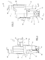
- This device 1 for example as illustrated in figure 4 , is suitable for being mounted on a frame (M) of an automatic machine for cutting leathers.
- the device comprises a body 2 exhibiting an end portion 21; the end portion 21, once the device 1 has been associated to the frame M of the automatic machine, faces towards a leather laid out on a plane, in which leather shapes having various profiles are to be cut.
- the body 2 can be activated in alternating translation, with respect to the frame M of the automatic machine, along a direction Z that is perpendicular to the leather.
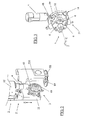
- the cutting device 1 of the present invention exhibits the particularity of further comprising an element 3, in the form of a drum, which exhibits an external peripheral surface 32, and is provided, along the external peripheral surface 32, with a series of housings.
- the drum element 3 is visible in detail, for example, in figures 2 and 3 .
- the element 3 is rotatably mountable on the end portion 21 of the body 2 in such a way that the relative external peripheral surface 32 can rotate about an axis C that is perpendicular to the end portion 21 (see for example figures 1 and 2 ).
- the cutting device 1 of the present invention also exhibits a series of cutting tools 31; each of the cutting tools 31 being provided with a respective cutting edge having a relative profile that is different from the others, with each cutting tool 31 being mountable in a corresponding housing in the series of housings present in the external peripheral surface 32 of the drum element 3 such that the relative cutting edges are facing in an external direction.
- a specific peculiarity of the device 1 of the invention consists in the fact that the drum-shaped element 3 is activatable in rotation about the axis C with respect to the end portion 21 of the body 2 such that a single cutting tool 31 at a time can be positionable facing the leather and the cutting edge thereof faces towards the leather in which a shape is to be cut.
- the device of the invention it is possible to select the correct cutting tool 31 rapidly and simply and without having recourse to halting the machine, i.e. the tool having a cutting edge with the profile corresponding to the shape which is to be realised in the leather.
- the device 1 exhibits a first actuator means 4, for example constituted by an encoder motor, which can be commanded, according to the profile desired for the shape to be cut in the leather, such as to activate the drum-shaped element 3 in rotation about the axis C with respect to the end portion 21 of the body 2 such as to bring one of the cutting tools 31 mounted on the element 3, having a corresponding desired profile for the shape to be cut, to face the leather and have the relative cutting edge positioned towards the leather.
- a first actuator means 4 for example constituted by an encoder motor, which can be commanded, according to the profile desired for the shape to be cut in the leather, such as to activate the drum-shaped element 3 in rotation about the axis C with respect to the end portion 21 of the body 2 such as to bring one of the cutting tools 31 mounted on the element 3, having a corresponding desired profile for the shape to be cut, to face the leather and have the relative cutting edge positioned towards the leather.
- the first actuator means 4 (encoder motor) is advantageously connectable to the control and management unit which is usually comprised in automatic machines for cutting shapes in the leathers, in which control and management unit the various profiles of the different shapes to be cut in the leathers are memorised.
- the first actuator means 4 can be commandable in real time such as to activate the rotation of the drum-shaped element 3 such that it can be set in rotation about the axis C up to positioning a desired cutting tool 31 in front of the leather in which the shape is to be cut. Once the desired cutting tool 31 has reached the position in front of the leather to be cut, the first actuator means 4 is deactivated and the rotation of the drum 3 halted.
- the end portion 21 of the body 2 in the embodiment of the device illustrated in the accompanying figures of the drawings, and as clearly visible for example in figure 1 , exhibits a fork shape having a pair of arms 22, 220 flanked to and distanced from one another.
- the drum-shaped element 3 is mountable between the pair of arms 22, 202 and the first actuator organ 4, responsible for the rotating activation of the drum-shaped element 3, is predisposed internally of a first arm 220 of the pair of arms 22.
- the first arm 220 of the pair of arms 20, 220 is mounted, with respect to the body 2, in such a way as to be removable from the body 2 (a situation for example illustrated in figure 2 ).
- the device 1 For the transmission of the rotating motion to the drum-shaped element 3, the device 1 comprises a pinion 48 mounted on the axis of the first actuator organ 4 and activatable in rotation thereby, and a cogged crown wheel 49, which is directly mounted on the drum-shaped element 3.
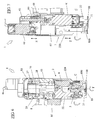
- the pinion 48 couples to and enmeshes with the cogged crown wheel 49 (see for example figures 2 and 3 ) in order to enable transmission of the rotation from the first actuator means 4 to the drum-shaped element 3.
- the cutting tools 31, which can be predisposed and mounted in the housings of the drum-shaped element 3, can comprise a relative closed-profile cutting edge, or a relative open-profile cutting edge, or both, and the cutting tools are usually internally hollow.
- the device 1 of the invention can advantageously exhibit a drum-shaped element 3 that is provided with a series of conduits 6 for passage of compressed air, with each of the conduits 6 leading respectively to each of the support housings of the cutting tools T, and, consequently, leading to the hollow internal part of the cutting tools 31 (see in particular figure 3 ).
- the device 1 can exhibit, internally of the end portion 21 of the body 2, a channel communicating with a source of compressed air, the communicating channel being connectable with a conduit 6 of the conduits 6 when a cutting tool 31 borne by the relative housing into which the conduit 6 leads is brought into a position with the relative cutting edge facing towards the leather in which a corresponding shape is to be cut, following the rotation of the drum-shaped element 3 about the axis C.
- compressed air can be injected into the communication channel, with the compressed air being thus conveyed into the hollow internal part of the cutting tool, reaching the end thereof in order to push the portion of cut leather, which is circumscribed internally of the relative cutting edge, to detach therefrom.
- the device 1 comprises a structure 1 that supports the body 2 and further comprises second actuator means 41 (for example also constituted by an encoder motor connectable to the management and control unit present in the automatic machine to which the device is mounted) which are commandable in such a way as to be able to set the structure 60 in alternative translation, and thus the body 2 with the relative end portion 21 and the drum element 3, with the relative cutting tools 31, along the direction Z perpendicular to the leather in which the shapes are to be realised (see for example figure 1 or figure 7 ).
- second actuator means 41 for example also constituted by an encoder motor connectable to the management and control unit present in the automatic machine to which the device is mounted
- the second actuator means 41 is mounted and borne by a flange 8 which is fixable to the frame M of the automatic machine for cutting leathers on which the cutting device of the invention is to be used.
- the structure 60 in the embodiment of the device illustrated in the accompanying figures of the drawings, comprises a plate 61, provided with an axial hole, and a threaded ring nut 63 which is fixed to the plate 61 coaxially to the through-hole.
- a screw 42 is insertable and rotatable in the through-hole and the threaded ring nut 63, the screw 42 being commandable in rotation by the second actuator means 41.
- the structure 60 further comprises a cylindrical portion 65 borne by the plate 61, the cylindrical portion 65 being internally hollow and exhibiting a shape that is such as to be able to receive and support, internally thereof, a central part 28 of the body 2, the body 2 being mountable with the central part 28 thereof in the cylindrical portion 65, in such a way as to be set in rotation with respect to the cylindrical portion 65, with the relative end portion 21 and the drum-shaped element 3 mounted thereon, about a rotation axis T which is parallel to the alternative translation direction Z of the body 2, and perpendicular to the rotation axis C of the drum-shaped element 3 (see for example figure 1 and figure 6 ).
- the device 1 comprises a third actuator meansorgan 68 (which can also be for example constituted by an encoder motor connectable to the control and management unit of the automatic machine) mounted on the platne 61 and being commandable such as to set the body 2 in rotation with respect to the cylindrical portion 65 about the rotation axis T.
- a third actuator meansorgan 68 (which can also be for example constituted by an encoder motor connectable to the control and management unit of the automatic machine) mounted on the platne 61 and being commandable such as to set the body 2 in rotation with respect to the cylindrical portion 65 about the rotation axis T.
- the cutting device 1 comprises a pulley 70 which is mounted on the body 2 at a relative end portion 27 thereof, opposite the end portion 21, and a belt 29, which winds on the pulley 70, which belt 29 is activatable by the third actuator means 68 such as to activate the rotation of the body 2 about the rotation axis T.
- a casing 80 is provided, which is couplable to the structure 60 for covering and protecting the screw 42, pulley 70, belt 29 and end portion 27 of the body 2.
- the cutting device 1 is further provided with a flat abutting element 88 of the leather; the flat element 88 is mounted relatively translatingly, by means of an interposing of compressible elastic organs 880 (for example springs), to the external end of the end portion 21.
- compressible elastic organs 880 for example springs
- the flat element 88 exhibits a through-slot 89 for enabling free passage of the cutting edge of one of the tools 31 when the cutting edge is positioned facing the leather following the rotation of the drum-shaped elements 3.
- the first actuating means 4 is commanded to set the drum element 3 in rotation about the axis C up to when the cutting tool 31 mounted thereon, having the appropriate cutting edge, is positioned facing and turned towards the leather.
- the third actuating means 68 is then commanded such as to set the screw 41 in rotation, and consequently to set the plate 61 of the structure 60, and therefore the body 2 of the device 1, to translate according to the direction Z towards the leather up to when the flat element 88 contacts with and rests against the surface of the leather.
- the third actuator means 68 is however commanded to continue to translate the body 2 towards the leather, which determines a compression of the elastic organs 880, up to when the cutting edge of the cutting tool 31 inserts in the slot 89 present in the flat element 88 and passes through the leather by cutting a shape in it.
- compressed air can be supplied internally of the communicating channel which is connected with the conduit 6 which, by means of the hollow internal part of the cutting tool, reaches up to the end thereof.
- the cutting device 1 can be fixable, by means of the flange 8, to a frame M of an automatic machine for cutting profiles in leathers.
- the frame M which is mobile with respect to the plane on which the leather is laid out, can be activatable such as to bring the cutting device 1 to one or more positions in which one or more shapes exhibiting profiles that are different to one another are to be cut.
- the first actuator means 4 can be activatable such as to rotate the drum-shaped element 3 in order for the cutting tool 31, having the cutting edge with the profile corresponding to the profile of the shape which is to be cut in the leather, to be positioned facing towards the leather.
- the third actuating means 68 can be commandable to impose on the body 2, via the rotation of the screw 42 in the above-described ways, a translation along the direction Z perpendicularly towards the leather up to when the cutting edge of the tool has passed beyond the leather, cutting therein a corresponding shape.
- the second actuator means 68 can be commandable such as to set the body 2, by means of the rotation of the pulley 70, in rotation about the axis T such as to angularly orientate the cutting edge of the cutting tool 31 with respect to the leather, in the orientation desired for the shape to be obtained.
Landscapes
- Engineering & Computer Science (AREA)
- Mechanical Engineering (AREA)
- Life Sciences & Earth Sciences (AREA)
- Forests & Forestry (AREA)
- Chemical & Material Sciences (AREA)
- Organic Chemistry (AREA)
- Treatment And Processing Of Natural Fur Or Leather (AREA)
- Treatment Of Fiber Materials (AREA)
Priority Applications (1)
| Application Number | Priority Date | Filing Date | Title |
|---|---|---|---|
| PL11187900T PL2453025T3 (pl) | 2010-11-10 | 2011-11-04 | Urządzenie tnące do wycinania kształtów w skórach |
Applications Claiming Priority (1)
| Application Number | Priority Date | Filing Date | Title |
|---|---|---|---|
| ITBO2010A000678A IT1402819B1 (it) | 2010-11-10 | 2010-11-10 | Dispositivo per il taglio di sagome in pelli |
Publications (2)
| Publication Number | Publication Date |
|---|---|
| EP2453025A1 true EP2453025A1 (de) | 2012-05-16 |
| EP2453025B1 EP2453025B1 (de) | 2013-06-19 |
Family
ID=43742538
Family Applications (1)
| Application Number | Title | Priority Date | Filing Date |
|---|---|---|---|
| EP11187900.3A Not-in-force EP2453025B1 (de) | 2010-11-10 | 2011-11-04 | Eine Schneidvorrichtung zum Schneiden Formen in Leder |
Country Status (6)
| Country | Link |
|---|---|
| EP (1) | EP2453025B1 (de) |
| BR (1) | BRPI1106254A2 (de) |
| ES (1) | ES2425636T3 (de) |
| IT (1) | IT1402819B1 (de) |
| MX (1) | MX343164B (de) |
| PL (1) | PL2453025T3 (de) |
Cited By (2)
| Publication number | Priority date | Publication date | Assignee | Title |
|---|---|---|---|---|
| IT201700068522A1 (it) * | 2017-06-20 | 2018-12-20 | Officina Mecc Bibo Srl | Dispositivo per la movimentazione di stampi atti alla realizzazione di timbrature localizzate e alternative |
| CN117255863A (zh) * | 2021-03-11 | 2023-12-19 | 特西奥股份公司 | 用于皮革薄片切割机的具有振动叶片的气动切割装置 |
Families Citing this family (3)
| Publication number | Priority date | Publication date | Assignee | Title |
|---|---|---|---|---|
| CN108326951A (zh) * | 2017-01-20 | 2018-07-27 | 启翔股份有限公司 | 自动切换冲头装置 |
| CN110883854B (zh) * | 2019-11-29 | 2021-01-29 | 福建榕丰塑胶有限公司 | 一种一次性餐盒模具加工用开孔装置 |
| CN111545641B (zh) * | 2020-04-26 | 2021-09-21 | 合肥众机群机械制造有限公司 | 一种吊耳加工用冲弯曲装置 |
Citations (6)
| Publication number | Priority date | Publication date | Assignee | Title |
|---|---|---|---|---|
| US1407769A (en) * | 1921-05-18 | 1922-02-28 | Premo Alexander | Numbering, forming and cutting die |
| GB479365A (en) * | 1935-08-22 | 1938-02-04 | Tubular Perforating And Machin | Improvements in perforating machines |
| GB611446A (en) * | 1946-04-30 | 1948-10-29 | Harry Vernon Fox | Improvements in or appertaining to piercing or punching tools |
| AU9040882A (en) * | 1981-11-26 | 1983-07-28 | Milham, W.R. | Jig for plier punch |
| EP0875310A1 (de) * | 1997-05-01 | 1998-11-04 | Euromac S.r.l. | Revolver zum Werkzeugwechsel in Stanzpressen |
| US20080314220A1 (en) * | 2007-06-21 | 2008-12-25 | Mate Precision Tooling Inc. | Punch press tool for stamping successive multicharacter impressions into a workpiece |
-
2010
- 2010-11-10 IT ITBO2010A000678A patent/IT1402819B1/it active
-
2011
- 2011-11-04 PL PL11187900T patent/PL2453025T3/pl unknown
- 2011-11-04 ES ES11187900T patent/ES2425636T3/es active Active
- 2011-11-04 EP EP11187900.3A patent/EP2453025B1/de not_active Not-in-force
- 2011-11-07 MX MX2011011812A patent/MX343164B/es active IP Right Grant
- 2011-11-10 BR BRPI1106254-1A patent/BRPI1106254A2/pt not_active IP Right Cessation
Patent Citations (6)
| Publication number | Priority date | Publication date | Assignee | Title |
|---|---|---|---|---|
| US1407769A (en) * | 1921-05-18 | 1922-02-28 | Premo Alexander | Numbering, forming and cutting die |
| GB479365A (en) * | 1935-08-22 | 1938-02-04 | Tubular Perforating And Machin | Improvements in perforating machines |
| GB611446A (en) * | 1946-04-30 | 1948-10-29 | Harry Vernon Fox | Improvements in or appertaining to piercing or punching tools |
| AU9040882A (en) * | 1981-11-26 | 1983-07-28 | Milham, W.R. | Jig for plier punch |
| EP0875310A1 (de) * | 1997-05-01 | 1998-11-04 | Euromac S.r.l. | Revolver zum Werkzeugwechsel in Stanzpressen |
| US20080314220A1 (en) * | 2007-06-21 | 2008-12-25 | Mate Precision Tooling Inc. | Punch press tool for stamping successive multicharacter impressions into a workpiece |
Cited By (2)
| Publication number | Priority date | Publication date | Assignee | Title |
|---|---|---|---|---|
| IT201700068522A1 (it) * | 2017-06-20 | 2018-12-20 | Officina Mecc Bibo Srl | Dispositivo per la movimentazione di stampi atti alla realizzazione di timbrature localizzate e alternative |
| CN117255863A (zh) * | 2021-03-11 | 2023-12-19 | 特西奥股份公司 | 用于皮革薄片切割机的具有振动叶片的气动切割装置 |
Also Published As
| Publication number | Publication date |
|---|---|
| MX343164B (es) | 2016-10-19 |
| EP2453025B1 (de) | 2013-06-19 |
| ES2425636T3 (es) | 2013-10-16 |
| MX2011011812A (es) | 2014-04-02 |
| ITBO20100678A1 (it) | 2012-05-11 |
| IT1402819B1 (it) | 2013-09-27 |
| BRPI1106254A2 (pt) | 2015-07-28 |
| PL2453025T3 (pl) | 2013-10-31 |
Similar Documents
| Publication | Publication Date | Title |
|---|---|---|
| EP2453025B1 (de) | Eine Schneidvorrichtung zum Schneiden Formen in Leder | |
| US10099293B2 (en) | Equipment with a detachable accessory and assembly for a machining lathe, and machining lathe with digital control | |
| FR2839674A3 (fr) | Scie circulaire munie d'un alignement a laser | |
| EP2402126B1 (de) | Werkzeughaltevorrichtung für Schermaschinen | |
| KR20160074941A (ko) | 밀링 머신의 공작물 가공용 고정치구 | |
| EP2796302B1 (de) | Reifenwulstabdrückvorrichtung für Reifenwechselmaschinen | |
| KR200232774Y1 (ko) | 브이컷팅용 바이트의 연삭부 가공장치 | |
| CN105983929A (zh) | 定位装置 | |
| US20020148339A1 (en) | Trilateral cutter particularly for trimming the edges of books with a simplified blade change | |
| FR2866585A1 (fr) | Procede et dispositif pour la reparation de dentures d'engrenages | |
| CN110900710A (zh) | 一种聚氨酯泡沫塑料裁切机械 | |
| CN216780441U (zh) | 一种用于标准件加工的铣削装置 | |
| CN118578141B (zh) | 一种配电柜加工系统及方法 | |
| CN203789275U (zh) | 自动穿鞋带机 | |
| JP2003181754A (ja) | 通常の研削作業に使用可能な管状加工片切込み成形機 | |
| JP3986828B2 (ja) | ハーフカット装置およびハーフカット方法 | |
| CN218194971U (zh) | 一种截断阀气缸缸盖的专用拆卸、安装工具 | |
| CN203789276U (zh) | 自动穿鞋带机的鞋带拉紧机构 | |
| CN211338069U (zh) | 自动适应工作平台的裁片加工工具、送料装置与压料装置 | |
| EP0580696B1 (de) | Fraeser mit spanbrecher/druckbalken | |
| CN103876395A (zh) | 自动穿鞋带机的鞋帮固定机构 | |
| CN114433676B (zh) | 一种用于折弯机压刀的一体式拆卸调节装置 | |
| CN208604140U (zh) | 一种多刀旋转冲孔装置 | |
| KR20090079675A (ko) | 타이어 금형의 에어밴팅홀 천공장치 | |
| KR102105438B1 (ko) | 전단기 |
Legal Events
| Date | Code | Title | Description |
|---|---|---|---|
| PUAI | Public reference made under article 153(3) epc to a published international application that has entered the european phase |
Free format text: ORIGINAL CODE: 0009012 |
|
| AK | Designated contracting states |
Kind code of ref document: A1 Designated state(s): AL AT BE BG CH CY CZ DE DK EE ES FI FR GB GR HR HU IE IS IT LI LT LU LV MC MK MT NL NO PL PT RO RS SE SI SK SM TR |
|
| AX | Request for extension of the european patent |
Extension state: BA ME |
|
| 17P | Request for examination filed |
Effective date: 20121018 |
|
| RIC1 | Information provided on ipc code assigned before grant |
Ipc: B26F 1/04 20060101ALI20121116BHEP Ipc: B21D 28/36 20060101ALI20121116BHEP Ipc: C14B 5/00 20060101AFI20121116BHEP |
|
| REG | Reference to a national code |
Ref country code: DE Ref legal event code: R079 Ref document number: 602011002072 Country of ref document: DE Free format text: PREVIOUS MAIN CLASS: C14B0005000000 Ipc: B26D0005080000 |
|
| GRAP | Despatch of communication of intention to grant a patent |
Free format text: ORIGINAL CODE: EPIDOSNIGR1 |
|
| RIC1 | Information provided on ipc code assigned before grant |
Ipc: C14B 5/00 20060101ALI20130110BHEP Ipc: B26F 1/04 20060101ALI20130110BHEP Ipc: B26D 5/08 20060101AFI20130110BHEP Ipc: B21D 28/36 20060101ALI20130110BHEP |
|
| GRAS | Grant fee paid |
Free format text: ORIGINAL CODE: EPIDOSNIGR3 |
|
| GRAA | (expected) grant |
Free format text: ORIGINAL CODE: 0009210 |
|
| AK | Designated contracting states |
Kind code of ref document: B1 Designated state(s): AL AT BE BG CH CY CZ DE DK EE ES FI FR GB GR HR HU IE IS IT LI LT LU LV MC MK MT NL NO PL PT RO RS SE SI SK SM TR |
|
| REG | Reference to a national code |
Ref country code: GB Ref legal event code: FG4D |
|
| REG | Reference to a national code |
Ref country code: CH Ref legal event code: EP |
|
| REG | Reference to a national code |
Ref country code: AT Ref legal event code: REF Ref document number: 617385 Country of ref document: AT Kind code of ref document: T Effective date: 20130715 |
|
| REG | Reference to a national code |
Ref country code: IE Ref legal event code: FG4D |
|
| REG | Reference to a national code |
Ref country code: DE Ref legal event code: R096 Ref document number: 602011002072 Country of ref document: DE Effective date: 20130814 |
|
| REG | Reference to a national code |
Ref country code: CH Ref legal event code: NV Representative=s name: RIEDERER HASLER AND PARTNER PATENTANWAELTE AG, LI |
|
| REG | Reference to a national code |
Ref country code: ES Ref legal event code: FG2A Ref document number: 2425636 Country of ref document: ES Kind code of ref document: T3 Effective date: 20131016 |
|
| PG25 | Lapsed in a contracting state [announced via postgrant information from national office to epo] |
Ref country code: GR Free format text: LAPSE BECAUSE OF FAILURE TO SUBMIT A TRANSLATION OF THE DESCRIPTION OR TO PAY THE FEE WITHIN THE PRESCRIBED TIME-LIMIT Effective date: 20130920 Ref country code: SI Free format text: LAPSE BECAUSE OF FAILURE TO SUBMIT A TRANSLATION OF THE DESCRIPTION OR TO PAY THE FEE WITHIN THE PRESCRIBED TIME-LIMIT Effective date: 20130619 Ref country code: LT Free format text: LAPSE BECAUSE OF FAILURE TO SUBMIT A TRANSLATION OF THE DESCRIPTION OR TO PAY THE FEE WITHIN THE PRESCRIBED TIME-LIMIT Effective date: 20130619 Ref country code: FI Free format text: LAPSE BECAUSE OF FAILURE TO SUBMIT A TRANSLATION OF THE DESCRIPTION OR TO PAY THE FEE WITHIN THE PRESCRIBED TIME-LIMIT Effective date: 20130619 Ref country code: NO Free format text: LAPSE BECAUSE OF FAILURE TO SUBMIT A TRANSLATION OF THE DESCRIPTION OR TO PAY THE FEE WITHIN THE PRESCRIBED TIME-LIMIT Effective date: 20130919 Ref country code: SE Free format text: LAPSE BECAUSE OF FAILURE TO SUBMIT A TRANSLATION OF THE DESCRIPTION OR TO PAY THE FEE WITHIN THE PRESCRIBED TIME-LIMIT Effective date: 20130619 |
|
| REG | Reference to a national code |
Ref country code: PL Ref legal event code: T3 |
|
| REG | Reference to a national code |
Ref country code: AT Ref legal event code: MK05 Ref document number: 617385 Country of ref document: AT Kind code of ref document: T Effective date: 20130619 |
|
| REG | Reference to a national code |
Ref country code: LT Ref legal event code: MG4D |
|
| PG25 | Lapsed in a contracting state [announced via postgrant information from national office to epo] |
Ref country code: RS Free format text: LAPSE BECAUSE OF FAILURE TO SUBMIT A TRANSLATION OF THE DESCRIPTION OR TO PAY THE FEE WITHIN THE PRESCRIBED TIME-LIMIT Effective date: 20130619 Ref country code: HR Free format text: LAPSE BECAUSE OF FAILURE TO SUBMIT A TRANSLATION OF THE DESCRIPTION OR TO PAY THE FEE WITHIN THE PRESCRIBED TIME-LIMIT Effective date: 20130619 Ref country code: BG Free format text: LAPSE BECAUSE OF FAILURE TO SUBMIT A TRANSLATION OF THE DESCRIPTION OR TO PAY THE FEE WITHIN THE PRESCRIBED TIME-LIMIT Effective date: 20130919 |
|
| REG | Reference to a national code |
Ref country code: NL Ref legal event code: VDEP Effective date: 20130619 |
|
| PG25 | Lapsed in a contracting state [announced via postgrant information from national office to epo] |
Ref country code: LV Free format text: LAPSE BECAUSE OF FAILURE TO SUBMIT A TRANSLATION OF THE DESCRIPTION OR TO PAY THE FEE WITHIN THE PRESCRIBED TIME-LIMIT Effective date: 20130619 |
|
| PG25 | Lapsed in a contracting state [announced via postgrant information from national office to epo] |
Ref country code: SK Free format text: LAPSE BECAUSE OF FAILURE TO SUBMIT A TRANSLATION OF THE DESCRIPTION OR TO PAY THE FEE WITHIN THE PRESCRIBED TIME-LIMIT Effective date: 20130619 Ref country code: CY Free format text: LAPSE BECAUSE OF FAILURE TO SUBMIT A TRANSLATION OF THE DESCRIPTION OR TO PAY THE FEE WITHIN THE PRESCRIBED TIME-LIMIT Effective date: 20130821 Ref country code: AT Free format text: LAPSE BECAUSE OF FAILURE TO SUBMIT A TRANSLATION OF THE DESCRIPTION OR TO PAY THE FEE WITHIN THE PRESCRIBED TIME-LIMIT Effective date: 20130619 Ref country code: CZ Free format text: LAPSE BECAUSE OF FAILURE TO SUBMIT A TRANSLATION OF THE DESCRIPTION OR TO PAY THE FEE WITHIN THE PRESCRIBED TIME-LIMIT Effective date: 20130619 Ref country code: IS Free format text: LAPSE BECAUSE OF FAILURE TO SUBMIT A TRANSLATION OF THE DESCRIPTION OR TO PAY THE FEE WITHIN THE PRESCRIBED TIME-LIMIT Effective date: 20131019 Ref country code: EE Free format text: LAPSE BECAUSE OF FAILURE TO SUBMIT A TRANSLATION OF THE DESCRIPTION OR TO PAY THE FEE WITHIN THE PRESCRIBED TIME-LIMIT Effective date: 20130619 Ref country code: PT Free format text: LAPSE BECAUSE OF FAILURE TO SUBMIT A TRANSLATION OF THE DESCRIPTION OR TO PAY THE FEE WITHIN THE PRESCRIBED TIME-LIMIT Effective date: 20131021 Ref country code: BE Free format text: LAPSE BECAUSE OF FAILURE TO SUBMIT A TRANSLATION OF THE DESCRIPTION OR TO PAY THE FEE WITHIN THE PRESCRIBED TIME-LIMIT Effective date: 20130619 |
|
| PG25 | Lapsed in a contracting state [announced via postgrant information from national office to epo] |
Ref country code: RO Free format text: LAPSE BECAUSE OF FAILURE TO SUBMIT A TRANSLATION OF THE DESCRIPTION OR TO PAY THE FEE WITHIN THE PRESCRIBED TIME-LIMIT Effective date: 20130619 Ref country code: NL Free format text: LAPSE BECAUSE OF FAILURE TO SUBMIT A TRANSLATION OF THE DESCRIPTION OR TO PAY THE FEE WITHIN THE PRESCRIBED TIME-LIMIT Effective date: 20130619 |
|
| PG25 | Lapsed in a contracting state [announced via postgrant information from national office to epo] |
Ref country code: CY Free format text: LAPSE BECAUSE OF FAILURE TO SUBMIT A TRANSLATION OF THE DESCRIPTION OR TO PAY THE FEE WITHIN THE PRESCRIBED TIME-LIMIT Effective date: 20130619 |
|
| PLBE | No opposition filed within time limit |
Free format text: ORIGINAL CODE: 0009261 |
|
| STAA | Information on the status of an ep patent application or granted ep patent |
Free format text: STATUS: NO OPPOSITION FILED WITHIN TIME LIMIT |
|
| PG25 | Lapsed in a contracting state [announced via postgrant information from national office to epo] |
Ref country code: DK Free format text: LAPSE BECAUSE OF FAILURE TO SUBMIT A TRANSLATION OF THE DESCRIPTION OR TO PAY THE FEE WITHIN THE PRESCRIBED TIME-LIMIT Effective date: 20130619 |
|
| 26N | No opposition filed |
Effective date: 20140320 |
|
| REG | Reference to a national code |
Ref country code: DE Ref legal event code: R097 Ref document number: 602011002072 Country of ref document: DE Effective date: 20140320 |
|
| PG25 | Lapsed in a contracting state [announced via postgrant information from national office to epo] |
Ref country code: MC Free format text: LAPSE BECAUSE OF FAILURE TO SUBMIT A TRANSLATION OF THE DESCRIPTION OR TO PAY THE FEE WITHIN THE PRESCRIBED TIME-LIMIT Effective date: 20130619 |
|
| REG | Reference to a national code |
Ref country code: IE Ref legal event code: MM4A |
|
| PG25 | Lapsed in a contracting state [announced via postgrant information from national office to epo] |
Ref country code: IE Free format text: LAPSE BECAUSE OF NON-PAYMENT OF DUE FEES Effective date: 20131104 |
|
| PG25 | Lapsed in a contracting state [announced via postgrant information from national office to epo] |
Ref country code: SM Free format text: LAPSE BECAUSE OF FAILURE TO SUBMIT A TRANSLATION OF THE DESCRIPTION OR TO PAY THE FEE WITHIN THE PRESCRIBED TIME-LIMIT Effective date: 20130619 |
|
| PG25 | Lapsed in a contracting state [announced via postgrant information from national office to epo] |
Ref country code: TR Free format text: LAPSE BECAUSE OF FAILURE TO SUBMIT A TRANSLATION OF THE DESCRIPTION OR TO PAY THE FEE WITHIN THE PRESCRIBED TIME-LIMIT Effective date: 20130619 |
|
| PG25 | Lapsed in a contracting state [announced via postgrant information from national office to epo] |
Ref country code: MK Free format text: LAPSE BECAUSE OF FAILURE TO SUBMIT A TRANSLATION OF THE DESCRIPTION OR TO PAY THE FEE WITHIN THE PRESCRIBED TIME-LIMIT Effective date: 20130619 Ref country code: HU Free format text: LAPSE BECAUSE OF FAILURE TO SUBMIT A TRANSLATION OF THE DESCRIPTION OR TO PAY THE FEE WITHIN THE PRESCRIBED TIME-LIMIT; INVALID AB INITIO Effective date: 20111104 Ref country code: LU Free format text: LAPSE BECAUSE OF NON-PAYMENT OF DUE FEES Effective date: 20131104 |
|
| PG25 | Lapsed in a contracting state [announced via postgrant information from national office to epo] |
Ref country code: MT Free format text: LAPSE BECAUSE OF FAILURE TO SUBMIT A TRANSLATION OF THE DESCRIPTION OR TO PAY THE FEE WITHIN THE PRESCRIBED TIME-LIMIT Effective date: 20130619 |
|
| REG | Reference to a national code |
Ref country code: FR Ref legal event code: PLFP Year of fee payment: 5 |
|
| REG | Reference to a national code |
Ref country code: DE Ref legal event code: R082 Ref document number: 602011002072 Country of ref document: DE Representative=s name: ELBPATENT-MARSCHALL & PARTNER MBB, DE |
|
| GBPC | Gb: european patent ceased through non-payment of renewal fee |
Effective date: 20151104 |
|
| PG25 | Lapsed in a contracting state [announced via postgrant information from national office to epo] |
Ref country code: GB Free format text: LAPSE BECAUSE OF NON-PAYMENT OF DUE FEES Effective date: 20151104 |
|
| REG | Reference to a national code |
Ref country code: FR Ref legal event code: PLFP Year of fee payment: 6 |
|
| PGFP | Annual fee paid to national office [announced via postgrant information from national office to epo] |
Ref country code: FR Payment date: 20161124 Year of fee payment: 6 |
|
| PGFP | Annual fee paid to national office [announced via postgrant information from national office to epo] |
Ref country code: PL Payment date: 20161007 Year of fee payment: 6 |
|
| PGFP | Annual fee paid to national office [announced via postgrant information from national office to epo] |
Ref country code: DE Payment date: 20171129 Year of fee payment: 7 |
|
| PGFP | Annual fee paid to national office [announced via postgrant information from national office to epo] |
Ref country code: ES Payment date: 20171201 Year of fee payment: 7 |
|
| REG | Reference to a national code |
Ref country code: FR Ref legal event code: ST Effective date: 20180731 |
|
| PG25 | Lapsed in a contracting state [announced via postgrant information from national office to epo] |
Ref country code: FR Free format text: LAPSE BECAUSE OF NON-PAYMENT OF DUE FEES Effective date: 20171130 Ref country code: AL Free format text: LAPSE BECAUSE OF FAILURE TO SUBMIT A TRANSLATION OF THE DESCRIPTION OR TO PAY THE FEE WITHIN THE PRESCRIBED TIME-LIMIT Effective date: 20130619 |
|
| PG25 | Lapsed in a contracting state [announced via postgrant information from national office to epo] |
Ref country code: PL Free format text: LAPSE BECAUSE OF NON-PAYMENT OF DUE FEES Effective date: 20171104 |
|
| REG | Reference to a national code |
Ref country code: DE Ref legal event code: R119 Ref document number: 602011002072 Country of ref document: DE |
|
| PG25 | Lapsed in a contracting state [announced via postgrant information from national office to epo] |
Ref country code: DE Free format text: LAPSE BECAUSE OF NON-PAYMENT OF DUE FEES Effective date: 20190601 |
|
| REG | Reference to a national code |
Ref country code: ES Ref legal event code: FD2A Effective date: 20200102 |
|
| PG25 | Lapsed in a contracting state [announced via postgrant information from national office to epo] |
Ref country code: ES Free format text: LAPSE BECAUSE OF NON-PAYMENT OF DUE FEES Effective date: 20181105 |
|
| PGFP | Annual fee paid to national office [announced via postgrant information from national office to epo] |
Ref country code: IT Payment date: 20211126 Year of fee payment: 11 Ref country code: CH Payment date: 20211129 Year of fee payment: 11 |
|
| P01 | Opt-out of the competence of the unified patent court (upc) registered |
Effective date: 20230327 |
|
| REG | Reference to a national code |
Ref country code: CH Ref legal event code: PL |
|
| PG25 | Lapsed in a contracting state [announced via postgrant information from national office to epo] |
Ref country code: LI Free format text: LAPSE BECAUSE OF NON-PAYMENT OF DUE FEES Effective date: 20221130 Ref country code: CH Free format text: LAPSE BECAUSE OF NON-PAYMENT OF DUE FEES Effective date: 20221130 |
|
| PG25 | Lapsed in a contracting state [announced via postgrant information from national office to epo] |
Ref country code: IT Free format text: LAPSE BECAUSE OF NON-PAYMENT OF DUE FEES Effective date: 20221104 |