EP2453085A2 - Dispositif de verrouillage - Google Patents
Dispositif de verrouillage Download PDFInfo
- Publication number
- EP2453085A2 EP2453085A2 EP20110185169 EP11185169A EP2453085A2 EP 2453085 A2 EP2453085 A2 EP 2453085A2 EP 20110185169 EP20110185169 EP 20110185169 EP 11185169 A EP11185169 A EP 11185169A EP 2453085 A2 EP2453085 A2 EP 2453085A2
- Authority
- EP
- European Patent Office
- Prior art keywords
- control device
- lock cylinder
- primary
- data
- data sequence
- Prior art date
- Legal status (The legal status is an assumption and is not a legal conclusion. Google has not performed a legal analysis and makes no representation as to the accuracy of the status listed.)
- Granted
Links
Images
Classifications
-
- E—FIXED CONSTRUCTIONS
- E05—LOCKS; KEYS; WINDOW OR DOOR FITTINGS; SAFES
- E05B—LOCKS; ACCESSORIES THEREFOR; HANDCUFFS
- E05B47/00—Operating or controlling locks or other fastening devices by electric or magnetic means
- E05B47/06—Controlling mechanically-operated bolts by electro-magnetically-operated detents
- E05B47/0611—Cylinder locks with electromagnetic control
-
- E—FIXED CONSTRUCTIONS
- E05—LOCKS; KEYS; WINDOW OR DOOR FITTINGS; SAFES
- E05B—LOCKS; ACCESSORIES THEREFOR; HANDCUFFS
- E05B15/00—Other details of locks; Parts for engagement by bolts of fastening devices
- E05B15/16—Use of special materials for parts of locks
- E05B15/1614—Use of special materials for parts of locks of hard materials, to prevent drilling
-
- E—FIXED CONSTRUCTIONS
- E05—LOCKS; KEYS; WINDOW OR DOOR FITTINGS; SAFES
- E05B—LOCKS; ACCESSORIES THEREFOR; HANDCUFFS
- E05B47/00—Operating or controlling locks or other fastening devices by electric or magnetic means
- E05B2047/0048—Circuits, feeding, monitoring
- E05B2047/0057—Feeding
- E05B2047/0058—Feeding by batteries
-
- E—FIXED CONSTRUCTIONS
- E05—LOCKS; KEYS; WINDOW OR DOOR FITTINGS; SAFES
- E05B—LOCKS; ACCESSORIES THEREFOR; HANDCUFFS
- E05B47/00—Operating or controlling locks or other fastening devices by electric or magnetic means
- E05B2047/0094—Mechanical aspects of remotely controlled locks
-
- G—PHYSICS
- G07—CHECKING-DEVICES
- G07C—TIME OR ATTENDANCE REGISTERS; REGISTERING OR INDICATING THE WORKING OF MACHINES; GENERATING RANDOM NUMBERS; VOTING OR LOTTERY APPARATUS; ARRANGEMENTS, SYSTEMS OR APPARATUS FOR CHECKING NOT PROVIDED FOR ELSEWHERE
- G07C9/00—Individual registration on entry or exit
- G07C9/30—Individual registration on entry or exit not involving the use of a pass
-
- G—PHYSICS
- G07—CHECKING-DEVICES
- G07C—TIME OR ATTENDANCE REGISTERS; REGISTERING OR INDICATING THE WORKING OF MACHINES; GENERATING RANDOM NUMBERS; VOTING OR LOTTERY APPARATUS; ARRANGEMENTS, SYSTEMS OR APPARATUS FOR CHECKING NOT PROVIDED FOR ELSEWHERE
- G07C9/00—Individual registration on entry or exit
- G07C9/30—Individual registration on entry or exit not involving the use of a pass
- G07C9/32—Individual registration on entry or exit not involving the use of a pass in combination with an identity check
- G07C9/37—Individual registration on entry or exit not involving the use of a pass in combination with an identity check using biometric data, e.g. fingerprints, iris scans or voice recognition
Definitions
- the invention relates to a locking device with a lock cylinder and an actuator for the lock cylinder.
- the lock cylinder has an actuator unit for actuating a closing element, wherein the actuating element has a primary control device provided for controlling the actuator unit, wherein the lock cylinder has a drill protection in an end region facing the actuating element, wherein electrical connection means are provided, the the primary control device with the Connect Actuator and which are performed by the Bohrschutz.
- the arrangement of the actuator unit in the lock cylinder results in a particularly secure configuration, since the actuator unit is thereby prevented from direct access, the i.d.R. From the actuator emanates, is protected. Before the actuator can be manipulated, namely, first the actuator must be removed and overcome the arranged between the actuator and the interior of the lock cylinder Bohrschutz be overcome.
- a secondary control means is provided in the lock cylinder, which is connected via the electrical connection means to the primary control means and adapted to communicate with the primary control means.
- This configuration advantageously allows direct actuation of the actuator unit by the secondary control device, which is likewise arranged in a protected manner in the interior of the lock cylinder, while an operation of the secondary control device can be controlled, for example, by the primary control device.
- a corresponding exchange of data between the control devices can take place via the electrical connection means, which can preferably also provide a coding or encryption of exchanged information.
- the primary control device is designed to receive information, in particular control commands and / or identification data, from an identification transmitter via an interface unit and to transmit data to the secondary control device as a function of the received information.
- the data exchange with the information transmitter can preferably take place wirelessly, for example via a suitable radio protocol or using an RFID system, in which the interface unit has an RFID reader, and in which the information transmitter in a conventional manner via at least one RFID transponder has, store the identification data and can send when requested by the RFID reader to this.
- the interface unit may alternatively or additionally have means for inputting biometric data (fingerprints, retina / iris structures, DNA data).
- biometric data fingerprints, retina / iris structures, DNA data.
- a contact-bound electronic transmission for example by means of radio-frequency signals emitted by the identification transmitter, which propagate over the body surface of a person touching the actuating element, is likewise conceivable.
- the primary control device is designed to forward the signals received by the interface unit from the identification transmitter via the electrical connection means to the secondary control device.
- the primary control device may be relatively simple, because it has to forward substantially only the received signals, while an evaluation of the received signals and possibly subsequent control of the actuator by the arranged in the lock cylinder secondary control device takes place.
- the primary control device can therefore be made passive, ie even serve only to establish an electrical connection between the interface unit and the electrical connection means leading to the secondary control device.
- An authorization check and / or other analysis of the data received from the interface unit can preferably be carried out by the secondary control device in this variant.
- the primary control device may also be designed to amplify the signals received by the interface unit from the identification transmitter and / or to shape them with respect to their frequency spectrum (filtering) and / or to demodulate and / or to to modulate, for example, to ensure a secure data transfer to the secondary control device carrying out a further signal processing or evaluation.
- the primary control device is designed to subject received identification data to an authorization check, and to transmit the positive result of the authorization check signaling control information to the secondary control device in the case of a positive result of the authorization check.
- the authorization check can, for example, have a comparison with the subject it is determined whether the received identification data with stored in the primary and / or secondary control device identification data, for example, represent authorized users of the locking device, match.
- corresponding data communication between the control devices can accordingly take place.
- the authorized users assigned identification data are stored in a memory assigned to the primary control device, which memory may preferably also be integrated in the primary control device. If the primary control device has, for example, a microcontroller, the identification data associated with the authorized users can be stored in a nonvolatile memory of the microcontroller.
- the authorization check can take place solely in the primary control device, so that for this purpose no resources in the secondary control device and for data communication between the two control devices are to be reserved. Only the control information indicating the positive result of the authorization check is transmitted to the secondary control device after the evaluation in the primary control device. The secondary control device can then advantageously directly control the actuator unit, for example, to unlock a closing member of the lock cylinder.
- the actuator unit can act in a conventional manner directly on a closing member of the lock cylinder.
- the actuator For example, to form rotatable relative to the lock cylinder, and to provide a mechanical coupling between the actuator and the closing member, said mechanical coupling is interruptible by arranged between the actuator and the closing member coupling means, for example, as long as no proper identification signal has been sent to the interface unit.
- the actuator unit thus does not act directly on the closing member, but on the coupling means to control a mechanical coupling between the actuating element and closing member. This has the advantage that an actuating force for the drive of the closing member must be applied by a person using the locking device, and not by an actuator of the actuator unit.
- the secondary control device is designed to transmit at least one data sequence to the primary control device after receipt of the control information indicating the positive result of the authorization check, the data sequence being transmitted from the primary control device for future communication with the secondary control device is usable.
- the data sequence preferably represents secret information that is known only to the two controllers and thus can be used to verify future data communications between the two controllers.
- the secondary control device can also be used at other, generally arbitrary, times send several data sequences to the primary controller to ensure that they always have a sufficient supply of data sequences.
- the secondary control device is designed to form the data sequence as a function of a random process and / or a quasi-random process, wherein the control devices are designed to store the at least one data sequence in each case in a volatile memory.
- both control devices each have at least one non-volatile, identical data sequence for initialization, so that a first signaling from the primary control device to the secondary control device can also be recognized as a proper communication process.
- This initialization sequence can be used eg after a battery change.
- the initialization sequence is preferably written in the manufacture of the locking device in the memory of the two control devices, wherein for each copy of the locking device 100, in turn, another value is used.
- the initialization sequence is preferably written into an internal EEPROM memory of the relevant microcontroller. The initialization sequence thus becomes a "pairing" process allows the first communication of the control devices with each other. For further, future communications, preferably dynamically generated data sequences are used.
- a reset mechanism can also be provided in a further advantageous embodiment of the invention, which is preferably accessible only after disassembly of the closing device and memorizing a new initialization sequence eg in the control device (s) allows.
- a default value for the initialization sequence can be transmitted once via the interface, e.g. from a special information provider, and that it stores this for future operation.
- This default value may e.g. be forwarded to the secondary controller, which is also configured so that it receives the default value once via the cable connection and non-volatile stores.
- the primary control device is designed to form the control information signaling the positive result of the authorization check as a function of at least one data sequence previously received by the secondary control device.
- the control information may also be identical to the data sequence. Since the data sequence has previously been formed and stored by the secondary controller, the secondary controller may receive upon receipt of a corresponding one of them Data sequence or data derived therefrom recognize that the primary control device or its data communication to the secondary control device, has not been manipulated. Only then can the secondary control device control, for example, the actuator unit.
- a clamping device is provided in the lock cylinder, which is designed to apply at least one component of the electrical connection means, in particular at least one electrical connection cable, with a tensile force.
- the tensioning device can have, for example, a spring device.
- the tensile force with which the tensioning device acts on the connection cable is chosen so that a proper connection of the connection cable to the primary control device is not impaired, that in a mechanical interruption of the connection cable, as may occur in a sabotage attempt, but this, preferably completely , is pulled through the drilling protection into an inner region of the lock cylinder.
- an unauthorized person advantageously takes the opportunity to supply the actuator unit with signals or electrical energy for activation.
- the embodiment described above may also be provided in such closing devices, which have a secondary control device in the lock cylinder.
- the tensioning device is then arranged between the drilling protection and the secondary control device.
- an electrical and / or mechanical contacting of at least one component of the electrical connection means with a contact point in the region of the lock cylinder is so designed such that at least the electrical contact of the component opens to the contact point when the component is subjected to a tensile force which is greater than a holding force of the entire connector, in particular greater than about 1 Newton per plug contact.
- the contact point may be formed, for example, as a socket in which one end of a cable of the electrical connection means or a corresponding plug is held non-positively, for example by means of electrically conductive spring means.
- a tensile force which is too great in relation to the design of the system, acts on the cable, at least the electrical connection between the contact point and the cable breaks off, so that controlled control of components integrated in the lock cylinder can no longer take place via the cable.
- Too high a tensile force for example, a force of about 1 Newton per plug contact of the connector can be defined.
- the length of the connecting cable and / or the frictional connection in the contact point and / or the arrangement of the contact point and / or the leadership of the connecting cable in the lock cylinder connecting cable are to match as closely as possible.
- the force required for tearing off the electrical connection between the contact point and the cable can be adjusted within wide limits.
- the electrical connection means comprise a plurality of individual conductors, wherein at least some conductors are formed from enameled copper wire.
- the electrical connection means comprise at least one frangible electrical conductor, which in a manipulation attempt causes the targeted interruption of the electrical connection between the actuating element or the components arranged therein and the interior of the lock cylinder.
- the destruction of such a portion of the fragile conductor which is arranged in the interior of the lock cylinder, in particular behind the drilling protection, so that the deliberately induced interruption point is accessible from the side of the actuating element only by overcoming the Bohrschutzes.
- an actuator is provided in the actuating element, which is designed to unlock under control by the primary control means a locking mechanism, wherein the locking mechanism is provided to complicate an unauthorized opening of a housing of the actuating element or to prevent.
- the actuator can be designed so that it moves out a pin from a locking position when it is actuated, in which the bolt locks a first housing part (eg grip area) of the actuating element with a second housing part (eg cover) of the actuating element.
- the activation of the actuator can be effected, for example, by the primary control device and triggered, for example, after the reception of an identification signal of a special transponder.
- a secondary control device arranged in the lock cylinder transmits at least one data sequence to the primary control device, wherein the primary control device and the secondary control device store the data sequence in a volatile memory, and wherein the primary control device stores the stored data Data sequence and / or data sequence dependent information to the secondary controller sends.
- the data sequence which is initially generated by the secondary control device, preferably at random, serves as a so-called "shared secret" of the two control devices, which they can use for future communication, whereby this communication can be protected against manipulation attempts. Since no valid data communications between the controllers can be established without knowledge of the secret data sequences, it is impossible for unauthorized persons, e.g. to simulate the primary control device and to cause in this way the secondary control device for controlling the actuator unit.
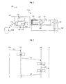
- FIG. 1 a schematically shows a first embodiment of a closing device 100 according to the invention, which has a locking cylinder 110 and an actuating element 120 embodied here as a rotary knob.
- a not separately designated housing of the lock cylinder 110 may be formed, for example, in the manner of a DIN profile cylinder or other standard lock cylinder, so that the locking device 100, for example, instead of conventional lock cylinder in mortise locks of doors and the like can be used.
- FIG. 1 shows a configuration which is referred to as "solid cylinder", the invention described below Principle also be applied to half-cylinder, which offer a closing / opening a door (not shown) only from one side.
- the actuator 120 has a primary controller 122 which is connected via electrical connection means 130, e.g. a multi-core cable, is connected to a arranged in the lock cylinder 110 secondary controller 118 and can exchange data with this.
- electrical connection means 130 e.g. a multi-core cable
- the data exchange between the controllers 122, 118 is bidirectional.
- the secondary controller 118 is connected to an actuator unit 114 and may drive it in response to control commands communicated to the secondary controller 118 by the primary controller 122 via the cable 130.
- the actuator unit 114 acts on a closing member 112 of the lock cylinder, for example, with a locking bolt (not shown) of a door, in which the lock cylinder 110 is installed, cooperates in a conventional manner to close the door.
- the lock cylinder 110 In its end region 110a facing the actuating element 120, the lock cylinder 110 has a drill guide 116 which is preferably approximately bell-shaped and prevents or at least complicates the boring of the lock cylinder 110 and other manipulations in the end region 110a.
- the cable 130 is passed through an opening in the drill guide 116.
- FIG. 1 just one represents schematic drawing in which, for example, the passage opening for the cable 130 in the drilling protection 116 is significantly larger than technically required indicated in the drawing.
- the electrical energy supply of the components 114, 118, 122 is accomplished by means of an electric energy source 124 integrated in the knob 120, in which case it may, for example, be a battery.
- an electric energy source 124 integrated in the knob 120, in which case it may, for example, be a battery.
- the cable 130 may also be used.
- the primary control device 122 has an interface unit 122a and is configured to receive information, in particular control commands and / or identification data, from an identification transmitter 122b via the interface unit 122a and to transmit data to the secondary control device 118 as a function of the received information. In this way, e.g. Control commands for opening and closing the closing device 100 are transmitted from the identification transmitter 122b via the primary control device 122 to the secondary control device 118 in the interior of the lock cylinder 110.
- the interface unit 122a may comprise, for example, an RFID (radio frequency identification) reading unit which cooperates with a RFID transponder arranged in the identification transmitter 122b in a manner known per se in order to transmit information from a memory of the RFID transponder to the control device 122.
- the interface unit 122a may be another wireless or wired data transfer or exchange biometric data (eg fingerprints, retina / iris structures, DNA data).
- the primary controller 122 can be made relatively simple because it essentially only has to relay the signals received from the RFID transponder, while an evaluation of the received signals and the possible subsequent activation of the actuator unit 144 e.g. is performed by arranged in the lock cylinder 110 secondary control device 118.
- the primary control device 122 may therefore even be passive, if necessary even serve only to establish an electrical connection between the interface unit 122a and the cable 130 leading to the secondary control device 118.
- the primary control device 122 may also be designed to amplify the signals received by the interface unit 122a from the identification transmitter 122b and / or to shape them with respect to their frequency spectrum (filtering) and / or to demodulate and / or to modulate, for example, to ensure a secure and reliable data transmission to the secondary control device 118 which carries out further signal processing or evaluation.
- the primary control device 122 is configured to subject received identification data to an authorization check, and in the case of a positive result of the authorization check, the positive result of the authorization check Authorization check signaling control information to the secondary controller 118 to transmit. Accordingly, a first evaluation of the received signals or data in the primary control device 122 already takes place in this variant of the invention.
- the authorization check can for example be based on a comparison in which it is determined whether the received identification data is present in the primary and / or secondary control device 122, 118 deposited identification data, for example, representing authorized users of the locking device match. Depending on the storage location of the stored identification data (primary / secondary control device), corresponding data communication between the control devices can accordingly take place.
- the identification data assigned to the authorized users are stored in a memory 122c assigned to the primary control device 122.
- the primary controller 122 may include a microcontroller, and the identification data associated with the authorized users may be stored in a nonvolatile memory 122c of the microcontroller.
- the authorization check can advantageously take place solely in the primary control device 122, so that no resources are to be reserved in the secondary control device 188 and for data communication between the two control devices 118, 122 for this purpose. Only the control information indicating the positive result of the authorization check is transmitted to the secondary control device 118 after the evaluation by the primary control device 122.
- the secondary control device 122 can then advantageously directly control the actuator unit 114, for example, the Closing member 112 of the lock cylinder 110 to unlock or to move between different possible operating conditions.
- FIG. 2 shows by way of example a communication diagram indicating a data flow between the components 122b, 122, 118, 114 during an identification process according to the invention.
- the identification transmitter 122b sends an identification signal s_2 to the primary control device 122, which receives the identification signal s_2 via its interface 122a.
- step 200 the primary controller 122 checks to see if the received identification signal s_2 is a known identification signal s_2, e.g. an authorized user of the closing device 100 is assigned. For this purpose, a search operation can be performed via the memory 122c.
- the primary control device 122 sends an enable signal s_4 via the connection cable 130 (FIG. FIG. 1 ) to the secondary controller 118.
- the secondary control device 118 evaluates the enable signal s_4 and finally activates, by means of the signal s 6, the actuator unit 114 in a manner corresponding to the enable signal s_4, for example in order to unlock the closing element 112.
- the actuator unit 114 which may be e.g. An electromagnetic actuator (e.g., solenoid or electric motor) may act directly on the closure member 112 of the lock cylinder 110 in a manner known per se.
- An electromagnetic actuator e.g., solenoid or electric motor
- the actuator 120 may be deactivated, and only if a successful identification process, cf. FIG.
- the coupling means are driven in a second mode by the actuator unit 114 for a predetermined period of time to enable the coupling between the knob 120 and the closing member 112, so that an authorized person by turning the knob 120, the closing device 100 can open ,
- the Data sequence preferably represents secret information which is known only to the two controllers 118, 122 and thus can be used to verify future data communications between the two controllers 118, 122.
- the secondary control device 118 is designed to form the data sequence (s) as a function of a random process and / or a quasi-random process.
- the secondary control device 118 which may also have a microcontroller analogous to the primary control device 122, after the receipt of the enable signal s_4 from the primary control device 122, form one or more data sequences, cf. Step 220 off FIG. 2 , Subsequently, the secondary controller 118 may transmit the data sequence (s) to the primary controller 122, cf. Signal s_8.
- the controllers 118, 122 are preferably configured to store the data sequence (s) in a volatile memory, e.g. in a random access memory (RAM) of the respective microcontroller to store.
- a volatile memory e.g. in a random access memory (RAM) of the respective microcontroller to store.
- the data sequences generated in the course of the operation of the locking device 100 are individual and change continuously, ie from sequence to sequence, so that the greatest possible security against manipulation is given. In this way, it is advantageously prevented, for example, that an unauthorized person forcibly separates the knob 120 from the lock cylinder 110 and successfully sends control commands via the then exposed cable 130 to the secondary controller 118.
- the secondary control device 118 can also send one or more data sequences to the primary control device 122 at other, generally arbitrary, times to ensure that they always have a sufficient supply of data sequences features.
- the control information or the enable signal s_4 can also be identical to a data sequence, for example. Since the data sequence has previously been formed by the secondary controller 118 and stored, preferably volatile, upon receipt of a corresponding data sequence or data derived therefrom, the secondary controller 118 may recognize that the primary controller 122 or its data communication to the secondary controller 118 , has not been manipulated because the data sequences are known only to the two components 118, 122. Only then can the secondary control device 118 control, for example, the actuator unit.
- random-based data sequences may consist of an electronic noise signal which is applied to an A / D (analog / digital) converter input of a microcontroller 118a (FIG. FIG. 1 ) of the secondary controller 118, or from a value of a timer register of the microcontroller 118a.
- Quasi random numbers can be determined in a manner known per se by means of a suitable software program for the microcontroller.
- both control devices 118, 122 each have at least one non-volatile, identical data sequence for initialization, so that a first signaling from the primary control device 122 to the secondary control device 118 can be recognized as a proper communication process.
- This initialization sequence can be e.g. be used after a battery change.
- the initialization sequence is preferably written in the manufacture of the locking device 100 in the memory of the two controllers 118, 122, wherein for each copy of the locking device 100 in turn another value is used.
- the initialization sequence is preferably written into an internal EEPROM memory of the relevant microcontroller.
- the initialization sequence is only used for communication between the control devices 118, 122 if a correspondingly coded key has previously been recognized via the interface 122a.
- the coded key can For example, it may be a type of "master" transponder 122b that is authorized to initiate the use of the initialization sequence.
- the primary control device 122 can be used to transmit a default value for the initialization sequence via the interface 122a once, e.g. from a special information provider, and that it stores this for future operation.
- This default value may e.g. also be forwarded to the secondary controller 118, which is also configured to receive the default value once via the cable connection 130 and non-volatile stores.
- a reset mechanism for programming an initialization sequence can be provided, which is accessible, for example, only after a legitimate opening of the lock cylinder 110 and allows the reprogramming of an initialization sequence.
- individual components of the closing device 100 can also advantageously be exchanged subsequently.
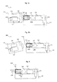
- FIG. 3a shows a further embodiment 100a of a locking device according to the present invention in a first operating state.
- a clamping device 140 is provided which is adapted to at least one component of the electric cable 130, in particular at least one wire of the cable 130, to apply a tensile force, see. the block arrow in the clamping device 140.
- the clamping device 140th for example, have a spring device not shown.
- the tensile force with which the tensioning device 140 acts on the connecting cable 130 or individual wires thereof is selected such that a proper connection of the connecting cable 130 to the primary control device 122 is not impaired, that with a mechanical interruption of the connecting cable 130, as in a tampering attempt, the cable 130, preferably completely, is pulled through the drill guide 116 into a protected inner area 110b of the lock cylinder 110.
- an unauthorized person advantageously takes the opportunity to supply the actuator unit 114 with signals or electrical energy for activation.
- FIG. 3b shows the locking device 100a according to FIG. 3a in a damaged state due to a manipulation attempt.
- the knob 120 has been mechanically separated from the lock cylinder 110.
- the tensioning means 140 have advantageously retracted the cable 130 also severed during the manipulation attempt by using its spring force through the opening 116a of the drill protection 116 completely into the interior 110b of the lock cylinder 110, so that the cable end 130a can not be reached without the drill protection 116 to overcome.
- FIGS. 3a, 3b may also be provided in such closing devices that have no secondary control device in the lock cylinder 110.
- the clamping device 140 is then provided directly between the drill guide 116 and the actuator unit 114.
- This embodiment has the advantage that in addition to the actuator unit 114 and the clamping means 140 no further components must be integrated into the lock cylinder 110, in particular no control unit 118, and that nevertheless an increased protection against manipulation is given.
- an electrical and / or mechanical contacting of at least one component (eg cable end 130a) of the electrical connection means 130 with a contact point 132 in the region of the lock cylinder 110 is formed so that at least the electrical contact of the component 130a to the contact point 132 opens when the Component 130a is subjected to a tensile force which is greater than a holding force of the entire connector, in particular greater than about 1 Newton per plug contact.
- the contact point 132 can be designed, for example, as a socket in which the end 130a of the cable 130 or a corresponding plug is frictionally held, for example by means of electrically conductive spring means.
- a tensile force which is too great in relation to the design of the system, acts on the cable 130, at least the electrical connection between the contact point 132 and the cable 130 tears off, so that via the cable no controlled activation of components 118 integrated into the lock cylinder 110 takes place , 114 more can be done.
- the length of the connecting cable 130 and / or the frictional connection in the contact point 132 and / or the arrangement of the contact point 132 and / or the guidance of the connecting cable 130 in the lock cylinder 110 are to be matched as closely as possible.
- the electrical connection means 130 comprises a plurality of individual conductors, with at least some conductors e.g. are formed of copper wire.
- This variant of the invention advantageously enables as it were a "mechanical coding", since after a manipulation attempt, which has the violent removal of the knob 120 to the subject, an unauthorized person from the similarity of the individual conductors of the cable 130 and their large number can not easily derive which Ladder which serves a purpose and / or in which order these are to be controlled.
- a decoder unit (not shown) may be provided between the electrical connection means 130 and the actuator unit 114, which checks a drive pattern corresponding to a predetermined code on a plurality of electric lines of the electrical connection means 130 and drives the actuator unit 114 only when the correct control pattern has been issued by the control unit 122.
- a simple, yet efficient code can be achieved, for example, by implementing the decoder unit as a logical functional unit having a plurality of inputs which are to be controlled via the connection means 130 by the control unit 122.
- the logical functional unit realizes a specifiable logical
- Transfer function and an output of the logic functional unit is connected to the actuator unit 114.
- the transfer function it is only with knowledge of the transfer function that the correct combination of input signals can be applied in a targeted manner, which causes actuation of the actuator unit 114.
- the provision of storage elements in the logical functional unit offers further increased sabotage security.
- the electrical connection means 130 comprise at least one frangible electrical conductor which, in a tampering attempt, causes the targeted interruption of the electrical connection between the actuator 120 and the components 122, 124 disposed therein and the interior 110b of the lock cylinder 110.
- the destruction of such a portion of the fragile conductor which is arranged in the inner space 110b of the lock cylinder 110, in particular behind the drill guide 116, so that the deliberately brought break point from the side of the actuator 120 is accessible only by overcoming the Bohrschutzes 116 ,
- fragile electrical conductors can be manufactured using conventional printed circuit board technology in which printed circuit board structures with defined weakenings or predetermined breaking points are provided. Ceramic substrates or metallized glass bodies may also be provided to form fragile electrical conductors.
- an actuator 126 (shown in FIG. Figure 3a, 3b ), which is designed to be controlled by the primary control means 122 to unlock a locking mechanism, which locking mechanism is provided to complicate unauthorized opening of a housing of the actuating element 120 or to prevent.
- the actuator 126 may be designed such that it drives a bolt (not shown) out of a blocking position in which the bolt locks a first housing part (eg grip area) of the actuating element 120 with a second housing part (eg cover) of the actuating element 120 ,
- the activation of the actuator 126 may be effected, for example, by the primary control device 122 and triggered, for example, after the reception of an identification signal of a special transponder, by which the system 100 is signaled that an authorized person wishes to open the knob 120 for maintenance purposes, for example.
Landscapes
- Physics & Mathematics (AREA)
- Electromagnetism (AREA)
- Lock And Its Accessories (AREA)
Applications Claiming Priority (1)
| Application Number | Priority Date | Filing Date | Title |
|---|---|---|---|
| DE102010043705.0A DE102010043705B4 (de) | 2010-11-10 | 2010-11-10 | Schließeinrichtung |
Publications (5)
| Publication Number | Publication Date |
|---|---|
| EP2453085A2 true EP2453085A2 (fr) | 2012-05-16 |
| EP2453085A3 EP2453085A3 (fr) | 2014-10-22 |
| EP2453085B1 EP2453085B1 (fr) | 2017-12-06 |
| EP2453085B2 EP2453085B2 (fr) | 2021-06-09 |
| EP2453085B9 EP2453085B9 (fr) | 2022-02-23 |
Family
ID=44785642
Family Applications (1)
| Application Number | Title | Priority Date | Filing Date |
|---|---|---|---|
| EP11185169.7A Active EP2453085B9 (fr) | 2010-11-10 | 2011-10-14 | Dispositif de verrouillage |
Country Status (2)
| Country | Link |
|---|---|
| EP (1) | EP2453085B9 (fr) |
| DE (1) | DE102010043705B4 (fr) |
Cited By (7)
| Publication number | Priority date | Publication date | Assignee | Title |
|---|---|---|---|---|
| CN105649425A (zh) * | 2014-11-11 | 2016-06-08 | 重庆尊来科技有限责任公司 | 一种保安组合器 |
| WO2017006172A1 (fr) * | 2015-07-06 | 2017-01-12 | Acsys Ip Holding Inc. | Verrou et procédés de contrôle d'accès redondant |
| EP3133558A1 (fr) * | 2015-08-21 | 2017-02-22 | BKS GmbH | Dispositif de fermeture et procede d'execution d'un appariement entre un tel dispositif de fermeture et un composant radio externe |
| WO2017006171A3 (fr) * | 2015-07-06 | 2017-02-23 | Acsys Ip Holding Inc. | Systèmes et procédés de sécurisation de systèmes de verrouillage à contrôle d'accès redondant |
| EP3137708A4 (fr) * | 2014-05-01 | 2018-06-27 | Knock N'lock Ltd. | Verrous communiquant avec un dispositif utilisateur pour activation |
| EP3348751A1 (fr) * | 2017-01-16 | 2018-07-18 | BKS GmbH | Barillet électronique |
| EP4446528A1 (fr) * | 2023-04-13 | 2024-10-16 | Wenzhou JINFU Locks Co., Ltd. | Barillet de serrure conçu pour une sécurité améliorée contre des ruptures forcées |
Families Citing this family (1)
| Publication number | Priority date | Publication date | Assignee | Title |
|---|---|---|---|---|
| DE102014104092B4 (de) * | 2014-03-25 | 2016-01-07 | Burg-Wächter Kg | Verfahren zur Steuerung einer Schließeinrichtung, Schließzylinder und Schließeinrichtung |
Family Cites Families (16)
| Publication number | Priority date | Publication date | Assignee | Title |
|---|---|---|---|---|
| DE926055C (de) * | 1952-04-06 | 1955-04-04 | Fritz Schwarzkopf | Einbruchsdiebstahl- und Feuermeldegeraet |
| DE8809844U1 (de) * | 1988-08-02 | 1988-09-29 | Hildesheim & Mosblech GmbH, 5600 Wuppertal | Elektrischer Leiter mit Textilgewebeband-Umwicklung |
| DE4234361A1 (de) * | 1992-03-06 | 1993-09-23 | Winkhaus Fa August | Ueber eine steckerverbindung anschliessbarer elektronischer schliesszylinder |
| DE4327664C1 (de) * | 1993-08-17 | 1994-11-03 | Hirschmann Richard Gmbh Co | Einbruchmeldeanordnung |
| DE4411435A1 (de) * | 1994-03-31 | 1995-10-05 | Bayerische Motoren Werke Ag | Verfahren zum Steuern der Benutzung eines Kraftfahrzeugs mit Hilfe eines aus zwei Teilen bestehenden Codesignals |
| DE19516992C1 (de) | 1995-05-09 | 1996-04-04 | Siemens Ag | Verfahren zum Betreiben einer Diebstahlschutzeinrichtung für ein Kraftfahrzeug und Diebstahlschutzeinrichtung |
| JP3250452B2 (ja) | 1996-04-16 | 2002-01-28 | トヨタ自動車株式会社 | エンジン始動制御装置 |
| AUPP849299A0 (en) | 1999-02-05 | 1999-02-25 | Australian Arrow Pty Ltd | Bi-directional coding system for remote control device security |
| DE50113103D1 (de) | 2000-07-21 | 2007-11-22 | Hid Gmbh | Schliesszylinder mit einer Anordnung zum kontaktlosen Übertragen eines Signals |
| DE102005034325A1 (de) | 2004-09-03 | 2006-03-09 | Bks Gmbh | Beschlagsatz |
| EP1739631B1 (fr) | 2005-06-24 | 2012-10-24 | Assa Abloy Ab | Serrure cylindrique modulaire |
| DE102005034618B4 (de) * | 2005-07-19 | 2013-05-08 | Dom Sicherheitstechnik Gmbh & Co Kg | Elektronische Schließeinrichtung und Schließverfahren |
| DE102006001266C5 (de) * | 2006-01-10 | 2009-10-22 | Seccor High Security Gmbh | Elektronischer Schließzylinder |
| DE102006001265C5 (de) | 2006-01-10 | 2010-04-08 | Seccor High Security Gmbh | Verlängerbare Achse für elektronische Schließzylinder |
| US20080072636A1 (en) | 2006-09-22 | 2008-03-27 | Assa Abloy Identification Technology Group Ab | Knob operated electromechanical lock cylinder |
| ES2331864B1 (es) | 2008-07-15 | 2010-10-28 | Salto Systems, S.L. | Cilindro electromecanico para cerradura. |
-
2010
- 2010-11-10 DE DE102010043705.0A patent/DE102010043705B4/de active Active
-
2011
- 2011-10-14 EP EP11185169.7A patent/EP2453085B9/fr active Active
Non-Patent Citations (1)
| Title |
|---|
| None |
Cited By (12)
| Publication number | Priority date | Publication date | Assignee | Title |
|---|---|---|---|---|
| EP3137708A4 (fr) * | 2014-05-01 | 2018-06-27 | Knock N'lock Ltd. | Verrous communiquant avec un dispositif utilisateur pour activation |
| CN105649425A (zh) * | 2014-11-11 | 2016-06-08 | 重庆尊来科技有限责任公司 | 一种保安组合器 |
| CN105649425B (zh) * | 2014-11-11 | 2019-07-26 | 重庆尊来科技有限责任公司 | 一种保安组合器 |
| WO2017006172A1 (fr) * | 2015-07-06 | 2017-01-12 | Acsys Ip Holding Inc. | Verrou et procédés de contrôle d'accès redondant |
| WO2017006171A3 (fr) * | 2015-07-06 | 2017-02-23 | Acsys Ip Holding Inc. | Systèmes et procédés de sécurisation de systèmes de verrouillage à contrôle d'accès redondant |
| CN108027992A (zh) * | 2015-07-06 | 2018-05-11 | 阿克赛思Ip控股公司 | 用于提供冗余访问通道的锁 |
| CN108027992B (zh) * | 2015-07-06 | 2019-06-21 | 阿克赛思Ip控股公司 | 用于提供冗余访问通道的锁 |
| EP3582193A1 (fr) * | 2015-07-06 | 2019-12-18 | Acsys IP Holding Inc. | Verrou pour fournir des canaux d'accès redondants |
| US11321978B2 (en) | 2015-07-06 | 2022-05-03 | Acsys Holdings Limited | Systems and methods for secure lock systems with redundant access control |
| EP3133558A1 (fr) * | 2015-08-21 | 2017-02-22 | BKS GmbH | Dispositif de fermeture et procede d'execution d'un appariement entre un tel dispositif de fermeture et un composant radio externe |
| EP3348751A1 (fr) * | 2017-01-16 | 2018-07-18 | BKS GmbH | Barillet électronique |
| EP4446528A1 (fr) * | 2023-04-13 | 2024-10-16 | Wenzhou JINFU Locks Co., Ltd. | Barillet de serrure conçu pour une sécurité améliorée contre des ruptures forcées |
Also Published As
| Publication number | Publication date |
|---|---|
| DE102010043705A1 (de) | 2012-05-10 |
| EP2453085B1 (fr) | 2017-12-06 |
| EP2453085A3 (fr) | 2014-10-22 |
| DE102010043705B4 (de) | 2024-02-08 |
| EP2453085B2 (fr) | 2021-06-09 |
| EP2453085B9 (fr) | 2022-02-23 |
Similar Documents
| Publication | Publication Date | Title |
|---|---|---|
| EP2453085B1 (fr) | Dispositif de verrouillage | |
| EP2415028B1 (fr) | Dispositif de fermeture mécatronique | |
| EP2733681B1 (fr) | Unité de fermeture, dispositif de fermeture et procédé de déverrouillage et/ou de verrouillage d'une serrure | |
| DE19738938A1 (de) | Schloß | |
| WO2012095235A1 (fr) | Procédé et dispositif pour fournir une clé cryptographique pour un appareil de terrain | |
| EP1065335B1 (fr) | Système de verrouillage électromécanique | |
| EP2628876A2 (fr) | Cylindre de fermeture électronique | |
| EP0877333A2 (fr) | Appareil pour le transfert d'énergie sans fil et exécution d'une action | |
| DE102005034618B4 (de) | Elektronische Schließeinrichtung und Schließverfahren | |
| WO2011100939A1 (fr) | Système de verrouillage de porte | |
| DE19527801A1 (de) | Schließsystem | |
| EP3027827B1 (fr) | Poignée de fenêtre, verrouillable de façon électromagnétique | |
| EP3582192B1 (fr) | Procédé de régulation d'un régime d'accès à un objet, unité de fermeture et système de fermeture | |
| EP1716544B1 (fr) | Cylindre de fermeture profile pour augmenter la securite de transmission et la securite contre les interferences au cours de la mise a disposition de donnees au moyen de reseaux sans fil, en particulier a haute frequence, pour commander, programmer, surveiller et evaluer des installations | |
| DE102005034325A1 (de) | Beschlagsatz | |
| EP4264578A2 (fr) | Dispositif de serrure électronique, en particulier d'un coffre-fort à clé, et procédé pour faire fonctionner ce dispositif de serrure électrique | |
| EP3131068B1 (fr) | Verrou de porte d'armoire en communication sans fil avec une unite centrale | |
| DE202004013906U1 (de) | Beschlagsatz | |
| DE69613865T2 (de) | Fernbedienungseinrichtung mit Hertzschen, infraroten Wellen od. dgl. zur Steuerung von motorbetriebenen Schliesssystemen | |
| EP3133559A2 (fr) | Systeme de fermeture de batiment | |
| EP4729719A1 (fr) | Serrure pour meuble | |
| DE202005022088U1 (de) | Elektronische Schließeinrichtung | |
| EP4509681A1 (fr) | Serrure cylindrique | |
| DE202005022089U1 (de) | ELektronische Schließeinrichtung | |
| DE102013113752A1 (de) | Elektromechanischer Schließzylinder |
Legal Events
| Date | Code | Title | Description |
|---|---|---|---|
| PUAI | Public reference made under article 153(3) epc to a published international application that has entered the european phase |
Free format text: ORIGINAL CODE: 0009012 |
|
| AK | Designated contracting states |
Kind code of ref document: A2 Designated state(s): AL AT BE BG CH CY CZ DE DK EE ES FI FR GB GR HR HU IE IS IT LI LT LU LV MC MK MT NL NO PL PT RO RS SE SI SK SM TR |
|
| AX | Request for extension of the european patent |
Extension state: BA ME |
|
| PUAL | Search report despatched |
Free format text: ORIGINAL CODE: 0009013 |
|
| RIN1 | Information on inventor provided before grant (corrected) |
Inventor name: DR. BRAAM, REINHOLD Inventor name: HENNECKE, GERHARD Inventor name: ZIAJA, KLAUS Inventor name: KNAPPIK, DANIEL |
|
| AK | Designated contracting states |
Kind code of ref document: A3 Designated state(s): AL AT BE BG CH CY CZ DE DK EE ES FI FR GB GR HR HU IE IS IT LI LT LU LV MC MK MT NL NO PL PT RO RS SE SI SK SM TR |
|
| AX | Request for extension of the european patent |
Extension state: BA ME |
|
| RIC1 | Information provided on ipc code assigned before grant |
Ipc: E05B 9/04 20060101ALI20140917BHEP Ipc: E05B 17/20 20060101ALI20140917BHEP Ipc: E05B 47/00 20060101AFI20140917BHEP Ipc: E05B 15/16 20060101ALI20140917BHEP |
|
| 17P | Request for examination filed |
Effective date: 20150414 |
|
| RBV | Designated contracting states (corrected) |
Designated state(s): AL AT BE BG CH CY CZ DE DK EE ES FI FR GB GR HR HU IE IS IT LI LT LU LV MC MK MT NL NO PL PT RO RS SE SI SK SM TR |
|
| 17Q | First examination report despatched |
Effective date: 20160414 |
|
| STAA | Information on the status of an ep patent application or granted ep patent |
Free format text: STATUS: EXAMINATION IS IN PROGRESS |
|
| GRAP | Despatch of communication of intention to grant a patent |
Free format text: ORIGINAL CODE: EPIDOSNIGR1 |
|
| STAA | Information on the status of an ep patent application or granted ep patent |
Free format text: STATUS: GRANT OF PATENT IS INTENDED |
|
| INTG | Intention to grant announced |
Effective date: 20170531 |
|
| GRAS | Grant fee paid |
Free format text: ORIGINAL CODE: EPIDOSNIGR3 |
|
| GRAA | (expected) grant |
Free format text: ORIGINAL CODE: 0009210 |
|
| STAA | Information on the status of an ep patent application or granted ep patent |
Free format text: STATUS: THE PATENT HAS BEEN GRANTED |
|
| AK | Designated contracting states |
Kind code of ref document: B1 Designated state(s): AL AT BE BG CH CY CZ DE DK EE ES FI FR GB GR HR HU IE IS IT LI LT LU LV MC MK MT NL NO PL PT RO RS SE SI SK SM TR |
|
| REG | Reference to a national code |
Ref country code: GB Ref legal event code: FG4D Free format text: NOT ENGLISH |
|
| REG | Reference to a national code |
Ref country code: AT Ref legal event code: REF Ref document number: 952523 Country of ref document: AT Kind code of ref document: T Effective date: 20171215 Ref country code: CH Ref legal event code: EP |
|
| REG | Reference to a national code |
Ref country code: IE Ref legal event code: FG4D Free format text: LANGUAGE OF EP DOCUMENT: GERMAN |
|
| REG | Reference to a national code |
Ref country code: CH Ref legal event code: NV Representative=s name: DREISS PATENTANWAELTE PARTG MBB, DE |
|
| GRAT | Correction requested after decision to grant or after decision to maintain patent in amended form |
Free format text: ORIGINAL CODE: EPIDOSNCDEC |
|
| REG | Reference to a national code |
Ref country code: DE Ref legal event code: R096 Ref document number: 502011013397 Country of ref document: DE |
|
| REG | Reference to a national code |
Ref country code: NL Ref legal event code: FP |
|
| REG | Reference to a national code |
Ref country code: LT Ref legal event code: MG4D |
|
| PG25 | Lapsed in a contracting state [announced via postgrant information from national office to epo] |
Ref country code: ES Free format text: LAPSE BECAUSE OF FAILURE TO SUBMIT A TRANSLATION OF THE DESCRIPTION OR TO PAY THE FEE WITHIN THE PRESCRIBED TIME-LIMIT Effective date: 20171206 Ref country code: NO Free format text: LAPSE BECAUSE OF FAILURE TO SUBMIT A TRANSLATION OF THE DESCRIPTION OR TO PAY THE FEE WITHIN THE PRESCRIBED TIME-LIMIT Effective date: 20180306 Ref country code: FI Free format text: LAPSE BECAUSE OF FAILURE TO SUBMIT A TRANSLATION OF THE DESCRIPTION OR TO PAY THE FEE WITHIN THE PRESCRIBED TIME-LIMIT Effective date: 20171206 Ref country code: SE Free format text: LAPSE BECAUSE OF FAILURE TO SUBMIT A TRANSLATION OF THE DESCRIPTION OR TO PAY THE FEE WITHIN THE PRESCRIBED TIME-LIMIT Effective date: 20171206 Ref country code: LT Free format text: LAPSE BECAUSE OF FAILURE TO SUBMIT A TRANSLATION OF THE DESCRIPTION OR TO PAY THE FEE WITHIN THE PRESCRIBED TIME-LIMIT Effective date: 20171206 |
|
| PG25 | Lapsed in a contracting state [announced via postgrant information from national office to epo] |
Ref country code: RS Free format text: LAPSE BECAUSE OF FAILURE TO SUBMIT A TRANSLATION OF THE DESCRIPTION OR TO PAY THE FEE WITHIN THE PRESCRIBED TIME-LIMIT Effective date: 20171206 Ref country code: LV Free format text: LAPSE BECAUSE OF FAILURE TO SUBMIT A TRANSLATION OF THE DESCRIPTION OR TO PAY THE FEE WITHIN THE PRESCRIBED TIME-LIMIT Effective date: 20171206 Ref country code: BG Free format text: LAPSE BECAUSE OF FAILURE TO SUBMIT A TRANSLATION OF THE DESCRIPTION OR TO PAY THE FEE WITHIN THE PRESCRIBED TIME-LIMIT Effective date: 20180306 Ref country code: GR Free format text: LAPSE BECAUSE OF FAILURE TO SUBMIT A TRANSLATION OF THE DESCRIPTION OR TO PAY THE FEE WITHIN THE PRESCRIBED TIME-LIMIT Effective date: 20180307 Ref country code: HR Free format text: LAPSE BECAUSE OF FAILURE TO SUBMIT A TRANSLATION OF THE DESCRIPTION OR TO PAY THE FEE WITHIN THE PRESCRIBED TIME-LIMIT Effective date: 20171206 |
|
| PG25 | Lapsed in a contracting state [announced via postgrant information from national office to epo] |
Ref country code: CZ Free format text: LAPSE BECAUSE OF FAILURE TO SUBMIT A TRANSLATION OF THE DESCRIPTION OR TO PAY THE FEE WITHIN THE PRESCRIBED TIME-LIMIT Effective date: 20171206 Ref country code: SK Free format text: LAPSE BECAUSE OF FAILURE TO SUBMIT A TRANSLATION OF THE DESCRIPTION OR TO PAY THE FEE WITHIN THE PRESCRIBED TIME-LIMIT Effective date: 20171206 Ref country code: EE Free format text: LAPSE BECAUSE OF FAILURE TO SUBMIT A TRANSLATION OF THE DESCRIPTION OR TO PAY THE FEE WITHIN THE PRESCRIBED TIME-LIMIT Effective date: 20171206 |
|
| PG25 | Lapsed in a contracting state [announced via postgrant information from national office to epo] |
Ref country code: RO Free format text: LAPSE BECAUSE OF FAILURE TO SUBMIT A TRANSLATION OF THE DESCRIPTION OR TO PAY THE FEE WITHIN THE PRESCRIBED TIME-LIMIT Effective date: 20171206 Ref country code: PL Free format text: LAPSE BECAUSE OF FAILURE TO SUBMIT A TRANSLATION OF THE DESCRIPTION OR TO PAY THE FEE WITHIN THE PRESCRIBED TIME-LIMIT Effective date: 20171206 Ref country code: IT Free format text: LAPSE BECAUSE OF FAILURE TO SUBMIT A TRANSLATION OF THE DESCRIPTION OR TO PAY THE FEE WITHIN THE PRESCRIBED TIME-LIMIT Effective date: 20171206 Ref country code: SM Free format text: LAPSE BECAUSE OF FAILURE TO SUBMIT A TRANSLATION OF THE DESCRIPTION OR TO PAY THE FEE WITHIN THE PRESCRIBED TIME-LIMIT Effective date: 20171206 |
|
| REG | Reference to a national code |
Ref country code: DE Ref legal event code: R026 Ref document number: 502011013397 Country of ref document: DE |
|
| PLBI | Opposition filed |
Free format text: ORIGINAL CODE: 0009260 |
|
| PLAX | Notice of opposition and request to file observation + time limit sent |
Free format text: ORIGINAL CODE: EPIDOSNOBS2 |
|
| PG25 | Lapsed in a contracting state [announced via postgrant information from national office to epo] |
Ref country code: MT Free format text: LAPSE BECAUSE OF FAILURE TO SUBMIT A TRANSLATION OF THE DESCRIPTION OR TO PAY THE FEE WITHIN THE PRESCRIBED TIME-LIMIT Effective date: 20171206 |
|
| 26 | Opposition filed |
Opponent name: DOM-SICHERHEITSTECHNIK GMBH & CO. KG Effective date: 20180903 |
|
| PG25 | Lapsed in a contracting state [announced via postgrant information from national office to epo] |
Ref country code: DK Free format text: LAPSE BECAUSE OF FAILURE TO SUBMIT A TRANSLATION OF THE DESCRIPTION OR TO PAY THE FEE WITHIN THE PRESCRIBED TIME-LIMIT Effective date: 20171206 Ref country code: SI Free format text: LAPSE BECAUSE OF FAILURE TO SUBMIT A TRANSLATION OF THE DESCRIPTION OR TO PAY THE FEE WITHIN THE PRESCRIBED TIME-LIMIT Effective date: 20171206 |
|
| PLBB | Reply of patent proprietor to notice(s) of opposition received |
Free format text: ORIGINAL CODE: EPIDOSNOBS3 |
|
| GBPC | Gb: european patent ceased through non-payment of renewal fee |
Effective date: 20181014 |
|
| REG | Reference to a national code |
Ref country code: BE Ref legal event code: MM Effective date: 20181031 |
|
| PG25 | Lapsed in a contracting state [announced via postgrant information from national office to epo] |
Ref country code: MC Free format text: LAPSE BECAUSE OF FAILURE TO SUBMIT A TRANSLATION OF THE DESCRIPTION OR TO PAY THE FEE WITHIN THE PRESCRIBED TIME-LIMIT Effective date: 20171206 Ref country code: LU Free format text: LAPSE BECAUSE OF NON-PAYMENT OF DUE FEES Effective date: 20181014 |
|
| REG | Reference to a national code |
Ref country code: IE Ref legal event code: MM4A |
|
| PG25 | Lapsed in a contracting state [announced via postgrant information from national office to epo] |
Ref country code: BE Free format text: LAPSE BECAUSE OF NON-PAYMENT OF DUE FEES Effective date: 20181031 Ref country code: FR Free format text: LAPSE BECAUSE OF NON-PAYMENT OF DUE FEES Effective date: 20181031 |
|
| PG25 | Lapsed in a contracting state [announced via postgrant information from national office to epo] |
Ref country code: GB Free format text: LAPSE BECAUSE OF NON-PAYMENT OF DUE FEES Effective date: 20181014 Ref country code: IE Free format text: LAPSE BECAUSE OF NON-PAYMENT OF DUE FEES Effective date: 20181014 |
|
| PG25 | Lapsed in a contracting state [announced via postgrant information from national office to epo] |
Ref country code: TR Free format text: LAPSE BECAUSE OF FAILURE TO SUBMIT A TRANSLATION OF THE DESCRIPTION OR TO PAY THE FEE WITHIN THE PRESCRIBED TIME-LIMIT Effective date: 20171206 |
|
| PG25 | Lapsed in a contracting state [announced via postgrant information from national office to epo] |
Ref country code: PT Free format text: LAPSE BECAUSE OF FAILURE TO SUBMIT A TRANSLATION OF THE DESCRIPTION OR TO PAY THE FEE WITHIN THE PRESCRIBED TIME-LIMIT Effective date: 20171206 |
|
| PG25 | Lapsed in a contracting state [announced via postgrant information from national office to epo] |
Ref country code: HU Free format text: LAPSE BECAUSE OF FAILURE TO SUBMIT A TRANSLATION OF THE DESCRIPTION OR TO PAY THE FEE WITHIN THE PRESCRIBED TIME-LIMIT; INVALID AB INITIO Effective date: 20111014 Ref country code: MK Free format text: LAPSE BECAUSE OF NON-PAYMENT OF DUE FEES Effective date: 20171206 Ref country code: CY Free format text: LAPSE BECAUSE OF FAILURE TO SUBMIT A TRANSLATION OF THE DESCRIPTION OR TO PAY THE FEE WITHIN THE PRESCRIBED TIME-LIMIT Effective date: 20171206 |
|
| PG25 | Lapsed in a contracting state [announced via postgrant information from national office to epo] |
Ref country code: AL Free format text: LAPSE BECAUSE OF FAILURE TO SUBMIT A TRANSLATION OF THE DESCRIPTION OR TO PAY THE FEE WITHIN THE PRESCRIBED TIME-LIMIT Effective date: 20171206 Ref country code: IS Free format text: LAPSE BECAUSE OF FAILURE TO SUBMIT A TRANSLATION OF THE DESCRIPTION OR TO PAY THE FEE WITHIN THE PRESCRIBED TIME-LIMIT Effective date: 20180406 |
|
| APAH | Appeal reference modified |
Free format text: ORIGINAL CODE: EPIDOSCREFNO |
|
| APBM | Appeal reference recorded |
Free format text: ORIGINAL CODE: EPIDOSNREFNO |
|
| APBP | Date of receipt of notice of appeal recorded |
Free format text: ORIGINAL CODE: EPIDOSNNOA2O |
|
| APBU | Appeal procedure closed |
Free format text: ORIGINAL CODE: EPIDOSNNOA9O |
|
| PUAH | Patent maintained in amended form |
Free format text: ORIGINAL CODE: 0009272 |
|
| STAA | Information on the status of an ep patent application or granted ep patent |
Free format text: STATUS: PATENT MAINTAINED AS AMENDED |
|
| REG | Reference to a national code |
Ref country code: CH Ref legal event code: AELC |
|
| 27A | Patent maintained in amended form |
Effective date: 20210609 |
|
| AK | Designated contracting states |
Kind code of ref document: B2 Designated state(s): AL AT BE BG CH CY CZ DE DK EE ES FI FR GB GR HR HU IE IS IT LI LT LU LV MC MK MT NL NO PL PT RO RS SE SI SK SM TR |
|
| REG | Reference to a national code |
Ref country code: DE Ref legal event code: R102 Ref document number: 502011013397 Country of ref document: DE |
|
| REG | Reference to a national code |
Ref country code: NL Ref legal event code: FP |
|
| GRAE | Information related to correction after decision to grant or after decision to maintain patent in amended form modified |
Free format text: ORIGINAL CODE: EPIDOSCCDEC |
|
| REG | Reference to a national code |
Ref country code: CH Ref legal event code: PK Free format text: BERICHTIGUNG B9 |
|
| REG | Reference to a national code |
Ref country code: DE Ref legal event code: R082 Ref document number: 502011013397 Country of ref document: DE |
|
| P01 | Opt-out of the competence of the unified patent court (upc) registered |
Effective date: 20230509 |
|
| REG | Reference to a national code |
Ref country code: CH Ref legal event code: U11 Free format text: ST27 STATUS EVENT CODE: U-0-0-U10-U11 (AS PROVIDED BY THE NATIONAL OFFICE) Effective date: 20251101 |
|
| PGFP | Annual fee paid to national office [announced via postgrant information from national office to epo] |
Ref country code: NL Payment date: 20251021 Year of fee payment: 15 |
|
| PGFP | Annual fee paid to national office [announced via postgrant information from national office to epo] |
Ref country code: DE Payment date: 20251021 Year of fee payment: 15 |
|
| PGFP | Annual fee paid to national office [announced via postgrant information from national office to epo] |
Ref country code: AT Payment date: 20251022 Year of fee payment: 15 |
|
| PGFP | Annual fee paid to national office [announced via postgrant information from national office to epo] |
Ref country code: CH Payment date: 20251101 Year of fee payment: 15 |