EP2453561A2 - Procédé et appareil de compression d'un paquet de tôles pour machine dynamo-électrique - Google Patents
Procédé et appareil de compression d'un paquet de tôles pour machine dynamo-électrique Download PDFInfo
- Publication number
- EP2453561A2 EP2453561A2 EP11188706A EP11188706A EP2453561A2 EP 2453561 A2 EP2453561 A2 EP 2453561A2 EP 11188706 A EP11188706 A EP 11188706A EP 11188706 A EP11188706 A EP 11188706A EP 2453561 A2 EP2453561 A2 EP 2453561A2
- Authority
- EP
- European Patent Office
- Prior art keywords
- weight distribution
- plates
- lamination stack
- distribution plates
- pressing
- Prior art date
- Legal status (The legal status is an assumption and is not a legal conclusion. Google has not performed a legal analysis and makes no representation as to the accuracy of the status listed.)
- Granted
Links
Images


Classifications
-
- H—ELECTRICITY
- H02—GENERATION; CONVERSION OR DISTRIBUTION OF ELECTRIC POWER
- H02K—DYNAMO-ELECTRIC MACHINES
- H02K15/00—Processes or apparatus specially adapted for manufacturing, assembling, maintaining or repairing of dynamo-electric machines
- H02K15/02—Processes or apparatus specially adapted for manufacturing, assembling, maintaining or repairing of dynamo-electric machines of stator or rotor bodies
- H02K15/021—Magnetic cores
Definitions
- present invention relates generally to an apparatus for dynamoelectric machines. More specifically, present invention relates to an apparatus for compressing the lamination stack in the core of a dynamoelectric machine.
- Stator core laminations i.e., punchings
- the sets of annular arrays of laminations are axially spaced one from the other by space blocks and installed in a generator stator frame.
- the space blocks define ventilation passages for directing a cooling flow radially through the stator.
- the assembly of the laminations is performed manually by disposing the laminations on dovetail-shaped keybars which have male projections complementary to the female projections along the outer diameter of the individual laminations.
- the lamination stack can develop undesirable waves caused by burrs created during the punching process. In addition, trapped air may also cause undesirable waves in the lamination stack.
- an apparatus for compressing the lamination stack for a dynamoelectric machine.
- the apparatus includes a plurality of weight distribution plates and a plurality of pressing plates.
- the plurality of weight distribution plates are placed on one end of the lamination stack of the dynamoelectric machine.
- the plurality of pressing plates are placed on the plurality of weight distribution plates.
- a compressive force is applied to the lamination stack via the plurality of weight distribution plates and the plurality of pressing plates.
- a method for compressing a lamination stack for a dynamoelectric machine.
- the method includes the steps of providing the lamination stack, providing a plurality of weight distribution plates, providing a plurality of pressing plates, placing the plurality of weight distribution plates one at least one end of the lamination stack, placing the plurality of pressing plates on the plurality of weight distribution plates, and applying a compressive force to the lamination stack via the plurality of weight distribution plates and the plurality of pressing plates.
- a dynamoelectric machine is defined as any machine that converts mechanical energy to electrical energy or converts electrical energy into mechanical energy.
- a motor or generator are two examples of dynamoelectric machines.
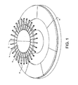
- a support e.g., a table 10, mounted for rotation about an axis 12 by a suitable drive, for example, an electric, hydraulic or pneumatic motor, not shown.
- the table 10 is preferably annular in form and surrounds a mandrel 14 rotatable about axis 12 with table 10.
- Mandrel 14 is also adjustable in elevation relative to table 10.
- the mandrel may be elevated by any suitable, drive, preferably an electric motor.
- the mandrel mounts a plurality of radially outwardly extending fingers 16 which are rotatable with the mandrel 14 and adjustable in height as the mandrel's height is adjusted.
- the tips of the fingers 16 terminate in guides 18 for guiding and locating the punchings about the table in annular arrays thereof as described below.
- each punching has a generally radially extending edge 22, a plurality of full radially extending slots 24 spaced circumferentially one from the other along an inner, circumferentially extending margin and a radially extending half-slot 26 along opposite sides 22 of the punching adjacent the inner margin.
- Each punching may also include an optional dovetail shape 28 at circumferentially spaced locations along the outer margin thereof.
- the radial juncture along the side edges 22 of adjacent punchings 20 of each layer does not underlie the joints between adjacent punchings of adjacent layers.
- the punchings are thus staggered in a circumferential direction relative to one another and the joints of circumferentially adjacent punchings of every fourth layer lie in vertical alignment one with the other.
- each punching forms full slots with the half-slots 26 of the circumferentially adjoining punchings.
- the slots 24 and 26 open radially inwardly for receiving guides 18 as noted below.
- there are fifteen punchings in each annular layer with the side edges 22 of the punchings lying in registration and in a common plane with one another.
- the punchings are stacked one on top of the other in a staggered manner to form a set of a plurality of annular arrays of punchings.
- the sets may be axially spaced from one another on the table by space blocks, not shown, disposed between the sets to form ventilation channels in the finished dynamoelectric machine stator frame.
- the fingers 16 terminate in guides 18.
- Each guide 18 includes a semispherical projection on the top of the associated distal end of the finger 16. The distal end of the finger 16 is received within a slot 24 of a punching 20.
- Multiple sets of punchings are disposed along the table prior to lifting the sets from the table for installation into the dynamoelectric machine frame as described below.
- fifteen punchings form an annular array thereof, the punchings being approximately 0.014 inches thick.
- a vertical height of approximately two inches for each set of punchings is preferred. This requires approximately 140-150 punchings, one over the other, to form a two-inch thick set of punchings in the axial direction.
- any number of punchings of any suitable thickness can be arranged to form a core of any suitable longitudinal length in a dynamoelectric machine (e.g., a motor and/or generator).
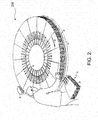
- a station 30 where the punchings 20 are inserted onto table 10 as the table 10 rotates, as indicated by arrow 31, past the inserting station 30.
- an individual locates the punching on top of the table or on top of a previously arranged annular array of punchings. As the individual lays the discrete punchings 20 on the table or on 10 top of a previously placed array, the punchings are disposed so that one or more fingers 16 is received within a full slot 24 or a half-slot 26 of the punching.
- the semi-spherical surfaces 18 assist to guide each punching about the fingers 16 and, hence, align the punching in a selected circumferential and radial position about the table relative to other punchings.
- additional punchings are laid on the table and underlying arrays, with the side edges 22 adjoining one another.
- the individual also staggers the layers of punchings by offsetting the first of an additional 20 layer of punchings relative to the underlying array of punchings so that the joints between the freshly laid punchings do not overlie joints of the underlying punchings.
- the laid punchings may be engaged by a roller system 40 which ensures that the bases of the slots, both full 24 and half-slots 26, are engaged by the guides 18 thereby maintaining an accurate uniform alignment of the slots of the punchings and hence the punchings themselves on the table.
- System 40 maintains rollers against the outer margins of the circumferentially arrayed punchings.
- the mandrel with the attached fingers is also elevated. This is accomplished either continuously or incrementally in response to sensing the height of the uppermost layer of punchings and mechanically raising the mandrel and fingers in response to the sensed signal.
- the completed stack of punchings 20 form a lamination stack 200 that can form the stator core of a dynamoelectric machine (e.g., a motor or a generator).
- FIG. 4 illustrates a top view of a weight distribution plate 400, according to an aspect of the present invention.
- the weight distribution plate 400 may have a generally rectangular shape or be configured to generally conform to a portion of the shape defmed by the lamination stack.
- the weight distribution plate 400 may have one or more hand holds 410 incorporated therein to facilitate manipulation by an operator or technician.
- the weight distribution plate 400 is preferably made of aluminum, aluminum alloy, titanium, titanium alloys, steel, steel alloys or other lightweight material, metal or metal alloy, and have a weight that is comfortably handled by one technician.
- the weight distribution plate 400 could be made of any suitable material, including but not limited to wood, rubber, ceramic or plastic, or combinations thereof.
- FIG. 5 illustrates a top view of a pressing plate 500, according to an aspect of the present invention.
- the pressing plate 500 may have a generally rectangular shape or be configured to generally conform to a portion of the shape defined by the lamination stack.
- the pressing plate 500 may have one or more handles 510 or handholds incorporated therein to facilitate manipulation by an operator or technician.
- the handles 510 could be comprised of brackets mounted to the pressing plate 500, where the brackets also include wire loop type handles.
- the handles 510 could be replaced with hand holds similar to hand holds 410.
- the pressing plate 500 may also include a press contact pad 520, and a press makes contact with this portion of the pressing plate 500.
- the pressing plate 500 is preferably made of aluminum, aluminum alloy, titanium, titanium alloys, steel, steel alloys or other lightweight material, metal or metal alloy, and have a weight that is comfortably handled by one technician.
- the pressing plate 500 could be made of any suitable material, including but not limited to wood, rubber, ceramic or plastic, or combinations thereof.
- the press contact pad 520 could be omitted and a separate set of additional pressing plates could be mounted on top of the pressing plates 500, where the additional pressing plates would facilitate increasing and/or distributing the pressing or compressive force as desired in the specific application.
- the weight distribution plates 400 and/or the pressing plates 500 may be used with air filled bags or containers.
- the air filled bags can be placed between the plates 400, 500 and a force resisting element.
- the air bags can be filled with compressed air to apply a compressive force on the lamination stack 200.
- FIG. 6 illustrates a top plan view of a lamination stack 200 having two weight distribution plates stacked thereon.
- the weight distribution plates 400 are placed on top of the lamination stack 200 and arranged over the entire circumference of the lamination stack 200.
- the lamination stack 200 may be a partially assembled lamination stack or a completed lamination stack. In some applications, it may be desirable to have a "staged" pressing operation where the lamination stack is pressed in stages prior to final completion.
- FIG. 7 illustrates a top plan view of a lamination stack having two weight distribution plates 400 stacked thereon with a pressing plate 500 placed on top of the two weight distribution plates. Only a few plates are shown for clarity, and it is to be understood that both the weight distribution plates 400 and pressing plates 500 would be disposed around the entire circumference of the lamination stack.
- the pressing plates are preferably placed to overlie portions of two weight distribution plates 400.
- the weight distribution plates 400 and pressing plates 500 are set on top of the lamination stack 200. Each plate may cover a span of about 30" to about 36" but plates having any dimension can be used as desired in the specific application.
- the plates 400 and 500 are arranged to cover staggered joints allowing a per square inch (psi) load to be equally spread. After arrangement of the plates 400, 500 a force is put on the pressing plates 500 equaling a pounds per square inch compression generated thru the pressing plate 500 ⁇ weight distribution plate 400 assembly into the core stack lamination assembly 200 of about 40 to 45 psi. However, any suitable pressure can be applied as desired in the specific application.
- the compressive force transferred to the lamination stack 200 compresses the stacked laminations 20 and removes trapped air, waves in the stack and compresses lamination burrs and/or upsets from the punching/laser cutting during the lamination manufacturing process and/or lamination deformities during the stacking process.
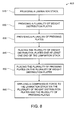
- FIG. 8 is a flow chart of a method 800 for compressing a lamination stack in a dynamoelectric machine.
- the method 800 includes a step 810 of providing a lamination stack, a step 820 of providing a plurality of weight distribution plates, a step 830 of providing a plurality of pressing plates, a step 840 of placing the plurality of weight distribution plates one at least one end of the lamination stack, a step 850 of placing the plurality of pressing plates on the plurality of weight distribution plates, and a step 860 of applying a compressive force to the lamination stack via the plurality of weight distribution plates and the plurality of pressing plates.
- Step 820 can also include providing a plurality of weight distribution plates comprised of aluminum, and/or providing a plurality of handholds in each of the plurality of weight distribution plates.
- Step 830 can also include providing a plurality of pressing plates comprised of aluminum, providing a press contact pad on each of the plurality of pressing plates and/or providing a plurality of handles in each of the plurality of pressing plates.
- Step 840 can also include a step of arranging the plurality of weight distribution plates on the end of the lamination stack so that joints between adjacent punchings are covered by at least one of the plurality of weight distribution plates.
- Step 850 can also include a step of arranging the plurality of pressing plates so that joints between adjacent weight distribution plates are covered by at least one of the plurality of pressing plates.
- the method herein described can be applied to a dynamoelectric machine that is a motor or generator, and a lamination stack used in a stator core.
Landscapes
- Engineering & Computer Science (AREA)
- Manufacturing & Machinery (AREA)
- Power Engineering (AREA)
- Manufacture Of Motors, Generators (AREA)
- Iron Core Of Rotating Electric Machines (AREA)
- Connection Of Motors, Electrical Generators, Mechanical Devices, And The Like (AREA)
Applications Claiming Priority (1)
| Application Number | Priority Date | Filing Date | Title |
|---|---|---|---|
| US12/945,060 US8607697B2 (en) | 2010-11-12 | 2010-11-12 | Method and apparatus for compression of lamination stack for a dynamoelectric machine |
Publications (3)
| Publication Number | Publication Date |
|---|---|
| EP2453561A2 true EP2453561A2 (fr) | 2012-05-16 |
| EP2453561A3 EP2453561A3 (fr) | 2017-12-13 |
| EP2453561B1 EP2453561B1 (fr) | 2020-03-11 |
Family
ID=45062912
Family Applications (1)
| Application Number | Title | Priority Date | Filing Date |
|---|---|---|---|
| EP11188706.3A Active EP2453561B1 (fr) | 2010-11-12 | 2011-11-10 | Procédé et appareil de compression d'un paquet de tôles pour machine dynamo-électrique |
Country Status (4)
| Country | Link |
|---|---|
| US (1) | US8607697B2 (fr) |
| EP (1) | EP2453561B1 (fr) |
| JP (1) | JP5941267B2 (fr) |
| CN (1) | CN102468722B (fr) |
Families Citing this family (1)
| Publication number | Priority date | Publication date | Assignee | Title |
|---|---|---|---|---|
| US11075569B2 (en) * | 2018-12-21 | 2021-07-27 | GM Global Technology Operations LLC | Tooling assembly for engaging wire ends of stator assembly |
Family Cites Families (21)
| Publication number | Priority date | Publication date | Assignee | Title |
|---|---|---|---|---|
| US1025377A (en) * | 1911-07-17 | 1912-05-07 | Craig Engineering Company | Veneer-press. |
| US2492878A (en) * | 1944-11-09 | 1949-12-27 | Miollis Raymond | Method of pressing cheese |
| US2526987A (en) * | 1946-07-08 | 1950-10-24 | Charles S Wilson | Pad press |
| US3652889A (en) * | 1971-01-18 | 1972-03-28 | Gen Electric | Laminated dynamoelectric machine core and method of stacking |
| US3922575A (en) * | 1972-03-30 | 1975-11-25 | Emerson Electric Co | Stator assembly with bore sleeve |
| US4007867A (en) * | 1974-09-05 | 1977-02-15 | General Electric Company | Method of making resiliently compressed laminated core for a dynamoelectric machine |
| US3940648A (en) | 1974-09-05 | 1976-02-24 | General Electric Company | Laminated core and support assembly for a dynamoelectric machine |
| US4479426A (en) | 1982-11-01 | 1984-10-30 | Alfa-Laval Ab | Method of closing, compressing and opening of presses for membrane filters and apparatus for carrying out the method |
| DE3636600A1 (de) | 1986-10-28 | 1988-05-05 | Hoesch Maschinenfabrik Ag | Heizpresse zum verpressen von technischen laminaten |
| US4831301A (en) | 1987-11-04 | 1989-05-16 | General Electric Company | Dynamo-electric machine lamination construction |
| US4810919A (en) * | 1987-11-16 | 1989-03-07 | Westinghouse Electric Corp. | Low-torque nuts for stator core through-bolts |
| US5248911A (en) * | 1992-04-17 | 1993-09-28 | Uppco Inc. | Laminated stator with improved flux pattern |
| JPH08294252A (ja) * | 1995-04-19 | 1996-11-05 | Toyota Motor Corp | モータのステータコア作製用治具 |
| US5875540A (en) * | 1997-01-21 | 1999-03-02 | Siemens Westinghouse Power Corporation | Modular design and manufacture of a stator core |
| US6018207A (en) | 1998-07-10 | 2000-01-25 | General Electric Company | Paired interlocks for flexible indexing of rotated stator cores |
| US6507990B1 (en) * | 2000-03-31 | 2003-01-21 | Schlumberger Technology Corporation | Method of manufacturing a stator |
| US6448686B1 (en) | 2000-12-08 | 2002-09-10 | General Electric Company | Packaged stator core and method forming the same |
| US6865797B2 (en) | 2002-07-16 | 2005-03-15 | General Electric Company | Apparatus for locating and stacking punchings for a generator core |
| US7057324B2 (en) | 2002-12-19 | 2006-06-06 | General Electric Company | Silicon steel punching orientation modifications to lower eddy current losses at the stator core end of dynamoelectric machines |
| US7586067B2 (en) * | 2005-07-01 | 2009-09-08 | Hill Bruce M | Weight-adjustable food press for cooking |
| US8276509B2 (en) | 2010-11-12 | 2012-10-02 | General Electric Company | Method and apparatus for compression of lamination stack for a dynamoelectric machine |
-
2010
- 2010-11-12 US US12/945,060 patent/US8607697B2/en active Active
-
2011
- 2011-11-10 EP EP11188706.3A patent/EP2453561B1/fr active Active
- 2011-11-10 JP JP2011246270A patent/JP5941267B2/ja not_active Expired - Fee Related
- 2011-11-11 CN CN201110370077.4A patent/CN102468722B/zh active Active
Non-Patent Citations (1)
| Title |
|---|
| None |
Also Published As
| Publication number | Publication date |
|---|---|
| JP5941267B2 (ja) | 2016-06-29 |
| EP2453561B1 (fr) | 2020-03-11 |
| CN102468722B (zh) | 2017-03-01 |
| JP2012105534A (ja) | 2012-05-31 |
| CN102468722A (zh) | 2012-05-23 |
| US8607697B2 (en) | 2013-12-17 |
| EP2453561A3 (fr) | 2017-12-13 |
| US20120118177A1 (en) | 2012-05-17 |
Similar Documents
| Publication | Publication Date | Title |
|---|---|---|
| KR102005815B1 (ko) | 마찰판을 제조하기 위한 방법 및 장치 | |
| JP6096460B2 (ja) | コイル製造システム | |
| US9099897B2 (en) | Method for connecting end sections of an annular laminated article and articles made therefrom | |
| KR101861435B1 (ko) | 적층 코어의 자동 분리가 가능한 가열 접착식 회전 적층 코어 제조 장치 | |
| US20170250581A1 (en) | Laminated Core and Method for Producing Same | |
| US8082659B2 (en) | Method of forming a loop winding | |
| KR101861007B1 (ko) | 적층 코어의 자동 분리가 가능한 회전 가열 접착식 회전자 코어 및 고정자 코어 동시 제조 장치 | |
| KR101735246B1 (ko) | 가열 접착식 회전 적층 코어 제조 장치 | |
| JP6771089B2 (ja) | 積層コアの内径加熱が可能な積層コアの製造装置 | |
| US8276509B2 (en) | Method and apparatus for compression of lamination stack for a dynamoelectric machine | |
| KR20180023757A (ko) | 회전자 코어와 고정자 코어의 동시 타발이 가능한 가열 접착식 회전 적층 코어 제조 방법 | |
| EP2453561B1 (fr) | Procédé et appareil de compression d'un paquet de tôles pour machine dynamo-électrique | |
| US20040010906A1 (en) | Apparatus and methods for locating and stacking punchings for a generator stator core | |
| JP2024133989A (ja) | 積層鉄心の製造方法、及び積層鉄心 | |
| JP6834899B2 (ja) | 回転電機コアの製造方法 | |
| JP5735880B2 (ja) | 鉄心製造装置 | |
| JP5606168B2 (ja) | 積層コアの転積方法及び積層コア | |
| JP7292348B2 (ja) | 回転電機の積層鉄心製造方法及び積層鉄心製造装置 | |
| KR101507659B1 (ko) | 고효율 모터용 스파이럴 스테이터 코어의 제조 장치 및 제조 방법 | |
| KR102028214B1 (ko) | 고효율 모터용 스파이럴 스테이터 코어의 가압 장치 및 방법 | |
| KR20180021624A (ko) | 가열 접착식 회전 적층 코어 제조 장치 및 제조 방법 | |
| KR20180021625A (ko) | 적층 코어의 내경 가열이 가능한 적층 코어 제조 장치 및 제조 방법 | |
| JPH0480625B2 (fr) | ||
| KR102028213B1 (ko) | 고효율 모터용 스파이럴 스테이터 코어의 제조 장치 및 제조 방법 | |
| CN105324823B (zh) | 制造线圈装置的方法、端环元件和有端环元件的线圈装置 |
Legal Events
| Date | Code | Title | Description |
|---|---|---|---|
| PUAI | Public reference made under article 153(3) epc to a published international application that has entered the european phase |
Free format text: ORIGINAL CODE: 0009012 |
|
| AK | Designated contracting states |
Kind code of ref document: A2 Designated state(s): AL AT BE BG CH CY CZ DE DK EE ES FI FR GB GR HR HU IE IS IT LI LT LU LV MC MK MT NL NO PL PT RO RS SE SI SK SM TR |
|
| AX | Request for extension of the european patent |
Extension state: BA ME |
|
| PUAL | Search report despatched |
Free format text: ORIGINAL CODE: 0009013 |
|
| AK | Designated contracting states |
Kind code of ref document: A3 Designated state(s): AL AT BE BG CH CY CZ DE DK EE ES FI FR GB GR HR HU IE IS IT LI LT LU LV MC MK MT NL NO PL PT RO RS SE SI SK SM TR |
|
| AX | Request for extension of the european patent |
Extension state: BA ME |
|
| RIC1 | Information provided on ipc code assigned before grant |
Ipc: H02K 15/02 20060101AFI20171109BHEP |
|
| STAA | Information on the status of an ep patent application or granted ep patent |
Free format text: STATUS: REQUEST FOR EXAMINATION WAS MADE |
|
| 17P | Request for examination filed |
Effective date: 20180613 |
|
| RBV | Designated contracting states (corrected) |
Designated state(s): AL AT BE BG CH CY CZ DE DK EE ES FI FR GB GR HR HU IE IS IT LI LT LU LV MC MK MT NL NO PL PT RO RS SE SI SK SM TR |
|
| GRAP | Despatch of communication of intention to grant a patent |
Free format text: ORIGINAL CODE: EPIDOSNIGR1 |
|
| STAA | Information on the status of an ep patent application or granted ep patent |
Free format text: STATUS: GRANT OF PATENT IS INTENDED |
|
| INTG | Intention to grant announced |
Effective date: 20191009 |
|
| GRAS | Grant fee paid |
Free format text: ORIGINAL CODE: EPIDOSNIGR3 |
|
| GRAA | (expected) grant |
Free format text: ORIGINAL CODE: 0009210 |
|
| STAA | Information on the status of an ep patent application or granted ep patent |
Free format text: STATUS: THE PATENT HAS BEEN GRANTED |
|
| AK | Designated contracting states |
Kind code of ref document: B1 Designated state(s): AL AT BE BG CH CY CZ DE DK EE ES FI FR GB GR HR HU IE IS IT LI LT LU LV MC MK MT NL NO PL PT RO RS SE SI SK SM TR |
|
| REG | Reference to a national code |
Ref country code: GB Ref legal event code: FG4D |
|
| REG | Reference to a national code |
Ref country code: CH Ref legal event code: EP |
|
| REG | Reference to a national code |
Ref country code: AT Ref legal event code: REF Ref document number: 1244391 Country of ref document: AT Kind code of ref document: T Effective date: 20200315 |
|
| REG | Reference to a national code |
Ref country code: DE Ref legal event code: R096 Ref document number: 602011065482 Country of ref document: DE |
|
| REG | Reference to a national code |
Ref country code: IE Ref legal event code: FG4D |
|
| PG25 | Lapsed in a contracting state [announced via postgrant information from national office to epo] |
Ref country code: NO Free format text: LAPSE BECAUSE OF FAILURE TO SUBMIT A TRANSLATION OF THE DESCRIPTION OR TO PAY THE FEE WITHIN THE PRESCRIBED TIME-LIMIT Effective date: 20200611 Ref country code: FI Free format text: LAPSE BECAUSE OF FAILURE TO SUBMIT A TRANSLATION OF THE DESCRIPTION OR TO PAY THE FEE WITHIN THE PRESCRIBED TIME-LIMIT Effective date: 20200311 Ref country code: RS Free format text: LAPSE BECAUSE OF FAILURE TO SUBMIT A TRANSLATION OF THE DESCRIPTION OR TO PAY THE FEE WITHIN THE PRESCRIBED TIME-LIMIT Effective date: 20200311 |
|
| REG | Reference to a national code |
Ref country code: NL Ref legal event code: MP Effective date: 20200311 |
|
| PG25 | Lapsed in a contracting state [announced via postgrant information from national office to epo] |
Ref country code: LV Free format text: LAPSE BECAUSE OF FAILURE TO SUBMIT A TRANSLATION OF THE DESCRIPTION OR TO PAY THE FEE WITHIN THE PRESCRIBED TIME-LIMIT Effective date: 20200311 Ref country code: SE Free format text: LAPSE BECAUSE OF FAILURE TO SUBMIT A TRANSLATION OF THE DESCRIPTION OR TO PAY THE FEE WITHIN THE PRESCRIBED TIME-LIMIT Effective date: 20200311 Ref country code: HR Free format text: LAPSE BECAUSE OF FAILURE TO SUBMIT A TRANSLATION OF THE DESCRIPTION OR TO PAY THE FEE WITHIN THE PRESCRIBED TIME-LIMIT Effective date: 20200311 Ref country code: BG Free format text: LAPSE BECAUSE OF FAILURE TO SUBMIT A TRANSLATION OF THE DESCRIPTION OR TO PAY THE FEE WITHIN THE PRESCRIBED TIME-LIMIT Effective date: 20200611 Ref country code: GR Free format text: LAPSE BECAUSE OF FAILURE TO SUBMIT A TRANSLATION OF THE DESCRIPTION OR TO PAY THE FEE WITHIN THE PRESCRIBED TIME-LIMIT Effective date: 20200612 |
|
| REG | Reference to a national code |
Ref country code: LT Ref legal event code: MG4D |
|
| PG25 | Lapsed in a contracting state [announced via postgrant information from national office to epo] |
Ref country code: NL Free format text: LAPSE BECAUSE OF FAILURE TO SUBMIT A TRANSLATION OF THE DESCRIPTION OR TO PAY THE FEE WITHIN THE PRESCRIBED TIME-LIMIT Effective date: 20200311 |
|
| PG25 | Lapsed in a contracting state [announced via postgrant information from national office to epo] |
Ref country code: SM Free format text: LAPSE BECAUSE OF FAILURE TO SUBMIT A TRANSLATION OF THE DESCRIPTION OR TO PAY THE FEE WITHIN THE PRESCRIBED TIME-LIMIT Effective date: 20200311 Ref country code: EE Free format text: LAPSE BECAUSE OF FAILURE TO SUBMIT A TRANSLATION OF THE DESCRIPTION OR TO PAY THE FEE WITHIN THE PRESCRIBED TIME-LIMIT Effective date: 20200311 Ref country code: CZ Free format text: LAPSE BECAUSE OF FAILURE TO SUBMIT A TRANSLATION OF THE DESCRIPTION OR TO PAY THE FEE WITHIN THE PRESCRIBED TIME-LIMIT Effective date: 20200311 Ref country code: LT Free format text: LAPSE BECAUSE OF FAILURE TO SUBMIT A TRANSLATION OF THE DESCRIPTION OR TO PAY THE FEE WITHIN THE PRESCRIBED TIME-LIMIT Effective date: 20200311 Ref country code: RO Free format text: LAPSE BECAUSE OF FAILURE TO SUBMIT A TRANSLATION OF THE DESCRIPTION OR TO PAY THE FEE WITHIN THE PRESCRIBED TIME-LIMIT Effective date: 20200311 Ref country code: PT Free format text: LAPSE BECAUSE OF FAILURE TO SUBMIT A TRANSLATION OF THE DESCRIPTION OR TO PAY THE FEE WITHIN THE PRESCRIBED TIME-LIMIT Effective date: 20200805 Ref country code: SK Free format text: LAPSE BECAUSE OF FAILURE TO SUBMIT A TRANSLATION OF THE DESCRIPTION OR TO PAY THE FEE WITHIN THE PRESCRIBED TIME-LIMIT Effective date: 20200311 Ref country code: IS Free format text: LAPSE BECAUSE OF FAILURE TO SUBMIT A TRANSLATION OF THE DESCRIPTION OR TO PAY THE FEE WITHIN THE PRESCRIBED TIME-LIMIT Effective date: 20200711 |
|
| REG | Reference to a national code |
Ref country code: AT Ref legal event code: MK05 Ref document number: 1244391 Country of ref document: AT Kind code of ref document: T Effective date: 20200311 |
|
| REG | Reference to a national code |
Ref country code: DE Ref legal event code: R097 Ref document number: 602011065482 Country of ref document: DE |
|
| PLBE | No opposition filed within time limit |
Free format text: ORIGINAL CODE: 0009261 |
|
| STAA | Information on the status of an ep patent application or granted ep patent |
Free format text: STATUS: NO OPPOSITION FILED WITHIN TIME LIMIT |
|
| PG25 | Lapsed in a contracting state [announced via postgrant information from national office to epo] |
Ref country code: ES Free format text: LAPSE BECAUSE OF FAILURE TO SUBMIT A TRANSLATION OF THE DESCRIPTION OR TO PAY THE FEE WITHIN THE PRESCRIBED TIME-LIMIT Effective date: 20200311 Ref country code: AT Free format text: LAPSE BECAUSE OF FAILURE TO SUBMIT A TRANSLATION OF THE DESCRIPTION OR TO PAY THE FEE WITHIN THE PRESCRIBED TIME-LIMIT Effective date: 20200311 Ref country code: IT Free format text: LAPSE BECAUSE OF FAILURE TO SUBMIT A TRANSLATION OF THE DESCRIPTION OR TO PAY THE FEE WITHIN THE PRESCRIBED TIME-LIMIT Effective date: 20200311 Ref country code: DK Free format text: LAPSE BECAUSE OF FAILURE TO SUBMIT A TRANSLATION OF THE DESCRIPTION OR TO PAY THE FEE WITHIN THE PRESCRIBED TIME-LIMIT Effective date: 20200311 |
|
| 26N | No opposition filed |
Effective date: 20201214 |
|
| PG25 | Lapsed in a contracting state [announced via postgrant information from national office to epo] |
Ref country code: PL Free format text: LAPSE BECAUSE OF FAILURE TO SUBMIT A TRANSLATION OF THE DESCRIPTION OR TO PAY THE FEE WITHIN THE PRESCRIBED TIME-LIMIT Effective date: 20200311 Ref country code: SI Free format text: LAPSE BECAUSE OF FAILURE TO SUBMIT A TRANSLATION OF THE DESCRIPTION OR TO PAY THE FEE WITHIN THE PRESCRIBED TIME-LIMIT Effective date: 20200311 |
|
| PG25 | Lapsed in a contracting state [announced via postgrant information from national office to epo] |
Ref country code: MC Free format text: LAPSE BECAUSE OF FAILURE TO SUBMIT A TRANSLATION OF THE DESCRIPTION OR TO PAY THE FEE WITHIN THE PRESCRIBED TIME-LIMIT Effective date: 20200311 |
|
| REG | Reference to a national code |
Ref country code: CH Ref legal event code: PL |
|
| PG25 | Lapsed in a contracting state [announced via postgrant information from national office to epo] |
Ref country code: LU Free format text: LAPSE BECAUSE OF NON-PAYMENT OF DUE FEES Effective date: 20201110 |
|
| REG | Reference to a national code |
Ref country code: BE Ref legal event code: MM Effective date: 20201130 |
|
| PG25 | Lapsed in a contracting state [announced via postgrant information from national office to epo] |
Ref country code: CH Free format text: LAPSE BECAUSE OF NON-PAYMENT OF DUE FEES Effective date: 20201130 Ref country code: LI Free format text: LAPSE BECAUSE OF NON-PAYMENT OF DUE FEES Effective date: 20201130 |
|
| PG25 | Lapsed in a contracting state [announced via postgrant information from national office to epo] |
Ref country code: IE Free format text: LAPSE BECAUSE OF NON-PAYMENT OF DUE FEES Effective date: 20201110 |
|
| PG25 | Lapsed in a contracting state [announced via postgrant information from national office to epo] |
Ref country code: TR Free format text: LAPSE BECAUSE OF FAILURE TO SUBMIT A TRANSLATION OF THE DESCRIPTION OR TO PAY THE FEE WITHIN THE PRESCRIBED TIME-LIMIT Effective date: 20200311 Ref country code: MT Free format text: LAPSE BECAUSE OF FAILURE TO SUBMIT A TRANSLATION OF THE DESCRIPTION OR TO PAY THE FEE WITHIN THE PRESCRIBED TIME-LIMIT Effective date: 20200311 Ref country code: CY Free format text: LAPSE BECAUSE OF FAILURE TO SUBMIT A TRANSLATION OF THE DESCRIPTION OR TO PAY THE FEE WITHIN THE PRESCRIBED TIME-LIMIT Effective date: 20200311 |
|
| PG25 | Lapsed in a contracting state [announced via postgrant information from national office to epo] |
Ref country code: MK Free format text: LAPSE BECAUSE OF FAILURE TO SUBMIT A TRANSLATION OF THE DESCRIPTION OR TO PAY THE FEE WITHIN THE PRESCRIBED TIME-LIMIT Effective date: 20200311 Ref country code: AL Free format text: LAPSE BECAUSE OF FAILURE TO SUBMIT A TRANSLATION OF THE DESCRIPTION OR TO PAY THE FEE WITHIN THE PRESCRIBED TIME-LIMIT Effective date: 20200311 |
|
| PG25 | Lapsed in a contracting state [announced via postgrant information from national office to epo] |
Ref country code: BE Free format text: LAPSE BECAUSE OF NON-PAYMENT OF DUE FEES Effective date: 20201130 |
|
| P01 | Opt-out of the competence of the unified patent court (upc) registered |
Effective date: 20230523 |
|
| REG | Reference to a national code |
Ref country code: DE Ref legal event code: R082 Ref document number: 602011065482 Country of ref document: DE Ref country code: DE Ref legal event code: R081 Ref document number: 602011065482 Country of ref document: DE Owner name: GENERAL ELECTRIC TECHNOLOGY GMBH, CH Free format text: FORMER OWNER: GENERAL ELECTRIC COMPANY, SCHENECTADY, NY, US |
|
| REG | Reference to a national code |
Ref country code: GB Ref legal event code: 732E Free format text: REGISTERED BETWEEN 20240222 AND 20240228 |
|
| PGFP | Annual fee paid to national office [announced via postgrant information from national office to epo] |
Ref country code: DE Payment date: 20251022 Year of fee payment: 15 |
|
| PGFP | Annual fee paid to national office [announced via postgrant information from national office to epo] |
Ref country code: GB Payment date: 20251023 Year of fee payment: 15 |
|
| PGFP | Annual fee paid to national office [announced via postgrant information from national office to epo] |
Ref country code: FR Payment date: 20251022 Year of fee payment: 15 |