EP2454433B1 - Türanordnung mit zwei scharnieren mit selbsteinzug - Google Patents
Türanordnung mit zwei scharnieren mit selbsteinzug Download PDFInfo
- Publication number
- EP2454433B1 EP2454433B1 EP10747793.7A EP10747793A EP2454433B1 EP 2454433 B1 EP2454433 B1 EP 2454433B1 EP 10747793 A EP10747793 A EP 10747793A EP 2454433 B1 EP2454433 B1 EP 2454433B1
- Authority
- EP
- European Patent Office
- Prior art keywords
- hinge
- sleeve
- door assembly
- central shaft
- base position
- Prior art date
- Legal status (The legal status is an assumption and is not a legal conclusion. Google has not performed a legal analysis and makes no representation as to the accuracy of the status listed.)
- Not-in-force
Links
- 238000006073 displacement reaction Methods 0.000 claims description 32
- 230000006835 compression Effects 0.000 description 2
- 238000007906 compression Methods 0.000 description 2
- 230000002093 peripheral effect Effects 0.000 description 2
- 230000002040 relaxant effect Effects 0.000 description 2
- 241000251468 Actinopterygii Species 0.000 description 1
- 240000001439 Opuntia Species 0.000 description 1
- 235000004727 Opuntia ficus indica Nutrition 0.000 description 1
- 238000005452 bending Methods 0.000 description 1
- 230000001419 dependent effect Effects 0.000 description 1
- 230000005484 gravity Effects 0.000 description 1
- 238000003780 insertion Methods 0.000 description 1
- 230000037431 insertion Effects 0.000 description 1
- 239000002184 metal Substances 0.000 description 1
- 230000000979 retarding effect Effects 0.000 description 1
Images


Classifications
-
- E—FIXED CONSTRUCTIONS
- E05—LOCKS; KEYS; WINDOW OR DOOR FITTINGS; SAFES
- E05F—DEVICES FOR MOVING WINGS INTO OPEN OR CLOSED POSITION; CHECKS FOR WINGS; WING FITTINGS NOT OTHERWISE PROVIDED FOR, CONCERNED WITH THE FUNCTIONING OF THE WING
- E05F1/00—Closers or openers for wings, not otherwise provided for in this subclass
- E05F1/08—Closers or openers for wings, not otherwise provided for in this subclass spring-actuated, e.g. for horizontally sliding wings
- E05F1/10—Closers or openers for wings, not otherwise provided for in this subclass spring-actuated, e.g. for horizontally sliding wings for swinging wings, e.g. counterbalance
- E05F1/12—Mechanisms in the shape of hinges or pivots, operated by springs
- E05F1/1207—Mechanisms in the shape of hinges or pivots, operated by springs with a coil spring parallel with the pivot axis
- E05F1/1215—Mechanisms in the shape of hinges or pivots, operated by springs with a coil spring parallel with the pivot axis with a canted-coil torsion spring
-
- E—FIXED CONSTRUCTIONS
- E05—LOCKS; KEYS; WINDOW OR DOOR FITTINGS; SAFES
- E05D—HINGES OR SUSPENSION DEVICES FOR DOORS, WINDOWS OR WINGS
- E05D3/00—Hinges with pins
- E05D3/02—Hinges with pins with one pin
- E05D2003/025—Hinges with pins with one pin having three knuckles
-
- E—FIXED CONSTRUCTIONS
- E05—LOCKS; KEYS; WINDOW OR DOOR FITTINGS; SAFES
- E05Y—INDEXING SCHEME ASSOCIATED WITH SUBCLASSES E05D AND E05F, RELATING TO CONSTRUCTION ELEMENTS, ELECTRIC CONTROL, POWER SUPPLY, POWER SIGNAL OR TRANSMISSION, USER INTERFACES, MOUNTING OR COUPLING, DETAILS, ACCESSORIES, AUXILIARY OPERATIONS NOT OTHERWISE PROVIDED FOR, APPLICATION THEREOF
- E05Y2201/00—Constructional elements; Accessories therefor
- E05Y2201/40—Motors; Magnets; Springs; Weights; Accessories therefor
- E05Y2201/404—Function thereof
- E05Y2201/41—Function thereof for closing
- E05Y2201/412—Function thereof for closing for the final closing movement
-
- E—FIXED CONSTRUCTIONS
- E05—LOCKS; KEYS; WINDOW OR DOOR FITTINGS; SAFES
- E05Y—INDEXING SCHEME ASSOCIATED WITH SUBCLASSES E05D AND E05F, RELATING TO CONSTRUCTION ELEMENTS, ELECTRIC CONTROL, POWER SUPPLY, POWER SIGNAL OR TRANSMISSION, USER INTERFACES, MOUNTING OR COUPLING, DETAILS, ACCESSORIES, AUXILIARY OPERATIONS NOT OTHERWISE PROVIDED FOR, APPLICATION THEREOF
- E05Y2201/00—Constructional elements; Accessories therefor
- E05Y2201/40—Motors; Magnets; Springs; Weights; Accessories therefor
- E05Y2201/404—Function thereof
- E05Y2201/422—Function thereof for opening
- E05Y2201/424—Function thereof for opening for the final opening movement
-
- E—FIXED CONSTRUCTIONS
- E05—LOCKS; KEYS; WINDOW OR DOOR FITTINGS; SAFES
- E05Y—INDEXING SCHEME ASSOCIATED WITH SUBCLASSES E05D AND E05F, RELATING TO CONSTRUCTION ELEMENTS, ELECTRIC CONTROL, POWER SUPPLY, POWER SIGNAL OR TRANSMISSION, USER INTERFACES, MOUNTING OR COUPLING, DETAILS, ACCESSORIES, AUXILIARY OPERATIONS NOT OTHERWISE PROVIDED FOR, APPLICATION THEREOF
- E05Y2800/00—Details, accessories and auxiliary operations not otherwise provided for
- E05Y2800/15—Applicability
- E05Y2800/17—Universally applicable
-
- E—FIXED CONSTRUCTIONS
- E05—LOCKS; KEYS; WINDOW OR DOOR FITTINGS; SAFES
- E05Y—INDEXING SCHEME ASSOCIATED WITH SUBCLASSES E05D AND E05F, RELATING TO CONSTRUCTION ELEMENTS, ELECTRIC CONTROL, POWER SUPPLY, POWER SIGNAL OR TRANSMISSION, USER INTERFACES, MOUNTING OR COUPLING, DETAILS, ACCESSORIES, AUXILIARY OPERATIONS NOT OTHERWISE PROVIDED FOR, APPLICATION THEREOF
- E05Y2800/00—Details, accessories and auxiliary operations not otherwise provided for
- E05Y2800/20—Combinations of elements
- E05Y2800/21—Combinations of elements of identical elements, e.g. of identical compression springs
Definitions
- the invention relates to a door assembly with a frame and with a door leaf, wherein the frame and the door leaf are connected by at least two hinges, wherein a hinge two relatively pivotable between a basic position and an end position leg and at least one opposite to the starting from the basic position Has pivoting direction acting spring element.
- a spring hinge is known, which is pulled from each angular position in a closed position.
- the Zuziehmoment is reinforced in an adjacent to the closed end angular range by parallel connection of a second spring.
- From the EP 1 900 896 A2 is a self-closing door known.
- the door is raised during the pivoting movement against gravity and under load of a compression spring along a backdrop.
- the closing is supported by the relaxing compression spring.
- the present invention is based on the problem to develop a door assembly with at least two hinges with self-closing, wherein the self-closing of the door assembly is limited in both end positions each on a partial pivot angle.
- a leg carries a central shaft and the other leg coaxial with the central shaft outer sleeve. Between the central shaft and the outer sleeve, an intermediate sleeve is arranged.
- the hinge comprises at least one displacement body, which is mounted in the basic position of the hinge in an opening of the intermediate sleeve and either in a recess of the central shaft or in a receptacle of the outer sleeve, wherein at least in the basic position, the recess and the receptacle are not arranged radially to each other.
- the spring element is arranged between the intermediate sleeve and the outer body or central shaft which does not bear the displacer body in the basic position.
- the pivot angle range adjacent to the basic position is limited by the pivot angle in which the recess and the receptacle are arranged radially relative to one another.
- the displaced in the pivoting direction in this pivoting angle of the recess in the receptacle or from the receptacle into the recess displacement body locks the spring element.
- One hinge has an open basic position and another hinge has a closed basic position. Between the pivoting angle ranges, in each of which a hinge is pulled into its normal position, a freewheeling angle range is arranged.
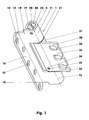
- FIG. 1 shows a hinge (1), eg a cylinder belt (1).
- a hinge (1) eg a cylinder belt (1).
- Such fittings are used on windows or doors, the pivot angle of a closed position in an open position, for example, up to 180 degrees.
- the cylinder bands (1) can be designed for the right or left stop of a window or a door.
- the door may be a building or room or vehicle door. Also, the use in the door of a stationary or built in a vehicle home appliance, such as a refrigerator of a motor home, conceivable.
- the Anschraubband shown (1) has two relative to each other about a pivot axis (5) pivotable leg (10, 30). It connects e.g. a frame or a frame with a door leaf.
- the first, for example, fixed leg (10) is e.g. fastened by means of fastening screws to the frame.
- the second leg (30) is then struck on the door leaf.
- the hinge (1) can also be fastened with the first leg (10) on the door leaf and with the second leg (30) on the frame. It can also be designed as a drill tape, fish tape, pot band, etc.
- the fixed leg in the exemplary embodiment (10) consists of a metal sheet. This forms two aligned and largely cylindrical sleeve sections (11, 12) which are connected by means of an L-shaped bent web (13).
- the imaginary bending line (14) is parallel to the pivot axis (5) of the hinge (1).
- the fastening tab (16) Adjacent thereto, the fastening tab (16), for example, five countersunk recesses (17) for Recording example of mounting screws has. At its two ends of the fastening tabs (16) eg notches (18).
- the Indian FIG. 1 pivotable legs (30) comprises in the illustration of FIG. 1 a largely cylindrical sleeve portion (31) and a fastening tab (32).
- the latter has, for example, three notches (33) for receiving eg fastening screws.
- a breakthrough (34) sits a retaining bolt (24) having a second hinge pin (70), see. FIG. 2 , wearing.
- the pivotable leg (30) is mounted by means of sliding sleeves (21, 22) in the fixed leg (10).
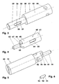
- the FIG. 2 shows an exploded view of the hinge (1).
- the first hinge pin (50) comprises a central shaft (51).
- the central shaft (51) is as an item in the FIG. 3 shown. This is a cylindrical shaft with two diameter ranges (52, 53).
- the larger diameter region (52) has, for example, two radial bores (54) offset by a quarter circle from each other. In the assembled state, one of these bores (54) receives the retaining bolt (23).
- the offset area (53) has, for example, a total of three recesses (55), of which in the figure the Figures 2 and 3 only one longitudinal groove (55) is shown.
- the two other longitudinal grooves are arranged, for example, on the same imaginary cylinder as the first longitudinal groove (55). In the direction of the pivot axis (5) the grooves are offset from each other so that the cylinder sections comprising the longitudinal grooves do not overlap.
- the single longitudinal groove (55) for example, has the shape of a keyway. It has in cross-section a flat groove bottom (56) and at right angles to the groove bottom (56) arranged groove flanks (57).
- the cross section of the groove (55) may also be circular segment-shaped.
- the individual longitudinal grooves can have different lengths.
- the intermediate sleeve (60) On the central shaft (51) sits an intermediate sleeve (60). In the assembled state, the intermediate sleeve (60) engages around the peripheral surface (59) of the central shaft (51). In the FIG. 4 the intermediate sleeve (60) is shown as a single part.
- the intermediate sleeve (60) comprises a sleeve-like portion (61), a guide pin (62) and a stop (63).
- the sleeve-like portion (61), for example, has a constant wall thickness.
- the outer diameter of the sleeve-like portion (61) is smaller than the diameter of the larger diameter portion (53) of the central shaft (51).
- the sleeve wall (64) has, for example, three radially oriented apertures (65) whose arrangement and size correspond to the arrangement and size of the longitudinal grooves (55) of the central shaft (51).
- the guide pin (62) is for example a cylindrical pin whose diameter is about 40% of the outer diameter of the intermediate sleeve (60).
- the block-shaped stop (63) has, for example, a stop surface (67).
- the pivot axis (5) is parallel, for example to the plane of this stop surface (67). It can also be in this plane.
- the second hinge pin (70) comprises in the exemplary embodiment an outer sleeve (71) and an extension part (72).
- the inner diameter of the cylinder jacket-shaped outer sleeve (71) is for example larger than the outer diameter of the intermediate sleeve (60).
- the outer diameter of the outer sleeve (71) is smaller than the inner diameter of the sleeve portion (31) of the movable leg (30).
- the sleeve wall (73) has a constant cross-section. It has four each through a quarter circle offset through holes (74) and three receptacles (75), of which in the illustration of FIG. 2 only one receptacle (75) is shown.
- the receptacles (75) are formed in the embodiment as elongated holes (75). But they can also be formed as depressions of the inner wall (76) of the outer sleeve (71).
- the location and size of the receptacles (75) corresponds to the position and size of the openings (65) of the intermediate sleeve (60).
- the extension part (72) consists in the embodiment of a cylindrical portion (77), a remote for this, also cylindrical portion (78), a guide pin (79) and a stop (81).
- the extension part is shown as a single part.
- the cylindrical portion (77) has an end-side adjustment slot (83).
- the stepped cylindrical portion (78) has two, for example, by a quarter circle staggered through holes (82).
- the stop (81) and the guide pin (79) are constructed as the stop (63) and the guide pin (62) of the intermediate sleeve (60).
- the in the FIG. 5 visible abutment surface (86) of the stop (81) has in the illustration of FIG. 2 downward.
- the hinge (1) comprises, for example, three displacement bodies (90) and a spring element (100).
- the displacement body (90) are in the embodiment cylinder (91, 92), whose end faces (93) are formed as tips, see. FIG. 6 ,
- the displacement body (90) may also be disc or ball-shaped.
- the in the FIG. 2 shown displacement body (90) have different lengths.
- the long cylindrical body (91) is slightly shorter than the long hole (65). Its diameter is smaller than the width of this slot (65).
- the two shorter bodies (92) are shorter than those in the Figures 2 and 4 concealed, shorter slots (65).
- the spring element (100) is in the exemplary embodiment, a coil spring (101) in the design of a torsion spring.
- the torsion spring (101) has straight ends (102), for example.
- the intermediate sleeve (60) When mounting the hinge (1), for example, first the intermediate sleeve (60) is fitted onto the central shaft (51). Here, the intermediate sleeve (60) is rotated so that the slots (65) over the longitudinal grooves (55) are. Next, the displacers (90) are then inserted into the elongated holes (65). After insertion, the displacement body (90) is flush with the lateral surface (68) of the intermediate sleeve (60) or immerse in the sleeve wall (64). The outer sleeve (71) is placed on the intermediate sleeve (60) so that the receptacles (75) are not aligned with the oblong holes (65).
- the thus prepared unit can be inserted into the two mutually aligned, with the interposition of the sliding sleeves (21, 22) arranged legs (10, 30).
- the first retaining pin (23) through the openings (19) and the through holes (54) are mounted.
- the spring (100) and the extension part (72) used.
- the second retaining bolt (24) is mounted through the apertures (34) and through-holes (74) and (82).
- the central shaft (51), the intermediate sleeve (60) and the outer sleeve (71) are coaxial with each other and coaxial with the pivot axis (5).
- a screwdriver can be used, which engages in the adjustment slot (83).
- the thus prepared hinge is e.g. mounted on a frame and on a door leaf.
- the second hinge pin (70) is pivotable about the pivot axis (5) relative to the first hinge pin (50).
- the pivot angle of the hinge (1) from the basic position (6) to the end position in the exemplary embodiment is 110 degrees. It can also be 130 degrees.
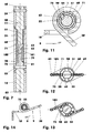
- FIG. 7 shows a longitudinal section of the hinge (1).
- FIG. 8 is a cross section of this hinge (1) shown.
- the sectional plane of this illustration for example, intersects the long cylindrical body (91).
- the door leaf is closed, for example.
- This closed pivot position of the hinge (1) is referred to below as the basic position (6).
- the movable leg (30) pivots with the outer sleeve (71) and the extension part (72) in the illustration of FIGS. 8 and 9 in the pivoting direction (8) counterclockwise.
- the outer sleeve (71) rotates about the pivot axis (5) relative to the fixed central shaft (51), the intermediate sleeve (60) and the displacement bodies (90).
- the stops (63, 81) abut with the abutment surfaces (67, 86) against the ends (102) of the spring (100).
- the spring element (100) is twisted and thereby tightened.
- the displacers (90) maintain their position relative to the fixed leg (10). The holding forces are distributed in the embodiment over all three displacement body (90).
- pivot angle in which the receptacles (75) of the outer sleeve (71) radially outside the slots (65) and the longitudinal grooves (55). This, in the FIG. 9 shown pivot angle is for example 45 degrees.
- the displacement bodies (90) Upon further pivoting in the pivoting direction (8), the displacement bodies (90) are displaced radially outwards in the direction of the receptacles (75) of the outer sleeve (71) by means of the off-center acting force of the central shaft (51).
- FIG. 11 In this illustration, the displacement bodies (90) are already displaced radially outward from the groove base (56) in the direction of the outer sleeve (71).
- the displacement bodies (90) project over the sleeve wall (64) both in the direction of the outer sleeve (71) and also in the direction of the longitudinal groove (55).
- the displacement body (90) Upon further rotation of the movable leg (30) in the pivoting direction (8), the displacement body (90) are further displaced into the receptacle (75) of the outer sleeve (71). After displacement, the displacement body (90) in the slots (65) and in the receptacles (75). They prevent further rotation of the intermediate sleeve (60) relative to the outer sleeve (71). Since the outer sleeve (71) and the intermediate sleeve (60) no longer rotate relative to each other during further pivoting in the pivoting direction (8), the spring element (100) is not stretched further. The spring element (100) now remains in the cocked position.
- the movable leg (30) Upon further pivoting of the door leaf, the movable leg (30) continues to rotate with the outer sleeve (71) and the intermediate sleeve (60).
- the spring element (100) remains taut so that the door leaf can be opened further in the freewheel. It can now be stopped in any position and will then stay in that position.
- Such a hinge position is in the FIG. 10 shown.
- the hinge (1) is pivoted in this illustration by an angle of 90 degrees.
- the door hinge (1) When closing the door leaf, the door hinge (1), for example, from in the FIG. 10 shown position clockwise, ie opposite to the pivoting direction (8) in the in the FIG. 8 pivoted position shown.
- the spring element (100) is initially stretched.
- the outer sleeve (71), the intermediate sleeve (60) and the displacement body (90) are pivoted.
- the door leaf can be up in the FIG. 9 Position is reached, stopped at any time.
- the relaxing spring (100) causes a relative movement of the intermediate sleeve (60) to the outer sleeve (71).
- the displacement body (90) are taken and displaced radially inward from the edge (84) of the receptacles (75).
- the displacement body (90) are received by the longitudinal grooves (55).
- the spring (100) continues to relax. It pushes the stop surfaces (67, 86) of the intermediate sleeve (60) and the extension part (72) apart and pulls the door leaf in its closed basic position (6).
- FIGS. 12 and 13 show a simplified example of a hinge (1) with freewheel and self-closing.
- the device comprises two displacement bodies (90) and two spring elements (100).
- the latter are tension springs (103) which are each arranged between two spring pins (69, 85) of the intermediate sleeve (60) and the outer sleeve (71).
- the displacement body (90) are displaced to the outside during further rotation of the central shaft (51). They are pushed out of the longitudinal grooves (55) of the central shaft (51) and pushed into the receptacles (75) of the outer sleeve (71). Upon further rotation of the central shaft (51) only this turns on alone.
- the intermediate sleeve (60) with the displacement bodies (90) stops.
- the spring tension is not changed during further rotation of the central shaft (51).
- the spring (100) is locked by means of the displacement body (90).
- the intermediate sleeve (60) may be segmented, e.g. in two bowls. In the assembled state, the displacement body (90) then lie between the shells.
- the central shaft (51) can be integrated in one of the hinge wings (10, 30). It is also conceivable that the outer sleeve (71) in the other leg (30, 10) is integrated. For example, then the recesses (75) are introduced into the movable leg (30).
- the hinge (1) can also be constructed so that it is open in its basic position (9), cf. FIG. 14 ,
- the pivot angle of the basic position (9) to the closed end position is 110 degrees.
- the spring element (100) is tensioned and locked in a predetermined swivel angle position when closing in a swivel angle region adjoining the basic position (9). The further closing of the hinge (1) then takes place without further tensioning of the spring element (100).
- opening the hinge (1) is pulled from the predetermined pivoting angle position with relaxation of the spring element (100) in the open basic position (9).
- a freewheeling angle range is used in a plurality of hinges (1) on a door of the hinges with a collection device in the closed position and one of the hinges with a collection device in the open position.
- the self-closing hinge (1) may be combined with a cushioning and / or a retarding device.
Landscapes
- Closing And Opening Devices For Wings, And Checks For Wings (AREA)
- Hinges (AREA)
Description
- Die Erfindung betrifft eine Türanordnung mit einer Zarge und mit einem Türblatt, wobei die Zarge und das Türblatt mittels mindestens zwei Scharnieren verbunden sind, wobei ein Scharnier zwei relativ zueinander zwischen einer Grundstellung und einer Endstellung schwenkbare Schenkel und mit mindestens ein entgegen der von der Grundstellung ausgehenden Schwenkrichtung wirkendes Federelement aufweist.
- Aus der
DE 1 947 513 ist ein Federscharnier bekannt, das aus jeder Winkellage in eine geschlossene Stellung zugezogen wird. Das Zuziehmoment ist in einem an die geschlossene Endlage angrenzenden Winkelbereich durch Parallelschaltung einer zweiten Feder verstärkt. - Aus der
EP 1 900 896 A2 ist eine selbstschließende Tür bekannt. Die Tür wird bei der Aufschwenkbewegung entgegen der Schwerkraft und unter Belastung einer Druckfeder entlang einer Kulisse angehoben. Das Schließen wird durch die sich entspannende Druckfeder unterstützt. - Der vorliegenden Erfindung liegt die Problemstellung zugrunde, eine Türanordnung mit mindestens zwei Scharnieren mit Selbsteinzug zu entwickeln, wobei der Selbsteinzug der Türanordnung in beide Endlagen jeweils auf einen Teilschwenkwinkel begrenzt ist.
- Diese Problemstellung wird mit den Merkmalen des Hauptanspruches gelöst. Dazu trägt ein Schenkel eine Zentralwelle und der andere Schenkel eine zur Zentralwelle koaxiale Außenhülse. Zwischen der Zentralwelle und der Außenhülse ist eine Zwischenhülse angeordnet. Das Scharnier umfasst mindestens einen Verdrängungskörper, der in der Grundstellung des Scharniers in einem Durchbruch der Zwischenhülse und entweder in einer Ausnehmung der Zentralwelle oder in einer Aufnahme der Außenhülse gelagert ist, wobei zumindest in der Grundstellung die Ausnehmung und die Aufnahme nicht radial zueinander angeordnet sind. Das Federelement ist zwischen der Zwischenhülse und der in der Grundstellung den Verdrängungskörper nicht lagernden Außenhülse oder Zentralwelle angeordnet. Der an die Grundstellung angrenzende Schwenkwinkelbereich ist durch den Schwenkwinkel begrenzt, in dem die Ausnehmung und die Aufnahme radial zueinander angeordnet sind. Der beim Schwenken in die Schwenkrichtung in diesem Schwenkwinkel von der Ausnehmung in die Aufnahme oder von der Aufnahme in die Ausnehmung verdrängte Verdrängungskörper arretiert das Federelement. Ein Scharnier hat eine geöffnete Grundstellung und ein anderes Scharnier hat eine geschlossene Grundstellung. Zwischen den Schwenkwinkelbereichen, in denen jeweils ein Scharnier in seine Grundstellung gezogen wird, ist ein Freilaufwinkelbereich angeordnet.
- Weitere Einzelheiten der Erfindung ergeben sich aus den Unteransprüchen und der nachfolgenden Beschreibung schematisch dargestellter Ausführungsformen.
- Figur 1:
- Scharnier;
- Figur 2:
- Explosionszeichnung von
Figur 1 ; - Figur 3:
- Zentralwelle;
- Figur 4:
- Zwischenhülse;
- Figur 5:
- Verlängerungsteil;
- Figur 6:
- Verdrängungskörper;
- Figur 7:
- Längsschnitt von
Figur 1 ; - Figur 8:
- Querschnitt von
Figur 1 ; - Figur 9:
- Querschnitt des Scharniers am Ende des Schwenkwinkelbereichs;
- Figur 10:
- Querschnitt des aufgeschwenkten Scharniers;
- Figur 11:
- Verschieben des Verdrängungskörpers;
- Figur 12:
- Modell des Scharniers;
- Figur 13:
-
Figur 12 bei geschwenktem Schenkel; - Figur 14:
- Scharnier mit geöffneter Grundstellung.
- Die
Figur 1 zeigt ein Scharnier (1), z.B. ein Zylinderband (1). Derartige Beschläge werden an Fenstern oder Türen eingesetzt, deren Schwenkwinkel von einer geschlossenen Lage in eine offene Lage z.B. bis zu 180 Grad beträgt. Die Zylinderbänder (1) können für den Rechts- oder Linksanschlag eines Fensters oder einer Tür ausgeführt sein. Die Tür kann eine Gebäude- oder Raum- oder Fahrzeugtür sein. Auch ist der Einsatz in der Tür eines stationären oder in einem Fahrzeug eingebauten Haushaltsgeräts, z.B. eines Kühlschranks eines Wohnmobils, denkbar. - Das dargestellte Anschraubband (1) hat zwei relativ zueinander um eine Schwenkachse (5) schwenkbare Schenkel (10, 30). Es verbindet z.B. eine Zarge oder einen Blendrahmen mit einem Türblatt. Der erste, beispielsweise feststehende Schenkel (10) ist z.B. mittels Befestigungsschrauben an der Zarge befestigbar. Der zweite Schenkel (30) ist dann am Türblatt angeschlagen.
- Das Scharnier (1) kann auch mit dem ersten Schenkel (10) am Türblatt und mit dem zweiten Schenkel (30) an der Zarge befestigbar sein. Auch kann es als Einbohrband, Fischband, Topfband, etc. ausgebildet sein.
- Der im Ausführungsbeispiel feststehende Schenkel (10) besteht aus einem Blech. Dieses bildet zwei miteinander fluchtende und weitgehend zylindrische Hülsenabschnitte (11, 12), die mittels eines L-förmig gebogenen Steges (13) verbunden sind. Die gedachte Biegelinie (14) ist parallel zur Schwenkachse (5) des Scharniers (1). An diese grenzt der Befestigungslappen (16) an, der beispielsweise fünf angesenkte Ausnehmungen (17) zur Aufnahme z.B. von Befestigungsschrauben aufweist. An seinen beiden Enden hat der Befestigungslappen (16) z.B. Ausklinkungen (18).
- In einem im Hülsenabschnitt (11) angeordneten Durchbruch (19) sitzt ein Haltebolzen (23), der einen ersten Scharnierzapfen (50) als Teil des Scharnierdorns trägt.
- Der in der
Figur 1 schwenkbare Schenkel (30) umfasst in der Darstellung derFigur 1 einen weitgehend zylindrischen Hülsenabschnitt (31) und einen Befestigungslappen (32). Letzterer weist z.B. drei Ausklinkungen (33) zur Aufnahme z.B. von Befestigungsschrauben auf. In einem Durchbruch (34) sitzt ein Haltebolzen (24), der einen zweiten Scharnierzapfen (70), vgl.Figur 2 , trägt. - Der schwenkbare Schenkel (30) ist mittels Gleithülsen (21, 22) im feststehenden Schenkel (10) gelagert.
- Die
Figur 2 zeigt eine Explosionszeichnung des Scharniers (1). Der erste Scharnierzapfen (50) umfasst eine Zentralwelle (51). Die Zentralwelle (51) ist als Einzelteil in derFigur 3 dargestellt. Dies ist eine zylindrische Welle mit zwei Durchmesserbereichen (52, 53). Der größere Durchmesserbereich (52) hat beispielsweise zwei um einen Viertelkreis zueinander versetzte, radial orientierte Durchgangsbohrungen (54). Im montierten Zustand nimmt eine dieser Bohrungen (54) den Haltebolzen (23) auf. - Der abgesetzte Bereich (53) hat z.B. insgesamt drei Ausnehmungen (55), von denen in der Abbildung der
Figuren 2 und3 nur eine Längsnut (55) dargestellt ist. Die beiden anderen Längsnuten sind beispielsweise auf demselben gedachten Zylinder wie die erste Längsnut (55) angeordnet. In Richtung der Schwenkachse (5) sind die Nuten zueinander versetzt, so dass sich die die Längsnuten umfassenden Zylinderabschnitte nicht überdecken. - Die einzelne Längsnut (55) hat beispielsweise die Gestalt einer Paßfedernut. Sie hat im Querschnitt einen ebenen Nutgrund (56) und rechtwinklig zum Nutgrund (56) angeordnete Nutflanken (57). Der Querschnitt der Nut (55) kann auch kreissegmentförmig sein. Die einzelnen Längsnuten können unterschiedliche Längen aufweisen.
- Auf der Zentralwelle (51) sitzt eine Zwischenhülse (60). Im montierten Zustand umgreift die Zwischenhülse (60) die Umfangsfläche (59) der Zentralwelle (51). In der
Figur 4 ist die Zwischenhülse (60) als Einzelteil dargestellt. Die Zwischenhülse (60) umfasst einen hülsenartigen Abschnitt (61), einen Führungszapfen (62) und einen Anschlag (63). - Der hülsenartige Abschnitt (61) hat beispielsweise eine konstante Wandstärke. Der Außendurchmesser des hülsenartigen Abschnitts (61) ist kleiner als der Durchmesser des größeren Durchmesserbereichs (53) der Zentralwelle (51). Die Hülsenwandung (64) hat beispielsweise drei radial orientierte Durchbrüche (65), deren Anordnung und Größe der Anordnung und Größe der Längsnuten (55) der Zentralwelle (51) entspricht.
- Der Führungszapfen (62) ist beispielsweise ein zylindrischer Zapfen, dessen Durchmesser etwa 40 % des Außendurchmessers der Zwischenhülse (60) beträgt.
- An den Führungszapfen (62) und an die Stirnseite (66) des hülsenartigen Abschnitts (61) ist der Anschlag (63) z.B. angeformt. Der quaderförmige Anschlag (63) hat z.B. eine Anschlagfläche (67). Die Schwenkachse (5) liegt beispielsweise parallel zur Ebene dieser Anschlagfläche (67). Sie kann auch in dieser Ebene liegen.
- Der zweite Scharnierzapfen (70) umfasst im Ausführungsbeispiel eine Außenhülse (71) und ein Verlängerungsteil (72).
- Der Innendurchmesser der zylindermantelförmigen Außenhülse (71) ist beispielsweise größer als der Außendurchmesser der Zwischenhülse (60). Der Außendurchmesser der Außenhülse (71) ist kleiner als der Innendurchmesser des Hülsenabschnitts (31) des beweglichen Schenkels (30). Die Hülsenwandung (73) hat einen konstanten Querschnitt. Sie weist vier jeweils um einen Viertelkreis zueinander versetzte Durchgangsbohrungen (74) sowie drei Aufnahmen (75) auf, von denen in der Darstellung der
Figur 2 nur eine Aufnahme (75) dargestellt ist. Die Aufnahmen (75) sind im Ausführungsbeispiel als Langlöcher (75) ausgebildet. Sie können aber auch als Einsenkungen der Innenwandung (76) der Außenhülse (71) ausgebildet sein. Die Lage und Größe der Aufnahmen (75) korrespondiert mit der Lage und Größe der Durchbrüche (65) der Zwischenhülse (60). - Das Verlängerungsteil (72) besteht im Ausführungsbeispiel aus einem zylindrischen Abschnitt (77), einem hierzu abgesetzten, ebenfalls zylindrischen Abschnitt (78), einem Führungszapfen (79) und einem Anschlag (81). In der
Figur 5 ist das Verlängerungsteil als Einzelteil dargestellt. Der zylindrische Abschnitt (77) hat einen stirnseitigen Einstellschlitz (83). Der abgesetzte zylindrische Abschnitt (78) hat zwei z.B. um einen Viertelkreis zueinander versetzte Durchgangsbohrungen (82). Der Anschlag (81) und der Führungszapfen (79) sind so aufgebaut wie der Anschlag (63) und der Führungszapfen (62) der Zwischenhülse (60). Die in derFigur 5 sichtbare Anschlagfläche (86) des Anschlags (81) weist in der Darstellung derFigur 2 nach unten. - Weiterhin umfasst das Scharnier (1) z.B. drei Verdrängungskörper (90) und ein Federelement (100). Die Verdrängungskörper (90) sind im Ausführungsbeispiel Zylinder (91, 92), deren Stirnseiten (93) als Spitzen ausgebildet sind, vgl.
Figur 6 . Die Verdrängungskörper (90) können aber auch scheiben- oder kugelartig ausgebildet sein. Die in derFigur 2 dargestellten Verdrängungskörper (90) haben unterschiedliche Längen. Der lange zylindrische Körper (91) ist geringfügig kürzer als das Langloch (65). Sein Durchmesser ist kleiner als die Breite dieses Langlochs (65). Die beiden kürzeren Körper (92) sind kürzer als die in denFiguren 2 und4 verdeckten, kürzeren Langlöcher (65). - Das Federelement (100) ist im Ausführungsbeispiel eine Spiralfeder (101) in der Bauform einer Torsionsfeder. Die Torsionsfeder (101) hat beispielsweise gerade Enden (102).
- Bei der Montage des Scharniers (1) wird beispielsweise zunächst die Zwischenhülse (60) auf die Zentralwelle (51) aufgesteckt. Hierbei wird die Zwischenhülse (60) so gedreht, dass die Langlöcher (65) über den Längsnuten (55) stehen. Als nächstes werden dann die Verdrängungskörper (90) in die Langlöcher (65) eingesetzt. Nach dem Einsetzen sind die Verdrängungskörper (90) bündig mit der Mantelfläche (68) der Zwischenhülse (60) oder tauchen in die Hülsenwandung (64) ein. Die Außenhülse (71) wird so auf die Zwischenhülse (60) aufgesetzt, dass die Aufnahmen (75) nicht mit den Langlöchern (65) fluchten. Die so vorbereitete Einheit kann in die beiden miteinander fluchtenden, unter Zwischenlage der Gleithülsen (21, 22) angeordneten Schenkel (10, 30) eingeschoben werden. Nun kann der erste Haltebolzen (23) durch die Durchbrüche (19) und die Durchgangsbohrungen (54) montiert werden. Von der anderen Scharnierseite werden die Feder (100) und das Verlängerungsteil (72) eingesetzt. Zuletzt wird der zweite Haltebolzen (24) durch die Durchbrüche (34) und die Durchgangsbohrungen (74) und (82) montiert. Nach der Montage sind die Zentralwelle (51), die Zwischenhülse (60) und die Außenhülse (71) koaxial zueinander und koaxial zur Schwenkachse (5). Zum Einstellen der Schwenkwinkel des Scharniers (1) kann nach dem Herausnehmen des Haltebolzens (24) der Verlängerungsteil (72) z.B. in 90 Grad-Schritten gedreht werden. Hierzu kann z.B. ein Schraubendreher eingesetzt werden, der in den Einstellschlitz (83) eingreift.
- Das so vorbereitete Scharnier wird z.B. an einer Zarge und an einem Türblatt montiert. Nach der Montage ist der zweite Scharnierzapfen (70) um die Schwenkachse (5) relativ zum ersten Scharnierzapfen (50) schwenkbar. Der Schwenkwinkel des Scharniers (1) von der Grundstellung (6) bis zur Endstellung beträgt im Ausführungsbeispiel 110 Grad. Er kann auch 130 Grad betragen.
- Die
Figur 7 zeigt einen Längsschnitt des Scharniers (1). In derFigur 8 ist ein Querschnitt dieses Scharniers (1) dargestellt. Die Schnittebene dieser Darstellung schneidet beispielsweise den langen zylindrischen Körper (91). Das Türblatt ist beispielsweise geschlossen. Diese geschlossene Schwenkstellung des Scharniers (1) wird im Folgenden als Grundstellung (6) bezeichnet. - Beim Öffnen der Tür schwenkt der bewegliche Schenkel (30) mit der Außenhülse (71) und dem Verlängerungsteil (72) in der Darstellung der
Figur 8 und 9 in der Schwenkrichtung (8) entgegen dem Uhrzeigersinn. In einem an die Grundstellung (6) angrenzenden Schwenkwinkelbereich (7) dreht sich die Außenhülse (71) um die Schwenkachse (5) relativ zur feststehenden Zentralwelle (51), der Zwischenhülse (60) und den Verdrängungskörpern (90). Die Anschläge (63, 81) legen sich mit den Anschlagflächen (67, 86) an die Enden (102) der Feder (100) an. Das Federelement (100) wird tordiert und dadurch gespannt. Die Verdrängungskörper (90) behalten relativ zum feststehenden Schenkel (10) ihre Lage bei. Die Haltekräfte werden im Ausführungsbeispiel über alle drei Verdrängungskörper (90) verteilt. - Der beschriebene, an die Grundstellung (6) angrenzende Schwenkwinkelbereich (7) ist begrenzt durch den Schwenkwinkel, in dem die Aufnahmen (75) der Außenhülse (71) radial außerhalb der Langlöcher (65) und der Längsnuten (55) stehen. Dieser, in der
Figur 9 dargestellte Schwenkwinkel beträgt beispielsweise 45 Grad. - Beim Weiterschwenken in der Schwenkrichtung (8) werden die Verdrängungskörper (90) mittels der außermittig angreifenden Kraft der Zentralwelle (51) radial nach außen in Richtung der Aufnahmen (75) der Außenhülse (71) verdrängt, vgl.
Figur 11 . In dieser Darstellung sind die Verdrängungskörper (90) bereits aus dem Nutgrund (56) radial in Richtung der Außenhülse (71) verschoben. Die Verdrängungskörper (90) stehen hier über die Hülsenwandung (64) sowohl in Richtung der Außenhülse (71) als auch noch in Richtung der Längsnut (55) über. Beim Weiterdrehen des beweglichen Schenkels (30) in der Schwenkrichtung (8) werden die Verdrängungskörper (90) weiter in die Aufnahme (75) der Außenhülse (71) verdrängt. Nach dem Verschieben liegen die Verdrängungskörper (90) in den Langlöchern (65) und in den Aufnahmen (75). Sie verhindern ein weiteres Verdrehen der Zwischenhülse (60) relativ zur Außenhülse (71). Da die Außenhülse (71) und die Zwischenhülse (60) sich beim Weiterschwenken in die Schwenkrichtung (8) nicht weiter relativ zueinander verdrehen, wird das Federelement (100) nicht weiter gespannt. Das Federelement (100) verbleibt nun in der gespannten Stellung. - Beim weiteren Aufschwenken des Türblatts dreht sich der bewegliche Schenkel (30) mit der Außenhülse (71) und der Zwischenhülse (60) weiter. Das Federelement (100) bleibt gespannt, so dass sich das Türblatt im Freilauf weiter öffnen lässt. Es kann jetzt in jeder Position angehalten werden und bleibt dann in dieser Stellung stehen. Eine derartige Scharnierposition ist in der
Figur 10 dargestellt. Das Scharnier (1) ist in dieser Darstellung um einen Winkel von 90 Grad aufgeschwenkt. - Beim Schließen des Türblatts wird das Türband (1) z.B. aus der in der
Figur 10 dargestellten Position im Uhrzeigersinn, also entgegen der Schwenkrichtung (8) in die in derFigur 8 gezeigte Lage geschwenkt. Das Federelement (100) ist zunächst gespannt. Die Außenhülse (71), die Zwischenhülse (60) und die Verdrängungskörper (90) werden mitgeschwenkt. Das Türblatt kann, bis die in derFigur 9 dargestellte Position erreicht ist, jederzeit angehalten werden. - Sobald die Durchbrüche (65) über den Ausnehmungen (55) stehen, bewirkt die sich entspannende Feder (100) eine Relativbewegung der Zwischenhülse (60) zur Außenhülse (71). Die Verdrängungskörper (90) werden mitgenommen und von der Kante (84) der Aufnahmen (75) radial nach innen verdrängt. Die Verdrängungskörper (90) werden von den Längsnuten (55) aufgenommen. Die Feder (100) entspannt sich weiter. Sie drückt die Anschlagflächen (67, 86) der Zwischenhülse (60) und des Verlängerungsteils (72) auseinander und zieht das Türblatt in seine geschlossene Grundstellung (6).
- Die
Figuren 12 und 13 zeigen ein vereinfachtes Beispiel eines Scharniers (1) mit Freilauf und Selbsteinzug. In diesem Ausführungsbeispiel ist die Außenhülse (71) mit den Aufnahmen (75) feststehend und die Zentralwelle (51) mit dem Einstellschlitz (58) drehbar. Die Vorrichtung umfasst zwei Verdrängungskörper (90) sowie zwei Federelemente (100). Letztere sind Zugfedern (103), die jeweils zwischen zwei Federzapfen (69, 85) der Zwischenhülse (60) und der Außenhülse (71) angeordnet sind. - Beim Drehen der Zentralwelle (51) im oder gegen den Uhrzeigersinn aus der in der
Figur 12 gezeigten Lage werden die Verdrängungskörper (90) und die Zwischenhülse (60) mitgenommen. Bei diesem Drehen werden die Federelemente (100) gespannt. - Sobald die Aufnahme (75) der Außenhülse (71) über den Durchbrüchen (65) der Zwischenhülse (60) steht, werden beim Weiterdrehen der Zentralwelle (51) die Verdrängungskörper (90) nach außen verdrängt. Sie werden aus den Längsnuten (55) der Zentralwelle (51) herausgeschoben und in die Aufnahmen (75) der Außenhülse (71) hineingeschoben. Beim Weiterdrehen der Zentralwelle (51) dreht nur diese allein weiter. Die Zwischenhülse (60) mit den Verdrängungskörpern (90) bleibt stehen. Die Federspannung wird beim Weiterdrehen der Zentralwelle (51) nicht verändert. Die Feder (100) wird mittels der Verdrängungskörper (90) arretiert.
- Das Zurückdrehen der Zentralwelle (51) aus der in der
Figur 13 dargestellten Position in die in derFigur 12 gezeigte Position erfolgt zunächst als freie Drehung. Sobald die Längsnuten (55) radial innerhalb der Durchbrüche (65) liegen, wird die Arretierung der Verdrängungskörper (90) aufgehoben. Die Verdrängungskörper (90) werden in die Längsnuten (55) geschoben. Die Federelemente (100) ziehen die Zwischenhülse (60) und über die Verdrängungskörper (90) die Zentralwelle (51) zurück in die Ausgangslage. - Die Zwischenhülse (60) kann segmentartig aufgebaut sein, z.B. in zwei Schalen. Im montierten Zustand liegen die Verdrängungskörper (90) dann zwischen den Schalen.
- Die Zentralwelle (51) kann in einen der Scharnierflügel (10, 30) integriert sein. Ebenso ist es denkbar, dass die Außenhülse (71) in den anderen Schenkel (30, 10) integriert ist. Beispielsweise sind dann die Ausnehmungen (75) in den beweglichen Schenkel (30) eingebracht.
- Das Scharnier (1) kann auch so aufgebaut sein, dass es in seiner Grundstellung (9) geöffnet ist, vgl.
Figur 14 . Beispielsweise beträgt in diesem Ausführungsbeispiel der Schwenkwinkel von der Grundstellung (9) bis zur geschlossenen Endstellung 110 Grad. In diesem Fall wird beim Schließen in einem an die Grundstellung (9) angrenzenden Schwenkwinkelbereich das Federelement (100) gespannt und in einer vorgegebenen Schwenkwinkelstellung arretiert. Das weitere Schließen des Scharniers (1) erfolgt dann ohne weiteres Spannen des Federelements (100). Beim Öffnen wird ab der vorgegebenen Schwenkwinkelstellung das Scharnier (1) unter Entspannung des Federelements (100) in die geöffnete Grundstellung (9) gezogen. - Erfindungsgemäß wird bei mehreren Scharnieren (1) an einer Tür eines der Scharniere mit einer Einzugsvorrichtung in die geschlossene Stellung und eines der Scharniere mit einer Einzugsvorrichtung in die geöffnete Stellung eingesetzt . Zwischen den beiden Schwenkwinkelbereichen, in denen jeweils ein Scharnier in seine Grundstellung gezogen wird, ist ein Freilaufwinkelbereich.
- Das Scharnier (1) mit Selbsteinzug kann mit einer Endlagendämpfung und/oder einer Verzögerungsvorrichtung kombiniert sein.
- Auch Kombinationen der verschiedenen Ausführungsbeispiele sind denkbar.
-
- 1
- Scharnier, Zylinderband, Anschraubband
- 5
- Schwenkachse
- 6
- Grundstellung, geschlossen
- 7
- Schwenkwinkelbereich, an (6) angrenzend
- 8
- Schwenkrichtung
- 9
- Grundstellung, offen
- 10
- feststehender Schenkel, erster Schenkel
- 11
- Hülsenabschnitt
- 12
- Hülsenabschnitt
- 13
- Steg
- 14
- Biegelinie
- 16
- Befestigungslappen
- 17
- Ausnehmungen
- 18
- Ausklinkungen
- 19
- Durchbruch
- 21
- Gleithülse
- 22
- Gleithülse
- 23
- Haltebolzen
- 24
- Haltebolzen
- 30
- beweglicher Schenkel, zweiter Schenkel
- 31
- Hülsenabschnitt
- 32
- Befestigungslappen
- 33
- Ausklinkungen
- 34
- Durchbruch
- 50
- Scharnierzapfen, Dornteil
- 51
- Innenwelle, Zentralwelle
- 52
- Durchmesserbereich
- 53
- Durchmesserbereich
- 54
- Durchgangsbohrungen
- 55
- Ausnehmung, Längsnut
- 56
- Nutgrund
- 57
- Nutflanken
- 58
- Einstellschlitz
- 59
- Umfangsfläche
- 60
- Zwischenhülse
- 61
- hülsenartiger Abschnitt
- 62
- Führungszapfen
- 63
- Anschlag
- 64
- Hülsenwandung
- 65
- Durchbrüche; Langlöcher
- 66
- Stirnseite
- 67
- Anschlagfläche
- 68
- Mantelfläche
- 69
- Federzapfen
- 70
- zweiter Scharnierzapfen, Dornteil
- 71
- Außenhülse
- 72
- Verlängerungsteil
- 73
- Hülsenwandung
- 74
- Durchgangsbohrungen
- 75
- Aufnahmen, Langlöcher
- 76
- Innenwandung
- 77
- zylindrischer Abschnitt
- 78
- abgesetzter Abschnitt
- 79
- Führungszapfen
- 81
- Anschlag
- 82
- Durchgangsbohrungen
- 83
- Einstellschlitz
- 84
- Kante
- 85
- Federzapfen
- 86
- Anschlagfläche
- 90
- Verdrängungskörper
- 91
- Zylinder, lang
- 92
- Zylinder, kurz
- 93
- Stirnseiten
- 100
- Federelement
- 101
- Spiralfeder, Torsionsfeder
- 102
- Enden von (101)
- 103
- Zugfedern
Claims (8)
- Türanordnung mit einer Zarge, mit einem Türblatt und mit mindestens zwei Scharnieren, wobei
die Zarge und das Türblatt mittels der mindestens zwei Scharniere (1) verbunden sind, wobei- ein Scharnier (1) zwei relativ zueinander zwischen einer Grundstellung (6, 9) und einer Endstellung schwenkbare Schenkel (10, 30) und mindestens ein entgegen der von der Grundstellung (6, 9) ausgehenden Schwenkrichtung (8) wirkendes Federelement (100) aufweist,- ein Schenkel (10; 30) eine Zentralwelle (51) und der andere Schenkel (30; 10) eine zur Zentralwelle (51) koaxiale Außenhülse (71) trägt,- zwischen der Zentralwelle (51) und der Außenhülse (71) eine Zwischenhülse (60) angeordnet ist,- das Scharnier (1) mindestens einen Verdrängungskörper (90) umfasst, der in der Grundstellung (6, 9) des Scharniers (1) in einem Durchbruch (65) der Zwischenhülse (60) und entweder in einer Ausnehmung (55) der Zentralwelle (51) oder in einer Aufnahme (75) der Außenhülse (71) gelagert ist, wobei zumindest in der Grundstellung (6, 9) die Ausnehmung (55) und die Aufnahme (75) nicht radial zueinander angeordnet sind,- das Federelement (100) zwischen der Zwischenhülse (60) und der in der Grundstellung (6, 9) den Verdrängungskörper (90) nicht lagernden Außenhülse (71) oder Zentralwelle (51) angeordnet ist, und- ein an die Grundstellung (6, 9) angrenzender Schwenkwinkelbereich (7) durch den Schwenkwinkel begrenzt ist, in dem die Ausnehmung (55) und die Aufnahme (75) radial zueinander angeordnet sind, dadurch gekennzeichnet,- dass der beim Schwenken in die Schwenkrichtung (8) in diesem Schwenkwinkel von der Ausnehmung (55) in die Aufnahme (75) oder von der Aufnahme (75) in die Ausnehmung (55) verdrängte Verdrängungskörper (90) das Federelement (100) arretiert,- dass ein Scharnier (1) eine geöffnete Grundstellung (9) und ein anderes Scharnier (1) eine geschlossene Grundstellung (6) hat und- dass zwischen den Schwenkwinkelbereichen (7), in denen jeweils ein Scharnier (1) in seine Grundstellung (6, 9) gezogen wird, ein Freilaufwinkelbereich angeordnet ist. - Türanordnung nach Anspruch 1, dadurch gekennzeichnet, dass das einzelne Scharnier (1) ein Zylinderband (1) ist.
- Türanordnung nach Anspruch 1, dadurch gekennzeichnet, dass das Federelement (100) des einzelnen Scharniers (1) zwischen der Zwischenhülse (60) und der Außenhülse (71) angeordnet ist.
- Türanordnung nach Anspruch 1, dadurch gekennzeichnet, dass das Federelement (100) des einzelnen Scharniers (1) eine Torsionsfeder (101) ist.
- Türanordnung nach Anspruch 4, dadurch gekennzeichnet, dass die Torsionsfeder (101) mit beiden Enden (102) Anschläge (63, 81) der Zwischenhülse (60) und der Außenhülse (71) belastet.
- Türanordnung nach Anspruch 1, dadurch gekennzeichnet, dass das einzelne Scharnier (1) mindestens zwei Verdrängungskörper (90) umfasst.
- Türanordnung nach Anspruch 6, dadurch gekennzeichnet, dass die Verdrängungskörper (90) auf einem gemeinsamen gedachten Zylinder um die Schwenkachse (5) liegen und in Richtung der Schwenkachse (5) zueinander versetzt sind.
- Türanordnung nach Anspruch 1, dadurch gekennzeichnet, dass im einzelnen Scharnier (1) zumindest eine Aufnahme (75) oder eine Ausnehmung (55) in einen Schenkel (10, 30) integriert ist.
Applications Claiming Priority (2)
| Application Number | Priority Date | Filing Date | Title |
|---|---|---|---|
| DE200910033222 DE102009033222B3 (de) | 2009-07-14 | 2009-07-14 | Scharnier mit Selbsteinzug |
| PCT/DE2010/000804 WO2011006477A1 (de) | 2009-07-14 | 2010-07-13 | Scharnier mit selbsteinzug |
Publications (2)
| Publication Number | Publication Date |
|---|---|
| EP2454433A1 EP2454433A1 (de) | 2012-05-23 |
| EP2454433B1 true EP2454433B1 (de) | 2015-08-26 |
Family
ID=42733478
Family Applications (1)
| Application Number | Title | Priority Date | Filing Date |
|---|---|---|---|
| EP10747793.7A Not-in-force EP2454433B1 (de) | 2009-07-14 | 2010-07-13 | Türanordnung mit zwei scharnieren mit selbsteinzug |
Country Status (3)
| Country | Link |
|---|---|
| EP (1) | EP2454433B1 (de) |
| DE (1) | DE102009033222B3 (de) |
| WO (1) | WO2011006477A1 (de) |
Cited By (1)
| Publication number | Priority date | Publication date | Assignee | Title |
|---|---|---|---|---|
| CN111270940A (zh) * | 2020-03-16 | 2020-06-12 | 中科美菱低温科技股份有限公司 | 一种分段式闭门器 |
Families Citing this family (6)
| Publication number | Priority date | Publication date | Assignee | Title |
|---|---|---|---|---|
| WO2012137042A1 (en) * | 2011-04-05 | 2012-10-11 | In & Tec S.R.L. | Hinge device for doors, shutters or the like |
| DE102011007400A1 (de) * | 2011-04-14 | 2012-10-18 | Suspa Gmbh | Schließ-Scharnier |
| ITCB20120003U1 (it) * | 2012-05-29 | 2013-11-30 | Amare Srl | Oblo "new generation" dal design unico che coniuga l'essenzialita' funzionale e la pulizia formale innovativi per le cerniere con molla a torsione e per il sistema di chiusura con leve che garantiscono una perfetta tenuta all' acqua della parte guarn |
| DE102012111519B3 (de) * | 2012-11-28 | 2013-06-27 | Simonswerk, Gesellschaft mit beschränkter Haftung | Türband |
| CN103047808B (zh) * | 2012-12-30 | 2016-01-13 | 合肥华凌股份有限公司 | 冰箱 |
| DE102016103287A1 (de) * | 2016-02-24 | 2017-08-24 | Rahrbach Gmbh | Schließvorrichtung für selbsttätig schließende Gerätetüren |
Family Cites Families (2)
| Publication number | Priority date | Publication date | Assignee | Title |
|---|---|---|---|---|
| DE19546051B4 (de) * | 1995-11-04 | 2005-05-25 | Friedrich Fischer | Federgelenk mit Dämpfungselement |
| DE102006042741B3 (de) * | 2006-09-12 | 2008-04-03 | Rainer Hahn | Türband für einen selbstschließenden Türflügel |
-
2009
- 2009-07-14 DE DE200910033222 patent/DE102009033222B3/de not_active Expired - Fee Related
-
2010
- 2010-07-13 EP EP10747793.7A patent/EP2454433B1/de not_active Not-in-force
- 2010-07-13 WO PCT/DE2010/000804 patent/WO2011006477A1/de not_active Ceased
Cited By (2)
| Publication number | Priority date | Publication date | Assignee | Title |
|---|---|---|---|---|
| CN111270940A (zh) * | 2020-03-16 | 2020-06-12 | 中科美菱低温科技股份有限公司 | 一种分段式闭门器 |
| CN111270940B (zh) * | 2020-03-16 | 2021-12-07 | 中科美菱低温科技股份有限公司 | 一种分段式闭门器 |
Also Published As
| Publication number | Publication date |
|---|---|
| EP2454433A1 (de) | 2012-05-23 |
| WO2011006477A1 (de) | 2011-01-20 |
| DE102009033222B3 (de) | 2010-10-14 |
Similar Documents
| Publication | Publication Date | Title |
|---|---|---|
| EP2454433B1 (de) | Türanordnung mit zwei scharnieren mit selbsteinzug | |
| DE102005014899B4 (de) | Vorreiberverschluss mit Selbstmontage | |
| EP2231974A1 (de) | Gelenkband insbesondere für glaspendeltüren | |
| DE102008025265A1 (de) | Faltdeckel | |
| DE2941860A1 (de) | Scharnier | |
| DE102007017453B4 (de) | Drehöffnungsbegrenzungsvorrichtung für einen Flügel eines Fensters oder dergleichen | |
| DE202005004381U1 (de) | Rückholfeder-Einheit | |
| DE102009035682A1 (de) | Scharnier mit hydraulischer Dämpfungsvorrichtung | |
| EP1068419A1 (de) | Mit einem türscharnier baulich vereinigter türfeststeller | |
| DE102008049740B4 (de) | Höhenverstellbares Band | |
| EP1613828B1 (de) | Vorrichtung zum schliessen einer t re | |
| EP2245251B1 (de) | Ecklager für ein fenster, eine tür oder dergleichen | |
| DE10152699C5 (de) | Möbelscharnier mit Öffnungsmechanik, insbesondere für Möbeltüren | |
| DE102011009159A1 (de) | Türstopper-Einrichtung für ein Türblatt | |
| EP1936083B1 (de) | Stützvorrichtung für ein Scharnier einer Schließeinheit | |
| DE202011106902U1 (de) | Einlageteil für Sicherheitsbeschlag | |
| DE3901936C2 (de) | Drehstangenverschluß | |
| EP0943770B1 (de) | Tür- oder Fensterband | |
| DE9314325U1 (de) | Flügelscharnier | |
| DE69315823T2 (de) | Mechanischer Hakenverschluss insbesondere zur Anwendung an Möbeln und dergleichen um Türen geschlossen zu halten | |
| DE102019119262B3 (de) | Scharnier für eine Fahrzeugtür | |
| DE102007007519A1 (de) | Schließautomat für einen Tür- oder Fensterflügel | |
| DE102022211083A1 (de) | Vielkantstift | |
| DE102014011677A1 (de) | Kühl- und/oder Gefriergerät | |
| EP1632629B1 (de) | Scharnier für ein mit einer Tür versehenes Möbelstück, insbesondere für ein Holzmöbel |
Legal Events
| Date | Code | Title | Description |
|---|---|---|---|
| PUAI | Public reference made under article 153(3) epc to a published international application that has entered the european phase |
Free format text: ORIGINAL CODE: 0009012 |
|
| 17P | Request for examination filed |
Effective date: 20120131 |
|
| AK | Designated contracting states |
Kind code of ref document: A1 Designated state(s): AL AT BE BG CH CY CZ DE DK EE ES FI FR GB GR HR HU IE IS IT LI LT LU LV MC MK MT NL NO PL PT RO SE SI SK SM TR |
|
| DAX | Request for extension of the european patent (deleted) | ||
| GRAP | Despatch of communication of intention to grant a patent |
Free format text: ORIGINAL CODE: EPIDOSNIGR1 |
|
| INTG | Intention to grant announced |
Effective date: 20150306 |
|
| GRAS | Grant fee paid |
Free format text: ORIGINAL CODE: EPIDOSNIGR3 |
|
| GRAA | (expected) grant |
Free format text: ORIGINAL CODE: 0009210 |
|
| AK | Designated contracting states |
Kind code of ref document: B1 Designated state(s): AL AT BE BG CH CY CZ DE DK EE ES FI FR GB GR HR HU IE IS IT LI LT LU LV MC MK MT NL NO PL PT RO SE SI SK SM TR |
|
| REG | Reference to a national code |
Ref country code: GB Ref legal event code: FG4D Free format text: NOT ENGLISH |
|
| REG | Reference to a national code |
Ref country code: CH Ref legal event code: EP |
|
| REG | Reference to a national code |
Ref country code: AT Ref legal event code: REF Ref document number: 745289 Country of ref document: AT Kind code of ref document: T Effective date: 20150915 |
|
| REG | Reference to a national code |
Ref country code: IE Ref legal event code: FG4D Free format text: LANGUAGE OF EP DOCUMENT: GERMAN |
|
| REG | Reference to a national code |
Ref country code: DE Ref legal event code: R096 Ref document number: 502010010168 Country of ref document: DE |
|
| REG | Reference to a national code |
Ref country code: CH Ref legal event code: NV Representative=s name: ALDO ROEMPLER PATENTANWALT, CH |
|
| REG | Reference to a national code |
Ref country code: LT Ref legal event code: MG4D |
|
| PG25 | Lapsed in a contracting state [announced via postgrant information from national office to epo] |
Ref country code: NO Free format text: LAPSE BECAUSE OF FAILURE TO SUBMIT A TRANSLATION OF THE DESCRIPTION OR TO PAY THE FEE WITHIN THE PRESCRIBED TIME-LIMIT Effective date: 20151126 Ref country code: LV Free format text: LAPSE BECAUSE OF FAILURE TO SUBMIT A TRANSLATION OF THE DESCRIPTION OR TO PAY THE FEE WITHIN THE PRESCRIBED TIME-LIMIT Effective date: 20150826 Ref country code: FI Free format text: LAPSE BECAUSE OF FAILURE TO SUBMIT A TRANSLATION OF THE DESCRIPTION OR TO PAY THE FEE WITHIN THE PRESCRIBED TIME-LIMIT Effective date: 20150826 Ref country code: LT Free format text: LAPSE BECAUSE OF FAILURE TO SUBMIT A TRANSLATION OF THE DESCRIPTION OR TO PAY THE FEE WITHIN THE PRESCRIBED TIME-LIMIT Effective date: 20150826 Ref country code: GR Free format text: LAPSE BECAUSE OF FAILURE TO SUBMIT A TRANSLATION OF THE DESCRIPTION OR TO PAY THE FEE WITHIN THE PRESCRIBED TIME-LIMIT Effective date: 20151127 |
|
| REG | Reference to a national code |
Ref country code: NL Ref legal event code: MP Effective date: 20150826 |
|
| PG25 | Lapsed in a contracting state [announced via postgrant information from national office to epo] |
Ref country code: PL Free format text: LAPSE BECAUSE OF FAILURE TO SUBMIT A TRANSLATION OF THE DESCRIPTION OR TO PAY THE FEE WITHIN THE PRESCRIBED TIME-LIMIT Effective date: 20150826 Ref country code: ES Free format text: LAPSE BECAUSE OF FAILURE TO SUBMIT A TRANSLATION OF THE DESCRIPTION OR TO PAY THE FEE WITHIN THE PRESCRIBED TIME-LIMIT Effective date: 20150826 Ref country code: HR Free format text: LAPSE BECAUSE OF FAILURE TO SUBMIT A TRANSLATION OF THE DESCRIPTION OR TO PAY THE FEE WITHIN THE PRESCRIBED TIME-LIMIT Effective date: 20150826 Ref country code: IS Free format text: LAPSE BECAUSE OF FAILURE TO SUBMIT A TRANSLATION OF THE DESCRIPTION OR TO PAY THE FEE WITHIN THE PRESCRIBED TIME-LIMIT Effective date: 20151226 Ref country code: PT Free format text: LAPSE BECAUSE OF FAILURE TO SUBMIT A TRANSLATION OF THE DESCRIPTION OR TO PAY THE FEE WITHIN THE PRESCRIBED TIME-LIMIT Effective date: 20151228 Ref country code: SE Free format text: LAPSE BECAUSE OF FAILURE TO SUBMIT A TRANSLATION OF THE DESCRIPTION OR TO PAY THE FEE WITHIN THE PRESCRIBED TIME-LIMIT Effective date: 20150826 |
|
| PG25 | Lapsed in a contracting state [announced via postgrant information from national office to epo] |
Ref country code: NL Free format text: LAPSE BECAUSE OF FAILURE TO SUBMIT A TRANSLATION OF THE DESCRIPTION OR TO PAY THE FEE WITHIN THE PRESCRIBED TIME-LIMIT Effective date: 20150826 |
|
| PG25 | Lapsed in a contracting state [announced via postgrant information from national office to epo] |
Ref country code: EE Free format text: LAPSE BECAUSE OF FAILURE TO SUBMIT A TRANSLATION OF THE DESCRIPTION OR TO PAY THE FEE WITHIN THE PRESCRIBED TIME-LIMIT Effective date: 20150826 Ref country code: SK Free format text: LAPSE BECAUSE OF FAILURE TO SUBMIT A TRANSLATION OF THE DESCRIPTION OR TO PAY THE FEE WITHIN THE PRESCRIBED TIME-LIMIT Effective date: 20150826 Ref country code: DK Free format text: LAPSE BECAUSE OF FAILURE TO SUBMIT A TRANSLATION OF THE DESCRIPTION OR TO PAY THE FEE WITHIN THE PRESCRIBED TIME-LIMIT Effective date: 20150826 Ref country code: CZ Free format text: LAPSE BECAUSE OF FAILURE TO SUBMIT A TRANSLATION OF THE DESCRIPTION OR TO PAY THE FEE WITHIN THE PRESCRIBED TIME-LIMIT Effective date: 20150826 |
|
| REG | Reference to a national code |
Ref country code: DE Ref legal event code: R097 Ref document number: 502010010168 Country of ref document: DE |
|
| PG25 | Lapsed in a contracting state [announced via postgrant information from national office to epo] |
Ref country code: RO Free format text: LAPSE BECAUSE OF FAILURE TO SUBMIT A TRANSLATION OF THE DESCRIPTION OR TO PAY THE FEE WITHIN THE PRESCRIBED TIME-LIMIT Effective date: 20150826 |
|
| PLBE | No opposition filed within time limit |
Free format text: ORIGINAL CODE: 0009261 |
|
| STAA | Information on the status of an ep patent application or granted ep patent |
Free format text: STATUS: NO OPPOSITION FILED WITHIN TIME LIMIT |
|
| REG | Reference to a national code |
Ref country code: FR Ref legal event code: PLFP Year of fee payment: 7 |
|
| 26N | No opposition filed |
Effective date: 20160530 |
|
| PG25 | Lapsed in a contracting state [announced via postgrant information from national office to epo] |
Ref country code: SI Free format text: LAPSE BECAUSE OF FAILURE TO SUBMIT A TRANSLATION OF THE DESCRIPTION OR TO PAY THE FEE WITHIN THE PRESCRIBED TIME-LIMIT Effective date: 20150826 |
|
| PG25 | Lapsed in a contracting state [announced via postgrant information from national office to epo] |
Ref country code: BE Free format text: LAPSE BECAUSE OF NON-PAYMENT OF DUE FEES Effective date: 20160731 |
|
| GBPC | Gb: european patent ceased through non-payment of renewal fee |
Effective date: 20160713 |
|
| PG25 | Lapsed in a contracting state [announced via postgrant information from national office to epo] |
Ref country code: MC Free format text: LAPSE BECAUSE OF FAILURE TO SUBMIT A TRANSLATION OF THE DESCRIPTION OR TO PAY THE FEE WITHIN THE PRESCRIBED TIME-LIMIT Effective date: 20150826 |
|
| REG | Reference to a national code |
Ref country code: IE Ref legal event code: MM4A |
|
| PG25 | Lapsed in a contracting state [announced via postgrant information from national office to epo] |
Ref country code: GB Free format text: LAPSE BECAUSE OF NON-PAYMENT OF DUE FEES Effective date: 20160713 |
|
| REG | Reference to a national code |
Ref country code: FR Ref legal event code: PLFP Year of fee payment: 8 |
|
| PG25 | Lapsed in a contracting state [announced via postgrant information from national office to epo] |
Ref country code: IE Free format text: LAPSE BECAUSE OF NON-PAYMENT OF DUE FEES Effective date: 20160713 |
|
| PG25 | Lapsed in a contracting state [announced via postgrant information from national office to epo] |
Ref country code: LU Free format text: LAPSE BECAUSE OF NON-PAYMENT OF DUE FEES Effective date: 20160713 |
|
| PGFP | Annual fee paid to national office [announced via postgrant information from national office to epo] |
Ref country code: CH Payment date: 20170724 Year of fee payment: 8 Ref country code: IT Payment date: 20170731 Year of fee payment: 8 Ref country code: FR Payment date: 20170726 Year of fee payment: 8 Ref country code: DE Payment date: 20170729 Year of fee payment: 8 |
|
| PGFP | Annual fee paid to national office [announced via postgrant information from national office to epo] |
Ref country code: TR Payment date: 20170711 Year of fee payment: 8 Ref country code: AT Payment date: 20170727 Year of fee payment: 8 |
|
| PG25 | Lapsed in a contracting state [announced via postgrant information from national office to epo] |
Ref country code: HU Free format text: LAPSE BECAUSE OF FAILURE TO SUBMIT A TRANSLATION OF THE DESCRIPTION OR TO PAY THE FEE WITHIN THE PRESCRIBED TIME-LIMIT; INVALID AB INITIO Effective date: 20100713 Ref country code: SM Free format text: LAPSE BECAUSE OF FAILURE TO SUBMIT A TRANSLATION OF THE DESCRIPTION OR TO PAY THE FEE WITHIN THE PRESCRIBED TIME-LIMIT Effective date: 20150826 Ref country code: CY Free format text: LAPSE BECAUSE OF FAILURE TO SUBMIT A TRANSLATION OF THE DESCRIPTION OR TO PAY THE FEE WITHIN THE PRESCRIBED TIME-LIMIT Effective date: 20150826 |
|
| PG25 | Lapsed in a contracting state [announced via postgrant information from national office to epo] |
Ref country code: MT Free format text: LAPSE BECAUSE OF FAILURE TO SUBMIT A TRANSLATION OF THE DESCRIPTION OR TO PAY THE FEE WITHIN THE PRESCRIBED TIME-LIMIT Effective date: 20150826 Ref country code: MK Free format text: LAPSE BECAUSE OF FAILURE TO SUBMIT A TRANSLATION OF THE DESCRIPTION OR TO PAY THE FEE WITHIN THE PRESCRIBED TIME-LIMIT Effective date: 20150826 |
|
| PG25 | Lapsed in a contracting state [announced via postgrant information from national office to epo] |
Ref country code: BG Free format text: LAPSE BECAUSE OF FAILURE TO SUBMIT A TRANSLATION OF THE DESCRIPTION OR TO PAY THE FEE WITHIN THE PRESCRIBED TIME-LIMIT Effective date: 20150826 |
|
| PG25 | Lapsed in a contracting state [announced via postgrant information from national office to epo] |
Ref country code: AL Free format text: LAPSE BECAUSE OF FAILURE TO SUBMIT A TRANSLATION OF THE DESCRIPTION OR TO PAY THE FEE WITHIN THE PRESCRIBED TIME-LIMIT Effective date: 20150826 |
|
| REG | Reference to a national code |
Ref country code: DE Ref legal event code: R119 Ref document number: 502010010168 Country of ref document: DE |
|
| REG | Reference to a national code |
Ref country code: CH Ref legal event code: PL |
|
| REG | Reference to a national code |
Ref country code: AT Ref legal event code: MM01 Ref document number: 745289 Country of ref document: AT Kind code of ref document: T Effective date: 20180713 |
|
| PG25 | Lapsed in a contracting state [announced via postgrant information from national office to epo] |
Ref country code: AT Free format text: LAPSE BECAUSE OF NON-PAYMENT OF DUE FEES Effective date: 20180713 Ref country code: LI Free format text: LAPSE BECAUSE OF NON-PAYMENT OF DUE FEES Effective date: 20180731 Ref country code: CH Free format text: LAPSE BECAUSE OF NON-PAYMENT OF DUE FEES Effective date: 20180731 Ref country code: FR Free format text: LAPSE BECAUSE OF NON-PAYMENT OF DUE FEES Effective date: 20180731 Ref country code: DE Free format text: LAPSE BECAUSE OF NON-PAYMENT OF DUE FEES Effective date: 20190201 |
|
| PG25 | Lapsed in a contracting state [announced via postgrant information from national office to epo] |
Ref country code: IT Free format text: LAPSE BECAUSE OF NON-PAYMENT OF DUE FEES Effective date: 20180713 |
|
| PG25 | Lapsed in a contracting state [announced via postgrant information from national office to epo] |
Ref country code: TR Free format text: LAPSE BECAUSE OF NON-PAYMENT OF DUE FEES Effective date: 20180713 |