EP2454523B1 - Procédé de production de vapeur surchauffée dans une centrale héliothermique et centrale héliothermique - Google Patents
Procédé de production de vapeur surchauffée dans une centrale héliothermique et centrale héliothermique Download PDFInfo
- Publication number
- EP2454523B1 EP2454523B1 EP10722127.7A EP10722127A EP2454523B1 EP 2454523 B1 EP2454523 B1 EP 2454523B1 EP 10722127 A EP10722127 A EP 10722127A EP 2454523 B1 EP2454523 B1 EP 2454523B1
- Authority
- EP
- European Patent Office
- Prior art keywords
- temperature
- heat transfer
- transfer medium
- accordance
- zone
- Prior art date
- Legal status (The legal status is an assumption and is not a legal conclusion. Google has not performed a legal analysis and makes no representation as to the accuracy of the status listed.)
- Not-in-force
Links
Images
Classifications
-
- F—MECHANICAL ENGINEERING; LIGHTING; HEATING; WEAPONS; BLASTING
- F22—STEAM GENERATION
- F22B—METHODS OF STEAM GENERATION; STEAM BOILERS
- F22B1/00—Methods of steam generation characterised by form of heating method
- F22B1/006—Methods of steam generation characterised by form of heating method using solar heat
-
- F—MECHANICAL ENGINEERING; LIGHTING; HEATING; WEAPONS; BLASTING
- F22—STEAM GENERATION
- F22B—METHODS OF STEAM GENERATION; STEAM BOILERS
- F22B29/00—Steam boilers of forced-flow type
- F22B29/06—Steam boilers of forced-flow type of once-through type, i.e. built-up from tubes receiving water at one end and delivering superheated steam at the other end of the tubes
- F22B29/08—Steam boilers of forced-flow type of once-through type, i.e. built-up from tubes receiving water at one end and delivering superheated steam at the other end of the tubes operating with fixed point of final state of complete evaporation
-
- Y—GENERAL TAGGING OF NEW TECHNOLOGICAL DEVELOPMENTS; GENERAL TAGGING OF CROSS-SECTIONAL TECHNOLOGIES SPANNING OVER SEVERAL SECTIONS OF THE IPC; TECHNICAL SUBJECTS COVERED BY FORMER USPC CROSS-REFERENCE ART COLLECTIONS [XRACs] AND DIGESTS
- Y02—TECHNOLOGIES OR APPLICATIONS FOR MITIGATION OR ADAPTATION AGAINST CLIMATE CHANGE
- Y02E—REDUCTION OF GREENHOUSE GAS [GHG] EMISSIONS, RELATED TO ENERGY GENERATION, TRANSMISSION OR DISTRIBUTION
- Y02E10/00—Energy generation through renewable energy sources
- Y02E10/40—Solar thermal energy, e.g. solar towers
- Y02E10/46—Conversion of thermal power into mechanical power, e.g. Rankine, Stirling or solar thermal engines
Definitions
- the invention relates to a method for generating superheated steam at a solar thermal power plant, in which in a passage for heat transfer medium by solar energy in an evaporator area steam is generated and is overheated in a superheater area by solar energy of the steam.
- the invention further relates to a solar thermal power plant with a steam generating stage, wherein the steam generating stage comprises at least one collector strand with a passage for heat transfer medium with an evaporator area and a superheater area.
- the evaporation end point At the transition from the evaporator area to the superheater area is the evaporation end point.
- fluctuating energy inputs due to fluctuations in the solar irradiation can lead to a change in the location of the evaporation end point. Fluctuations in this location, where the evaporation overheats, can lead to high oscillating temperature gradients in the axial direction within a corresponding guide tube. This in turn results in radial and tangential fluctuations.
- Such temperature gradients cause thermal stresses in the corresponding materials of a guide tube. These thermal stresses greatly reduce the fatigue strength of the affected components.
- a solar thermal power plant which comprises at least one solar collector strand with an evaporator strand and a superheater strand. It is a recirculation line provided, by means of the liquid heat transfer medium from the evaporator strand is recirculated.
- a separator is provided which separates liquid heat transfer medium and vapor from the two-phase mixture supplied by the evaporator string, wherein the liquid heat transfer medium is recirculated and the steam is supplied to the superheater.
- a method for operating a solar thermal power plant in which a heat transfer medium is vaporized in an evaporator section by solar radiation while absorbing heat, wherein the evaporator section has a plurality of evaporator strands, on which the heat transfer medium is distributed.
- the mass flow distribution is controlled at the evaporator section, wherein the mass flows are set individually on all or a majority of the evaporator strands and a controlled variable is a variable which has a spatial energy increase in a respective evaporator strand in a region of the evaporator strand in the heat transfer medium is not evaporated, characterized.
- the invention has for its object to provide a method of the type mentioned, with which the evaporation end point can be fixed with little design effort.
- a Verdampfungsendyak the evaporator section is fixed locally in a control method, wherein a spatial temperature gradient in the superheater and a temperature in the evaporator area are determined and the mass flow of heat transfer medium in the passage section in dependence of the temperature gradient is set in the superheater area and the measured temperature in the evaporator area.
- a solar thermal power plant in which the inventive method is carried out, realize with lower investment costs.
- the overall system has lower heat losses, since no supply lines and discharges are required to a corresponding separator.
- the generated superheated steam is used, for example, to generate electricity or as process steam.
- the mass flow of the heat transfer medium is regulated in the passage line for fixing the evaporation end point.
- the mass flow can be easily adjusted via control valves.
- a control variable in the control method the spatial position of the evaporation end point, with a reference variable (setpoint) is a defined location. From the determination of the temperature gradient and the temperature in the evaporator region, the actual value can be determined and from the deviation from the desired value, a manipulated variable can be formed, with which in turn the mass flow can be adjusted.
- a manipulated variable in the control method affects the mass flow of the heat transfer medium in the flow path.
- the manipulated variable is, for example, a valve lift of one or more control valves.
- the temperature gradient and the measured temperature in the evaporator region are extrapolated to a spatial intersection and one or more manipulated variables are determined by a deviation of the intersection from a given spatial position of the evaporation endpoint. This intersection characterizes an actual value and the deviation from the setpoint forms the manipulated variable.
- the temperature in the evaporator region is measured outside a preheating region.
- the liquid heat transfer medium still absorbs sensitive heat.
- the temperature gradient in the superheater zone is advantageously determined from the measured temperatures at at least two spaced locations in the superheater zone. This allows the temperature rise in the superheater area to be determined. This in turn allows extrapolation to determine the actual value for the evaporation endpoint.
- liquid heat transfer medium is injected controlled into the evaporator region.
- the mass flow in the corresponding flow path can be influenced.
- the control quality can be improved thereby.
- the rule speed can be greatly increased.
- the injection takes place between the temperature measuring point in the evaporator region and the evaporation end point. This results in an optimized control.
- an outlet temperature is controlled at the superheater area to a constant value. This results in an optimized efficiency for a downstream turbine. By fixing the evaporation end point, the outlet temperature without additional Measures vary. By the appropriate control, the outlet temperature can be fixed.
- liquid heat transfer medium is injected into the superheater area in a controlled manner.
- the injection quantity determines the outlet temperature.
- the invention is further based on the object to provide a solar thermal power plant of the type mentioned, which allows in alternative to the recirculation concept, a fixation of the evaporation end point.
- a first temperature sensor is provided, which is arranged on the evaporator region, a second temperature sensor and a third temperature sensor are provided, which are spaced from each other to the superheater region, a mass flow control device is provided , by which the mass flow of heat transfer medium in the passage section is adjustable, and a control device is provided, which is signal-effectively connected to the first temperature sensor, the second temperature sensor and the third temperature sensor, from a second temperature and a third temperature determines a spatial temperature gradient and the Mass flow control device accordingly controls for local fixation of an evaporation endpoint.
- the solar thermal power plant according to the invention has the advantages already explained in connection with the method according to the invention.
- a control valve is arranged at a beginning of the passage, which is controlled by the control device.
- the control valve forms part of the mass flow control device.
- the mass flow can be regulated in a simple manner via the control valve and, as a result, the evaporation end point can be fixed in a simple manner even under varying irradiation conditions.
- an injection device for injecting liquid heat transfer medium with at least one injection point is provided in the evaporator region.
- the injector is part of the mass flow control device. They can be used to adjust the mass flow. It can thereby increase the control quality and the control speed can be increased.
- the injection device is controlled by the control device.
- the evaporation end point can be fixed in an optimized manner.
- the injection device comprises a control valve. This makes it easy to influence the mass flow.
- the at least one injection point of the injection device is favorably located between a temperature measuring point of the first temperature sensor and the evaporation end point. This results in an optimized control process.
- an injection device for injecting liquid heat transfer medium is provided with at least one injection point in the superheater area.
- the outlet temperature of superheated heat transfer medium can be adjusted in particular to a constant value.
- a solar collector device is provided, on which the passage section is arranged.
- the solar collector device can be designed in different ways. It may, for example, comprise one or more trough collectors. Basically, for example, the realization of a tower receiver is possible.
- the steam generating stage is in particular fluidly connected to at least one turbine. It can thereby generate electricity in a simple manner.
- the method according to the invention can be carried out at the solar thermal power plant according to the invention.
- heat transfer medium In a solar thermal power plant heat transfer medium is heated by solar energy.
- the heated heat transfer medium drives a turbine, whereby an electric current is generated at a generator.
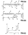
- a continuous line 10 is provided, on which a solar collector device 12 is arranged.
- the solar collector device 12 is formed for example by a plurality of trough collectors 14, which are arranged in series. In the flow through this trough collectors 14 by heat transfer medium concentrated solar radiation is directed to corresponding absorber tubes and in the absorber tubes flowing heat transfer medium is heated.
- the passage 10 comprises an evaporator region 16, in which after a corresponding preheating liquid heat transfer medium is vaporized solar.
- the evaporator region 16 is adjoined by a superheater region 18, at which steam generated in the evaporator region 16 is superheated. From the superheater area 18 exiting superheated heat transfer medium is fed to a turbine 20.
- FIG. 1 (c) schematically the temperature profile over the length I along the passage 10 is shown.
- a beginning of the passage is designated 21.
- a preheating area 22 in which an increase in temperature, initially adjoins the beginning 21 and in particular at least approximately linear temperature increase takes place.
- the evaporator region 16 in which the evaporation takes place.
- the temperature is at least approximately independent of location.
- the evaporator region 16 ends with an evaporation end point 24.
- the heat transfer medium absorbs sensible heat.
- the evaporator section 16 it absorbs latent heat.
- the superheater area 18 follows the evaporation end point 24.
- the vaporous heat transfer medium absorbs sensible heat.
- the flow path 10 is a direct evaporation.
- the introduced into the flow path 10 liquid heat transfer medium is preheated along the flow path 10 solar, evaporated and superheated.
- the superheated steam is provided to the turbine 20.
- the solar energy input fluctuates. This changes in the flow concept, as it is based on the FIG. 1 (a) is explained, the location of the evaporation end point 24. This is in FIG. 1 (a) indicated by the double arrow with the reference numeral 26.
- the oscillation initially arises in the axial direction (in a direction parallel to the longitudinal direction of the passage 10) and as a result also arise oscillating temperature gradients in the radial and tangential direction , These temperature gradients in turn cause thermal stresses in the material of the tube 28. This reduces the fatigue strength of the affected components.
- a passage 30 is divided into an evaporator section 32 and a superheater line 34.
- a separator 36 is arranged between the evaporator section 32 and the superheater line 34.
- An exit of the evaporator strand 32 leads into the separator 36.
- the superheater line 34 is continued.
- Another output of the separator 36 is fluidly connected to a line 38.
- This line 38 in turn is fluidly connected to a beginning 40 of the evaporation strand 32.
- a pump 42 is preferably arranged.
- the line 38 forms a recirculation line through which liquid heat transfer medium is recirculated from an exit of the evaporation strand 32 to the beginning 40.
- the evaporation end point is set to a certain extent in terms of hardware.
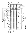
- a first embodiment of a solar thermal power plant according to the invention which in FIG. 2 and designated 44, includes a steam generating stage 45 having a plurality of parallel passages 46 (46a, 46b, etc.). This is followed by an evaporator region 50 with a solar collector device 52.
- the solar collector device 52 comprises, for example, a plurality of trough collectors.
- the evaporator region 50 is followed by a superheater region 54 in the passage 46. This is likewise arranged on the solar collector device 52. Between the evaporator section 50 and the superheater section 54 is the evaporation end point 56. This can be within a gutter collector. As will be explained in more detail below, it is the goal in the control method according to the invention, the evaporation end point 56 spatially, ie along the passage section 10, to fix and thereby determine the evaporation end 56 locally.
- a collecting device 58 connects to the superheater areas 54 of the passages 46. In this, the superheated steam of the collector strands of the parallel passages 46 is collected.
- the collector 58 which has inputs corresponding to the plurality of passages 46, is fluidly coupled to an output 60 at an output 60.
- the power block 62 includes (at least) a turbine and an electric current generator.
- a return line 64 leads to a distribution device, designated as a whole by 66, by means of which the flow of liquid heat transfer medium is distributed over the individual flow paths 46.
- the superheater area 54 is associated with a designated as a whole 68 68 injection device.
- liquid heat transfer medium can be injected into the superheater region 54 in order to be able to set an exit temperature of superheated steam from the superheater region 54. This will be explained in more detail below.
- the inlet temperature of superheated steam can be fixed in the power block 62.
- the injection device 68 comprises a control valve 70 assigned to the corresponding flow path 46.
- a control valve 70 By means of such a control valve 70, the quantity of the injected liquid heat transfer medium can be adjusted (including the possibility of setting that no liquid heat transfer medium is injected).
- the injection device 68 has at the respective passage 46 an injection point 72, which, as will be explained in more detail below, downstream temperature sensors, which provide temperature readings for carrying out the control method according to the invention, is arranged downstream.
- a branch 73 is arranged, from which a line 74 branches off, with which in turn the control valves 70 of the respective flow paths 46 are fluidly connected.
- the branch 73 liquid heat transfer medium can be decoupled and used for injection into the superheater regions 54 of the flow paths 46.
- a pump 76 for conveying the heat transfer medium is arranged.
- the solar thermal power plant 44 includes a control device 78. By means of such a regulation that the evaporation end 56 is fixed locally.
- a first temperature sensor 80 is arranged. This measures the temperature in the vaporous heat transfer medium.
- the first temperature sensor 80 is arranged outside a preheating region.
- a second temperature sensor 82 and a third temperature sensor 84 are arranged at a distance from one another.
- the corresponding distance is in FIG. 2 denoted by L. This distance can be greater than, equal to or less than the length of a trough collector, for example.
- the second temperature sensor 82 and the third temperature sensor 84 are arranged in front of the injection point 72 in a passage 46 with respect to the flow direction of the heat transfer medium.
- the first temperature sensor 80, the second temperature sensor 82 and the third temperature sensor 84 are signal-effectively connected to the control device 78.
- the corresponding temperature measurements (T 1 , T 2 and T 3 ) of these temperature sensors are transferred to the control device 78 for further evaluation and processing.
- the control valves 48 of the flow path 46 form a mass flow control device 86. These control valves 48 allow adjustability of the mass flow in the respective flow paths 46.
- the control valves 48 are controlled by the control device 78, so that via the control device 78, the mass flow of heat transfer medium is adjustable.
- the control device 78 is, for example signal-effectively connected to the injector 68 and in particular their control valves 70.
- the control device 78 controls the control valves 70. It may be provided for the control of the superheater injection and a separate means of the control device 78 device.
- FIG. 2 the connections between the control device 78 and elements of the flow paths 46 are shown only for the passage 46a. The same connections exist for the other pass lines.
- superheated steam is produced as follows:
- Liquid heat transfer medium (in particular feed water) is divided between the individual parallel passages 46.
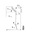
- heat transfer medium in a preheating area 88 (FIG. FIG. 4 ) preheated. In this area, the heat transfer medium absorbs substantially sensible heat.
- the preheating region 88 is adjoined by the evaporator region 50. In this area, the heat transfer medium absorbs substantially latent heat. There is an evaporation. In the superheater area 54 overheating occurs.
- the temperature T 1 is measured by the first temperature sensor 80 before the evaporation end point 56.
- the second temperature sensor 82 measures the corresponding temperature T 2 and the third temperature sensor 84 measures the temperature T 3 in the superheater area 54 after the evaporation end point 56.
- the temperature value T 1 is extrapolated to longer lengths I out and the gradient to smaller lengths out.
- the intersection is determined. This intersection corresponds to an actual value for the position of the evaporation end point 56.
- the distance to the desired value (reference variable), namely the predetermined position of the evaporation end point 56, is determined.
- the manipulated variable is, for example, a valve lift of the corresponding control valve 48. According to the deviation, in a continuous control process, the mass flow is reduced or increased in order to equalize the actual value to the desired value.
- the mass flow at each flow path 46 is set on the basis of the determined temperature gradient .DELTA.T / L and the measured temperature T 1 to fix the evaporation end point 56 locally. This local fixation is a kind of "software fixation".
- FIG. 4 schematically with the reference numeral 90a, a first case with high irradiation and the reference numeral 90b, a second case with low irradiation in the temperature profile over the length I shown.
- the lower irradiation case (90b) has a longer preheat area.
- the gradient in superheater area 54 is smaller than for case 90a. This requires for case 90b, as compared to case 90a, to decrease the mass flow in the corresponding flow path 46.
- the control device 78 also controls the injector 68.
- the aim is to adjust at an output 92 of the passage 46 and thus at the output of the superheater area 54 a certain temperature (adapted to the turbine of the power block 62) and also to fix. This can be carried out by controlled injection of a certain amount of liquid heat transfer medium.
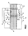
- a second embodiment of a solar thermal power plant according to the invention which in FIG. 3 shown schematically and designated there by 94, is basically the same structure as the solar thermal power plant 44. For the same elements like reference numerals are used.
- An additional injection device 96 is provided, through which liquid heat transfer medium can be injected into the evaporator region 50.
- an injection point 98 in the evaporator region 50 is arranged following the first temperature sensor 80 at the respective flow paths 46, ie the respective injection point 98 lies between the first temperature sensor 80 and the evaporation end point 56.
- the injection device for example, has a control valve 100 assigned to each passage 46.
- the control valves 100 are fluidly connected to the return line 64.
- a branch 102 leads from a branch 102 to the control valves 100 of the flow paths 46.
- the branch 102 in turn is arranged, for example, on the return line 64 or on the line 74.
- the control device 78 controls the injector 96 with the control valves 100.
- the injector 96 forms a mass flow control device. Through them, the mass flow of heat transfer medium in the flow path 46 can be influenced.
- the control valves 48 then form a first mass flow control device 86 and the injection device 96 forms a second mass flow control device 106.
- the control quality can be improved and increase the control speed.
- the evaporation end point 56 can be locally fixed by a control method in order to minimize oscillations of the evaporation end point 56 with fluctuating solar energy input.
- the parallel flow paths are collector strands. For each collector train (for each pass line 46), the evaporation end point 56 is fixed.
- an actual value for the evaporation end point is determined in order to control to the desired value (reference variable).
- Regulated is the mass flow of heat transfer medium in the respective collector strand, d. H. in the respective passage 60.
- the mass flow is realized by adjusting the injected into the respective passage 60 amount of liquid heat transfer medium. This is done primarily via the first mass flow control device 46 with the control valves 48.
- a second mass flow control device 106 may be provided with the control valves 100.
- the measured temperature T 1 for determining the actual value for the evaporation end point is additionally determined. This results in a stable control and in real operation, the fluctuation range of the evaporation end 56 can be limited to a very small range.
- the control quality can be improved and the control speed can be greatly increased.
- the solution according to the invention can be implemented more cost-effectively than a solution according to the recirculation concept. In addition, lower heat losses of the entire system occur. It is basically possible to "adjust" the local position of the evaporation end point 56 "software" and, for example, to move closer to the beginning of a collector string. It results in low material loads and thus a longer possible plant operation with improved controllability.
Landscapes
- Engineering & Computer Science (AREA)
- Physics & Mathematics (AREA)
- Thermal Sciences (AREA)
- Mechanical Engineering (AREA)
- General Engineering & Computer Science (AREA)
- Life Sciences & Earth Sciences (AREA)
- Sustainable Energy (AREA)
- Sustainable Development (AREA)
- Engine Equipment That Uses Special Cycles (AREA)
Claims (15)
- Procédé servant à produire de la vapeur surchauffée dans une centrale héliothermique, dans le cadre duquel de la vapeur est produite sur un tronçon de passage pour milieu caloporteur sous l'effet de l'énergie solaire dans une zone d'évaporation et la vapeur est surchauffée dans une zone de surchauffe sous l'effet de l'énergie solaire, un point final d'évaporation de la zone d'évaporation étant fixé de manière locale selon un procédé de régulation, dans le cadre duquel sont déterminés un gradient de température spatial dans la zone de surchauffe et une température dans la zone d'évaporation et le débit massique en milieu caloporteur est réglé sur le tronçon de passage en fonction du gradient de température dans la zone de surchauffe et en fonction de la température mesurée dans la zone d'évaporation.
- Procédé selon la revendication 1, caractérisé en ce que le débit massique du milieu caloporteur est réglé sur le tronçon de passage pour fixer le point terminal d'évaporation.
- Procédé selon la revendication 1 ou 2, caractérisé en ce qu'une grandeur de régulation est, dans le procédé de régulation, la position spatiale du point terminal d'évaporation, une grandeur de référence étant un lieu défini.
- Procédé selon l'une quelconque des revendications précédentes, caractérisé en ce qu'une grandeur d'ajustage détermine, dans le procédé de régulation, le débit massique du milieu caloporteur sur le tronçon de passage.
- Procédé selon l'une quelconque des revendications précédentes, caractérisé en ce que le gradient de température et la température mesurée sont, dans le procédé de régulation, extrapolés dans la zone d'évaporation sur un point d'intersection spatial, et en ce qu'une ou plusieurs grandeurs d'ajustage sont déterminées par une position spatiale prédéfinie du point terminal d'évaporation du fait d'une déviation du point d'intersection.
- Procédé selon l'une quelconque des revendications précédentes, caractérisé en ce que la température est mesurée dans la zone d'évaporation en dehors d'une zone de préchauffage.
- Procédé selon l'une quelconque des revendications précédentes, caractérisé en ce que le gradient de température est calculé à partir des températures mesurées au niveau au moins de deux endroits espacés dans la zone de surchauffe.
- Procédé selon l'une quelconque des revendications précédentes, caractérisé en ce qu'on injecte de manière régulée un milieu caloporteur fluide dans la zone d'évaporation, et en particulier en ce que l'injection est effectuée entre le point de mesure de la température et le point terminal d'évaporation.
- Procédé selon l'une quelconque des revendications précédentes, caractérisé en ce qu'une température de sortie est régulée au niveau de la zone de surchauffe sur une valeur constante, et en particulier en ce qu'un milieu caloporteur fluide est injecté de manière régulée dans la zone de surchauffe.
- Centrale héliothermique comprenant un étage de production de vapeur (45), comprenant au moins une branche de collecte dotée d'un tronçon de passage (46) pour le milieu caloporteur avec une zone d'évaporation (50) et avec une zone de surchauffe (54), un premier capteur de température (80) qui est disposé au niveau de la zone d'évaporation (50), un deuxième capteur de température (82) et un troisième capteur de température (84), lesquels sont disposés de manière espacée les uns par rapport aux autres au niveau de la zone de surchauffe (54), un système de régulation de débit massique (86 ; 106), lequel permet de régler le débit massique en milieu caloporteur sur le tronçon de passage (46), et un système de régulation (78) qui est relié de manière efficace en termes de signal au premier capteur de température (80), au deuxième capteur de température (82) et au troisième capteur de température (84) et qui détermine à partir d'une deuxième température (T2) et d'une troisième température (T3) un gradient de température spatial (ΔT/L) et qui commande le système de régulation de débit massique (86 ; 106) servant à fixer un point terminal d'évaporation (56).
- Centrale héliothermique selon la revendication 10, caractérisée en ce qu'une soupape de régulation (48) est disposée en début de tronçon de passage (46), laquelle est commandée par le système de régulation (78).
- Centrale héliothermique selon la revendication 10 ou 11, caractérisée par un système d'injection (96) servant à injecter un milieu caloporteur fluide avec au moins un point d'injection (98) dans la zone d'évaporation (50), et caractérisée en particulier en ce que le système d'injection (96) est commandé par le système de régulation (78), et en particulier en ce que le système d'injection (96) comprend une soupape de régulation (100), et en particulier en ce que l'au moins un point d'injection (98) du système d'injection (96) se trouve entre un point de mesure de température du premier capteur de température (80) et le point terminal d'évaporation (56).
- Centrale héliothermique selon l'une quelconque des revendications 10 à 12, caractérisée par un système d'injection (68) servant à injecter un milieu caloporteur fluide avec au moins un point d'injection (72) dans la zone de surchauffe (54).
- Centrale héliothermique selon l'une quelconque des revendications 10 à 13, caractérisée par un système de collecte (52) solaire, au niveau duquel est disposé le tronçon de passage (46).
- Centrale héliothermique selon l'une quelconque des revendications 10 à 14, caractérisée en ce que l'étage de production de vapeur (45) est relié de manière fluidiquement efficace à au moins une turbine.
Applications Claiming Priority (2)
| Application Number | Priority Date | Filing Date | Title |
|---|---|---|---|
| DE102009025455A DE102009025455A1 (de) | 2009-06-15 | 2009-06-15 | Verfahren zur Erzeugung von überhitztem Dampf an einem solarthermischen Kraftwerk und solarthermisches Kraftwerk |
| PCT/EP2010/057982 WO2010145970A2 (fr) | 2009-06-15 | 2010-06-08 | Procédé de production de vapeur surchauffée dans une centrale héliothermique et centrale héliothermique |
Publications (2)
| Publication Number | Publication Date |
|---|---|
| EP2454523A2 EP2454523A2 (fr) | 2012-05-23 |
| EP2454523B1 true EP2454523B1 (fr) | 2013-11-06 |
Family
ID=43298801
Family Applications (1)
| Application Number | Title | Priority Date | Filing Date |
|---|---|---|---|
| EP10722127.7A Not-in-force EP2454523B1 (fr) | 2009-06-15 | 2010-06-08 | Procédé de production de vapeur surchauffée dans une centrale héliothermique et centrale héliothermique |
Country Status (6)
| Country | Link |
|---|---|
| US (1) | US20120144831A1 (fr) |
| EP (1) | EP2454523B1 (fr) |
| DE (1) | DE102009025455A1 (fr) |
| ES (1) | ES2445529T3 (fr) |
| IL (1) | IL216959A0 (fr) |
| WO (1) | WO2010145970A2 (fr) |
Families Citing this family (15)
| Publication number | Priority date | Publication date | Assignee | Title |
|---|---|---|---|---|
| DE102011004264A1 (de) * | 2011-02-17 | 2012-08-23 | Siemens Aktiengesellschaft | Solarthermischer Dampferzeuger |
| WO2013002054A1 (fr) * | 2011-06-30 | 2013-01-03 | バブコック日立株式会社 | Chaudière à chaleur solaire et centrale électrique à chaleur solaire |
| WO2013014685A1 (fr) * | 2011-07-28 | 2013-01-31 | Su.Co.Sys. S.R.L. | Installation de cogénération thermique |
| DE102011081920A1 (de) * | 2011-08-31 | 2013-02-28 | Johannes Fürst zu Waldburg-Wolfegg und Waldsee | Solarthermisches Kraftwerk |
| DE102012103457B4 (de) | 2011-12-12 | 2018-02-15 | Deutsches Zentrum für Luft- und Raumfahrt e.V. | Verfahren zum Betreiben eines solarthermischen Kraftwerkes |
| DE102011056796B4 (de) * | 2011-12-21 | 2017-03-02 | Flagsol Gmbh | Solarthermisches Kraftwerk und Verfahren zur Regelung des Wärmeträgermediummassenstroms |
| DE102012101249A1 (de) * | 2012-02-16 | 2013-08-22 | Deutsches Zentrum für Luft- und Raumfahrt e.V. | Solarthermisches Kraftwerk und Verfahren zum Betreiben eines solarthermischen Kraftwerks |
| ES2658567T3 (es) * | 2012-07-17 | 2018-03-12 | Mitsubishi Hitachi Power Systems, Ltd. | Sistema de energía solar |
| DE102012107353B4 (de) * | 2012-08-10 | 2015-05-07 | Deutsches Zentrum für Luft- und Raumfahrt e.V. | Solarthermisches Kraftwerk und Verfahren zum Betreiben eines solarthermischen Kraftwerks |
| US20140182579A1 (en) * | 2012-09-18 | 2014-07-03 | David George Allen | Solar energy collection conduit |
| DE102012111775B4 (de) | 2012-12-04 | 2016-08-04 | Deutsches Zentrum für Luft- und Raumfahrt e.V. | Solarthermische Dampferzeugungsstufe, solarthermisches Kraftwerk und Verfahren zum Betreiben einer solarthermischen Dampferzeugungsstufe |
| CN103115445B (zh) * | 2013-02-05 | 2014-09-24 | 中盈长江国际新能源投资有限公司 | 太阳能自动均热聚热管、槽式组件、热发电系统和工艺 |
| WO2014148259A1 (fr) * | 2013-03-18 | 2014-09-25 | バブコック日立株式会社 | Système de collecte de chaleur solaire |
| US9605879B2 (en) * | 2013-11-08 | 2017-03-28 | Alstom Technology Ltd. | System and method for controlling molten salt temperature |
| AU2019100755B4 (en) * | 2019-02-13 | 2020-02-13 | WORTHINGTON, Richard John DR | A multi-chamber solar collector |
Family Cites Families (9)
| Publication number | Priority date | Publication date | Assignee | Title |
|---|---|---|---|---|
| US4289114A (en) * | 1978-09-12 | 1981-09-15 | The Babcock & Wilcox Company | Control system for a solar steam generator |
| US4583374A (en) * | 1983-10-21 | 1986-04-22 | Veb Kombinat Luft-Und Kaltetechnik | Temperature and liquid level control system for fluid cycles |
| US6536677B2 (en) * | 2000-06-08 | 2003-03-25 | University Of Puerto Rico | Automation and control of solar air conditioning systems |
| EP1262638A1 (fr) * | 2001-05-31 | 2002-12-04 | Siemens Aktiengesellschaft | Dispositif pour refroidir le fluide de refroidissement d'une turbine à gaz et installation à turbine à gaz et à vapeur avec un tel dispositif |
| DE10152968C1 (de) | 2001-10-19 | 2003-04-30 | Deutsch Zentr Luft & Raumfahrt | Solarthermisches Kraftwerk und Verfahren zum Betreiben eines solarthermischen Kraftwerks |
| EP1512907A1 (fr) * | 2003-09-03 | 2005-03-09 | Siemens Aktiengesellschaft | Procédé pour le demarrage d'un générateur de vapeur à passage unique et le générateur de vapeur à passage unique pour la mise en oeuvre du procédé |
| DE102006021972B4 (de) * | 2006-05-03 | 2012-01-12 | Deutsches Zentrum für Luft- und Raumfahrt e.V. | Solarthermisches Kraftwerk und Verfahren zur Umwandlung von thermischer Energie in elektrische/mechanische Energie |
| DE102007005562A1 (de) * | 2007-01-24 | 2008-08-07 | Deutsches Zentrum für Luft- und Raumfahrt e.V. | Verfahren zum Betreiben eines solarthermischen Kraftwerks und solarthermisches Kraftwerk |
| DE102007052234A1 (de) | 2007-10-22 | 2009-04-23 | Deutsches Zentrum für Luft- und Raumfahrt e.V. | Verfahren zum Betreiben eines solarthermischen Kraftwerks und solarthermisches Kraftwerk |
-
2009
- 2009-06-15 DE DE102009025455A patent/DE102009025455A1/de not_active Withdrawn
-
2010
- 2010-06-08 ES ES10722127.7T patent/ES2445529T3/es active Active
- 2010-06-08 WO PCT/EP2010/057982 patent/WO2010145970A2/fr not_active Ceased
- 2010-06-08 EP EP10722127.7A patent/EP2454523B1/fr not_active Not-in-force
-
2011
- 2011-12-13 IL IL216959A patent/IL216959A0/en unknown
- 2011-12-14 US US13/325,407 patent/US20120144831A1/en not_active Abandoned
Also Published As
| Publication number | Publication date |
|---|---|
| EP2454523A2 (fr) | 2012-05-23 |
| US20120144831A1 (en) | 2012-06-14 |
| IL216959A0 (en) | 2012-06-28 |
| DE102009025455A1 (de) | 2011-01-05 |
| WO2010145970A3 (fr) | 2012-08-23 |
| ES2445529T3 (es) | 2014-03-03 |
| WO2010145970A2 (fr) | 2010-12-23 |
Similar Documents
| Publication | Publication Date | Title |
|---|---|---|
| EP2454523B1 (fr) | Procédé de production de vapeur surchauffée dans une centrale héliothermique et centrale héliothermique | |
| EP2053242A2 (fr) | Procédé de fonctionnement d'une centrale thermique solaire et centrale thermique solaire | |
| EP1998109A2 (fr) | Procédé de fonctionnement d'une installation de chaleur industrielle thermique solaire et installation de chaleur industrielle thermique solaire | |
| EP0436536B1 (fr) | Procede et installation de generation de vapeur au moyen de chaleur perdue | |
| DE10329623B3 (de) | Verfahren zur solarthermischen Gewinnung elektrischer Energie und solarthermisches Kraftwerk | |
| DE10144841C1 (de) | Solarthermisches Gas- und Dampfkraftwerk und Verfahren zur Umwandlung von thermischer Energie in elektrische Energie | |
| DE10025472C2 (de) | Dampfphasenlötanlage mit überhitztem Dampf | |
| DE10152971C1 (de) | Solarthermisches Kraftwerk und Regelungsverfahren für ein solarthermisches Kraftwerk | |
| DE102012103457B4 (de) | Verfahren zum Betreiben eines solarthermischen Kraftwerkes | |
| EP3109466A1 (fr) | Pale de rotor d'éolienne dotée d'un dispositif de chauffage électrique | |
| WO2013120740A2 (fr) | Centrale héliothermique et procédé pour faire fonctionner une centrale héliothermique | |
| EP2676072B1 (fr) | Procédé pour faire fonctionner un générateur de vapeur à circulation ouverte | |
| DE102012111775B4 (de) | Solarthermische Dampferzeugungsstufe, solarthermisches Kraftwerk und Verfahren zum Betreiben einer solarthermischen Dampferzeugungsstufe | |
| DE102006021972B4 (de) | Solarthermisches Kraftwerk und Verfahren zur Umwandlung von thermischer Energie in elektrische/mechanische Energie | |
| DE102012107353B4 (de) | Solarthermisches Kraftwerk und Verfahren zum Betreiben eines solarthermischen Kraftwerks | |
| CH642155A5 (de) | Dampferzeuger mit zwischenwand zwischen zwei brennkammern. | |
| DE2006409C3 (de) | Im Gleitdruckverfahren betriebener Zwanglaufdampferzeuger | |
| DE102012102115A1 (de) | Solarthermisches Kraftwerk und Verfahren zum Betreiben eines solarthermischen Kraftwerks | |
| CH676630A5 (fr) | ||
| DE1965078B2 (de) | Verfahren zum gleitdruckbetrieb eines zwanglaufdampferzeu gers | |
| DE102011056796B4 (de) | Solarthermisches Kraftwerk und Verfahren zur Regelung des Wärmeträgermediummassenstroms | |
| EP2655811B1 (fr) | Procédé pour ajuster une augmentation de puissance de courte durée d'une turbine à vapeur | |
| DE1965078C (de) | Verfahren zum Gleitdruckbetrieb eines Zwanglauf da mpferzeugers | |
| EP0856125A2 (fr) | Procede et dispositif de production de vapeur solaire | |
| EP2825736B1 (fr) | Procédé et dispositif pour faire fonctionner une centrale héliothermique |
Legal Events
| Date | Code | Title | Description |
|---|---|---|---|
| PUAI | Public reference made under article 153(3) epc to a published international application that has entered the european phase |
Free format text: ORIGINAL CODE: 0009012 |
|
| 17P | Request for examination filed |
Effective date: 20120112 |
|
| AK | Designated contracting states |
Kind code of ref document: A2 Designated state(s): AL AT BE BG CH CY CZ DE DK EE ES FI FR GB GR HR HU IE IS IT LI LT LU LV MC MK MT NL NO PL PT RO SE SI SK SM TR |
|
| DAX | Request for extension of the european patent (deleted) | ||
| R17D | Deferred search report published (corrected) |
Effective date: 20120823 |
|
| GRAP | Despatch of communication of intention to grant a patent |
Free format text: ORIGINAL CODE: EPIDOSNIGR1 |
|
| RIC1 | Information provided on ipc code assigned before grant |
Ipc: F22B 1/00 20060101ALI20130419BHEP Ipc: F22B 29/08 20060101AFI20130419BHEP |
|
| INTG | Intention to grant announced |
Effective date: 20130524 |
|
| GRAS | Grant fee paid |
Free format text: ORIGINAL CODE: EPIDOSNIGR3 |
|
| GRAA | (expected) grant |
Free format text: ORIGINAL CODE: 0009210 |
|
| AK | Designated contracting states |
Kind code of ref document: B1 Designated state(s): AL AT BE BG CH CY CZ DE DK EE ES FI FR GB GR HR HU IE IS IT LI LT LU LV MC MK MT NL NO PL PT RO SE SI SK SM TR |
|
| REG | Reference to a national code |
Ref country code: GB Ref legal event code: FG4D Free format text: NOT ENGLISH |
|
| REG | Reference to a national code |
Ref country code: CH Ref legal event code: EP |
|
| REG | Reference to a national code |
Ref country code: AT Ref legal event code: REF Ref document number: 639753 Country of ref document: AT Kind code of ref document: T Effective date: 20131215 |
|
| REG | Reference to a national code |
Ref country code: IE Ref legal event code: FG4D Free format text: LANGUAGE OF EP DOCUMENT: GERMAN |
|
| REG | Reference to a national code |
Ref country code: DE Ref legal event code: R096 Ref document number: 502010005289 Country of ref document: DE Effective date: 20140102 |
|
| REG | Reference to a national code |
Ref country code: ES Ref legal event code: FG2A Ref document number: 2445529 Country of ref document: ES Kind code of ref document: T3 Effective date: 20140303 |
|
| REG | Reference to a national code |
Ref country code: NL Ref legal event code: VDEP Effective date: 20131106 |
|
| REG | Reference to a national code |
Ref country code: LT Ref legal event code: MG4D |
|
| PG25 | Lapsed in a contracting state [announced via postgrant information from national office to epo] |
Ref country code: LT Free format text: LAPSE BECAUSE OF FAILURE TO SUBMIT A TRANSLATION OF THE DESCRIPTION OR TO PAY THE FEE WITHIN THE PRESCRIBED TIME-LIMIT Effective date: 20131106 Ref country code: NL Free format text: LAPSE BECAUSE OF FAILURE TO SUBMIT A TRANSLATION OF THE DESCRIPTION OR TO PAY THE FEE WITHIN THE PRESCRIBED TIME-LIMIT Effective date: 20131106 Ref country code: NO Free format text: LAPSE BECAUSE OF FAILURE TO SUBMIT A TRANSLATION OF THE DESCRIPTION OR TO PAY THE FEE WITHIN THE PRESCRIBED TIME-LIMIT Effective date: 20140206 Ref country code: FI Free format text: LAPSE BECAUSE OF FAILURE TO SUBMIT A TRANSLATION OF THE DESCRIPTION OR TO PAY THE FEE WITHIN THE PRESCRIBED TIME-LIMIT Effective date: 20131106 Ref country code: SE Free format text: LAPSE BECAUSE OF FAILURE TO SUBMIT A TRANSLATION OF THE DESCRIPTION OR TO PAY THE FEE WITHIN THE PRESCRIBED TIME-LIMIT Effective date: 20131106 Ref country code: HR Free format text: LAPSE BECAUSE OF FAILURE TO SUBMIT A TRANSLATION OF THE DESCRIPTION OR TO PAY THE FEE WITHIN THE PRESCRIBED TIME-LIMIT Effective date: 20131106 Ref country code: IS Free format text: LAPSE BECAUSE OF FAILURE TO SUBMIT A TRANSLATION OF THE DESCRIPTION OR TO PAY THE FEE WITHIN THE PRESCRIBED TIME-LIMIT Effective date: 20140306 |
|
| PG25 | Lapsed in a contracting state [announced via postgrant information from national office to epo] |
Ref country code: LV Free format text: LAPSE BECAUSE OF FAILURE TO SUBMIT A TRANSLATION OF THE DESCRIPTION OR TO PAY THE FEE WITHIN THE PRESCRIBED TIME-LIMIT Effective date: 20131106 |
|
| PG25 | Lapsed in a contracting state [announced via postgrant information from national office to epo] |
Ref country code: PT Free format text: LAPSE BECAUSE OF FAILURE TO SUBMIT A TRANSLATION OF THE DESCRIPTION OR TO PAY THE FEE WITHIN THE PRESCRIBED TIME-LIMIT Effective date: 20140306 |
|
| PG25 | Lapsed in a contracting state [announced via postgrant information from national office to epo] |
Ref country code: EE Free format text: LAPSE BECAUSE OF FAILURE TO SUBMIT A TRANSLATION OF THE DESCRIPTION OR TO PAY THE FEE WITHIN THE PRESCRIBED TIME-LIMIT Effective date: 20131106 |
|
| REG | Reference to a national code |
Ref country code: DE Ref legal event code: R097 Ref document number: 502010005289 Country of ref document: DE |
|
| PG25 | Lapsed in a contracting state [announced via postgrant information from national office to epo] |
Ref country code: PL Free format text: LAPSE BECAUSE OF FAILURE TO SUBMIT A TRANSLATION OF THE DESCRIPTION OR TO PAY THE FEE WITHIN THE PRESCRIBED TIME-LIMIT Effective date: 20131106 Ref country code: CZ Free format text: LAPSE BECAUSE OF FAILURE TO SUBMIT A TRANSLATION OF THE DESCRIPTION OR TO PAY THE FEE WITHIN THE PRESCRIBED TIME-LIMIT Effective date: 20131106 Ref country code: RO Free format text: LAPSE BECAUSE OF FAILURE TO SUBMIT A TRANSLATION OF THE DESCRIPTION OR TO PAY THE FEE WITHIN THE PRESCRIBED TIME-LIMIT Effective date: 20131106 Ref country code: SK Free format text: LAPSE BECAUSE OF FAILURE TO SUBMIT A TRANSLATION OF THE DESCRIPTION OR TO PAY THE FEE WITHIN THE PRESCRIBED TIME-LIMIT Effective date: 20131106 |
|
| PLBE | No opposition filed within time limit |
Free format text: ORIGINAL CODE: 0009261 |
|
| STAA | Information on the status of an ep patent application or granted ep patent |
Free format text: STATUS: NO OPPOSITION FILED WITHIN TIME LIMIT |
|
| PG25 | Lapsed in a contracting state [announced via postgrant information from national office to epo] |
Ref country code: DK Free format text: LAPSE BECAUSE OF FAILURE TO SUBMIT A TRANSLATION OF THE DESCRIPTION OR TO PAY THE FEE WITHIN THE PRESCRIBED TIME-LIMIT Effective date: 20131106 |
|
| 26N | No opposition filed |
Effective date: 20140807 |
|
| REG | Reference to a national code |
Ref country code: DE Ref legal event code: R097 Ref document number: 502010005289 Country of ref document: DE Effective date: 20140807 |
|
| PG25 | Lapsed in a contracting state [announced via postgrant information from national office to epo] |
Ref country code: LU Free format text: LAPSE BECAUSE OF FAILURE TO SUBMIT A TRANSLATION OF THE DESCRIPTION OR TO PAY THE FEE WITHIN THE PRESCRIBED TIME-LIMIT Effective date: 20140608 Ref country code: MC Free format text: LAPSE BECAUSE OF FAILURE TO SUBMIT A TRANSLATION OF THE DESCRIPTION OR TO PAY THE FEE WITHIN THE PRESCRIBED TIME-LIMIT Effective date: 20131106 |
|
| REG | Reference to a national code |
Ref country code: CH Ref legal event code: PL |
|
| GBPC | Gb: european patent ceased through non-payment of renewal fee |
Effective date: 20140608 |
|
| PG25 | Lapsed in a contracting state [announced via postgrant information from national office to epo] |
Ref country code: SI Free format text: LAPSE BECAUSE OF FAILURE TO SUBMIT A TRANSLATION OF THE DESCRIPTION OR TO PAY THE FEE WITHIN THE PRESCRIBED TIME-LIMIT Effective date: 20131106 |
|
| REG | Reference to a national code |
Ref country code: IE Ref legal event code: MM4A |
|
| PG25 | Lapsed in a contracting state [announced via postgrant information from national office to epo] |
Ref country code: IE Free format text: LAPSE BECAUSE OF NON-PAYMENT OF DUE FEES Effective date: 20140608 Ref country code: LI Free format text: LAPSE BECAUSE OF NON-PAYMENT OF DUE FEES Effective date: 20140630 Ref country code: CH Free format text: LAPSE BECAUSE OF NON-PAYMENT OF DUE FEES Effective date: 20140630 |
|
| PG25 | Lapsed in a contracting state [announced via postgrant information from national office to epo] |
Ref country code: GB Free format text: LAPSE BECAUSE OF NON-PAYMENT OF DUE FEES Effective date: 20140608 |
|
| REG | Reference to a national code |
Ref country code: DE Ref legal event code: R082 Ref document number: 502010005289 Country of ref document: DE Representative=s name: HOEGER, STELLRECHT & PARTNER PATENTANWAELTE MB, DE |
|
| PG25 | Lapsed in a contracting state [announced via postgrant information from national office to epo] |
Ref country code: MT Free format text: LAPSE BECAUSE OF FAILURE TO SUBMIT A TRANSLATION OF THE DESCRIPTION OR TO PAY THE FEE WITHIN THE PRESCRIBED TIME-LIMIT Effective date: 20131106 |
|
| PG25 | Lapsed in a contracting state [announced via postgrant information from national office to epo] |
Ref country code: SM Free format text: LAPSE BECAUSE OF FAILURE TO SUBMIT A TRANSLATION OF THE DESCRIPTION OR TO PAY THE FEE WITHIN THE PRESCRIBED TIME-LIMIT Effective date: 20131106 |
|
| REG | Reference to a national code |
Ref country code: FR Ref legal event code: PLFP Year of fee payment: 7 |
|
| PG25 | Lapsed in a contracting state [announced via postgrant information from national office to epo] |
Ref country code: CY Free format text: LAPSE BECAUSE OF FAILURE TO SUBMIT A TRANSLATION OF THE DESCRIPTION OR TO PAY THE FEE WITHIN THE PRESCRIBED TIME-LIMIT Effective date: 20131106 Ref country code: BG Free format text: LAPSE BECAUSE OF FAILURE TO SUBMIT A TRANSLATION OF THE DESCRIPTION OR TO PAY THE FEE WITHIN THE PRESCRIBED TIME-LIMIT Effective date: 20131106 Ref country code: GR Free format text: LAPSE BECAUSE OF FAILURE TO SUBMIT A TRANSLATION OF THE DESCRIPTION OR TO PAY THE FEE WITHIN THE PRESCRIBED TIME-LIMIT Effective date: 20140207 |
|
| PG25 | Lapsed in a contracting state [announced via postgrant information from national office to epo] |
Ref country code: BE Free format text: LAPSE BECAUSE OF FAILURE TO SUBMIT A TRANSLATION OF THE DESCRIPTION OR TO PAY THE FEE WITHIN THE PRESCRIBED TIME-LIMIT Effective date: 20140630 Ref country code: TR Free format text: LAPSE BECAUSE OF FAILURE TO SUBMIT A TRANSLATION OF THE DESCRIPTION OR TO PAY THE FEE WITHIN THE PRESCRIBED TIME-LIMIT Effective date: 20131106 Ref country code: HU Free format text: LAPSE BECAUSE OF FAILURE TO SUBMIT A TRANSLATION OF THE DESCRIPTION OR TO PAY THE FEE WITHIN THE PRESCRIBED TIME-LIMIT; INVALID AB INITIO Effective date: 20100608 |
|
| REG | Reference to a national code |
Ref country code: AT Ref legal event code: MM01 Ref document number: 639753 Country of ref document: AT Kind code of ref document: T Effective date: 20150608 |
|
| PG25 | Lapsed in a contracting state [announced via postgrant information from national office to epo] |
Ref country code: AT Free format text: LAPSE BECAUSE OF NON-PAYMENT OF DUE FEES Effective date: 20150608 |
|
| REG | Reference to a national code |
Ref country code: FR Ref legal event code: PLFP Year of fee payment: 8 |
|
| REG | Reference to a national code |
Ref country code: FR Ref legal event code: PLFP Year of fee payment: 9 |
|
| PG25 | Lapsed in a contracting state [announced via postgrant information from national office to epo] |
Ref country code: MK Free format text: LAPSE BECAUSE OF FAILURE TO SUBMIT A TRANSLATION OF THE DESCRIPTION OR TO PAY THE FEE WITHIN THE PRESCRIBED TIME-LIMIT Effective date: 20131106 |
|
| PG25 | Lapsed in a contracting state [announced via postgrant information from national office to epo] |
Ref country code: AL Free format text: LAPSE BECAUSE OF FAILURE TO SUBMIT A TRANSLATION OF THE DESCRIPTION OR TO PAY THE FEE WITHIN THE PRESCRIBED TIME-LIMIT Effective date: 20131106 |
|
| REG | Reference to a national code |
Ref country code: DE Ref legal event code: R082 Ref document number: 502010005289 Country of ref document: DE Representative=s name: HOEGER, STELLRECHT & PARTNER PATENTANWAELTE MB, DE |
|
| PGFP | Annual fee paid to national office [announced via postgrant information from national office to epo] |
Ref country code: IT Payment date: 20220623 Year of fee payment: 13 Ref country code: FR Payment date: 20220517 Year of fee payment: 13 Ref country code: DE Payment date: 20220512 Year of fee payment: 13 |
|
| PGFP | Annual fee paid to national office [announced via postgrant information from national office to epo] |
Ref country code: ES Payment date: 20220708 Year of fee payment: 13 |
|
| REG | Reference to a national code |
Ref country code: DE Ref legal event code: R119 Ref document number: 502010005289 Country of ref document: DE |
|
| PG25 | Lapsed in a contracting state [announced via postgrant information from national office to epo] |
Ref country code: DE Free format text: LAPSE BECAUSE OF NON-PAYMENT OF DUE FEES Effective date: 20240103 |
|
| PG25 | Lapsed in a contracting state [announced via postgrant information from national office to epo] |
Ref country code: FR Free format text: LAPSE BECAUSE OF NON-PAYMENT OF DUE FEES Effective date: 20230630 |
|
| REG | Reference to a national code |
Ref country code: ES Ref legal event code: FD2A Effective date: 20240729 |
|
| PG25 | Lapsed in a contracting state [announced via postgrant information from national office to epo] |
Ref country code: IT Free format text: LAPSE BECAUSE OF NON-PAYMENT OF DUE FEES Effective date: 20230608 |
|
| PG25 | Lapsed in a contracting state [announced via postgrant information from national office to epo] |
Ref country code: ES Free format text: LAPSE BECAUSE OF NON-PAYMENT OF DUE FEES Effective date: 20230609 |
|
| PG25 | Lapsed in a contracting state [announced via postgrant information from national office to epo] |
Ref country code: ES Free format text: LAPSE BECAUSE OF NON-PAYMENT OF DUE FEES Effective date: 20230609 |