EP1998109A2 - Procédé de fonctionnement d'une installation de chaleur industrielle thermique solaire et installation de chaleur industrielle thermique solaire - Google Patents
Procédé de fonctionnement d'une installation de chaleur industrielle thermique solaire et installation de chaleur industrielle thermique solaire Download PDFInfo
- Publication number
- EP1998109A2 EP1998109A2 EP08150509A EP08150509A EP1998109A2 EP 1998109 A2 EP1998109 A2 EP 1998109A2 EP 08150509 A EP08150509 A EP 08150509A EP 08150509 A EP08150509 A EP 08150509A EP 1998109 A2 EP1998109 A2 EP 1998109A2
- Authority
- EP
- European Patent Office
- Prior art keywords
- heating
- transfer medium
- heat transfer
- thermal process
- solar thermal
- Prior art date
- Legal status (The legal status is an assumption and is not a legal conclusion. Google has not performed a legal analysis and makes no representation as to the accuracy of the status listed.)
- Withdrawn
Links
Images


Classifications
-
- F—MECHANICAL ENGINEERING; LIGHTING; HEATING; WEAPONS; BLASTING
- F22—STEAM GENERATION
- F22B—METHODS OF STEAM GENERATION; STEAM BOILERS
- F22B35/00—Control systems for steam boilers
- F22B35/06—Control systems for steam boilers for steam boilers of forced-flow type
- F22B35/16—Control systems for steam boilers for steam boilers of forced-flow type responsive to the percentage of steam in the mixture of steam and water
-
- F—MECHANICAL ENGINEERING; LIGHTING; HEATING; WEAPONS; BLASTING
- F03—MACHINES OR ENGINES FOR LIQUIDS; WIND, SPRING, OR WEIGHT MOTORS; PRODUCING MECHANICAL POWER OR A REACTIVE PROPULSIVE THRUST, NOT OTHERWISE PROVIDED FOR
- F03G—SPRING, WEIGHT, INERTIA OR LIKE MOTORS; MECHANICAL-POWER PRODUCING DEVICES OR MECHANISMS, NOT OTHERWISE PROVIDED FOR OR USING ENERGY SOURCES NOT OTHERWISE PROVIDED FOR
- F03G6/00—Devices for producing mechanical power from solar energy
- F03G6/06—Devices for producing mechanical power from solar energy with solar energy concentrating means
- F03G6/065—Devices for producing mechanical power from solar energy with solar energy concentrating means having a Rankine cycle
-
- F—MECHANICAL ENGINEERING; LIGHTING; HEATING; WEAPONS; BLASTING
- F03—MACHINES OR ENGINES FOR LIQUIDS; WIND, SPRING, OR WEIGHT MOTORS; PRODUCING MECHANICAL POWER OR A REACTIVE PROPULSIVE THRUST, NOT OTHERWISE PROVIDED FOR
- F03G—SPRING, WEIGHT, INERTIA OR LIKE MOTORS; MECHANICAL-POWER PRODUCING DEVICES OR MECHANISMS, NOT OTHERWISE PROVIDED FOR OR USING ENERGY SOURCES NOT OTHERWISE PROVIDED FOR
- F03G6/00—Devices for producing mechanical power from solar energy
- F03G6/121—Controlling or monitoring
-
- F—MECHANICAL ENGINEERING; LIGHTING; HEATING; WEAPONS; BLASTING
- F22—STEAM GENERATION
- F22B—METHODS OF STEAM GENERATION; STEAM BOILERS
- F22B1/00—Methods of steam generation characterised by form of heating method
- F22B1/006—Methods of steam generation characterised by form of heating method using solar heat
-
- F—MECHANICAL ENGINEERING; LIGHTING; HEATING; WEAPONS; BLASTING
- F24—HEATING; RANGES; VENTILATING
- F24S—SOLAR HEAT COLLECTORS; SOLAR HEAT SYSTEMS
- F24S50/00—Arrangements for controlling solar heat collectors
-
- Y—GENERAL TAGGING OF NEW TECHNOLOGICAL DEVELOPMENTS; GENERAL TAGGING OF CROSS-SECTIONAL TECHNOLOGIES SPANNING OVER SEVERAL SECTIONS OF THE IPC; TECHNICAL SUBJECTS COVERED BY FORMER USPC CROSS-REFERENCE ART COLLECTIONS [XRACs] AND DIGESTS
- Y02—TECHNOLOGIES OR APPLICATIONS FOR MITIGATION OR ADAPTATION AGAINST CLIMATE CHANGE
- Y02E—REDUCTION OF GREENHOUSE GAS [GHG] EMISSIONS, RELATED TO ENERGY GENERATION, TRANSMISSION OR DISTRIBUTION
- Y02E10/00—Energy generation through renewable energy sources
- Y02E10/40—Solar thermal energy, e.g. solar towers
- Y02E10/46—Conversion of thermal power into mechanical power, e.g. Rankine, Stirling or solar thermal engines
Definitions
- the invention relates to a method for operating a solar thermal process heat plant in which a heat transfer medium is heated in a heating section by solar radiation while absorbing heat, wherein the heating section has a plurality of heating strands, on which the heat transfer medium is distributed.
- the invention further relates to a solar thermal process heat plant, comprising a heating section, in which a heat transfer medium can be heated by solar radiation while absorbing heat, wherein the heating section has a plurality of parallel heating strands.
- Examples of solar thermal process heat plants are solar thermal power plants or solar thermal steam generation plants.
- a heat transfer medium is heated by solar radiation.
- the thermal energy of the heat transfer medium is (partially) converted into mechanical energy in one or more turbines.
- the mechanical energy is converted into electrical energy.
- a control method for a solar thermal power plant in which in a solar collector array of liquid heat transfer medium steam is generated and this steam is fed to a steam turbine.
- Liquid heat transfer medium can be injected to control the temperature of the steam supplied to the steam turbine in a manifold of the solar collector array to the steam turbine and / or steam is supplied from the manifold of a supply line liquid heat transfer medium to the solar collector field for preheating this heat transfer medium.
- the invention is based on the object, a method of the type mentioned and a solar thermal process heat plant of the beginning to provide the type mentioned, with or in which one obtains a homogenization of the outlet temperatures of the heating strands with a small range of fluctuation even at a priori unknown operating conditions.
- the input mass flow into the heating strands is not known a priori and that the pressure losses in the heating strands are not known.
- the solution according to the invention makes it possible to achieve a homogenization of the state variables in the different strands by averaging over the heating strands (or at least over a majority of the heating strands), even under very different irradiation conditions for the heating strands.
- a concept is provided as to how a total mass flow can be distributed to the heating strands and the individual partial flows can be regulated while making up the state variable (such as, for example, temperature or steam content).
- a measurement of the mass flows per se is not required in the method according to the invention.
- the mass flows are manipulated by the mass flow control valves, without their absolute size must be known.
- the method according to the invention also has a supporting effect if additional regulation via injection of liquid heat transfer medium is provided.
- the mass flow control valves of different heating strands can be operated in a cooperatively expedient manner.
- the heating strands "help" to a certain extent in the correction of an asymmetric irradiation disturbance.
- the deviation from the mean value can be characterized, for example, by difference formation, quotient formation, a minimum-value-maximum-value analysis, etc.
- the corresponding deviation variable is calculated in particular in a process control computer.
- the inventive concept can for example be applied to the superheater section of a solar thermal power plant with direct evaporation or a steam generating plant.
- the total mass flow comes in particular from a central liquid-vapor separator.
- the state quantity on a heating strand can be measured once (per defined time interval) or several times. It can also be measured at spatially spaced locations of a heating strand.
- each heating section of the heating section has a mass flow control valve or that only a subset of the heating sections are provided with a mass flow control valve. It is also possible that in the averaging of the state variable all heating strands are taken into account or only a part of the heating strands is taken into account.
- the heat transfer medium when flowing through the heating section is gaseous or vaporous or liquid or a multiphase mixture. It can thereby absorb sensitive and / or latent heat.
- the heat transfer medium from a base flow is divided into parallel partial flows, wherein the respective partial flows flow through respective heating strands. In the respective heating strands then takes place heating of the heat transfer medium. As a result, one obtains a kind of parallel heating of partial streams.
- control variables are valve variables of the mass flow control valves and controlled variables are the respective state variables of the heat carrier medium in the respective heating strands.
- control variables are valve variables of the mass flow control valves and controlled variables are the respective state variables of the heat carrier medium in the respective heating strands.
- the mass flow in the respective heating section can be adjusted. The adjustment takes place in such a way that certain state variable values of the heat transfer medium are present at an exit from the heating strand.
- a desired variable for the controlled variables is the mean value of the state variables.
- the mean value is, for example, an arithmetic mean or a weighted average. As a result, a regulation can be achieved without the setpoint per se having to be absolutely known.
- the mean value is calculated consecutively. This results in a temporal adaptation of the setpoint for the controlled variables.
- control loop comprises PI regulators assigned to the respective heating strands, by means of which the mass flow control valves are activated.
- the state variables at different heating strands are measured at mutually corresponding points of the heating strands. This guarantees that the same conditions are measured at different heating strands, so that the mean value of the state variable is a desirable target value.
- the state variables are measured with reference to mutually corresponding solar collector device of different heating strands.
- the state variable of the flowing heat transfer medium at or in the vicinity of an outlet of a solar collector device is measured at the respective heating strand.
- the state variable of the flowing heat transfer medium is measured after a penultimate solar collector device at the respective heating strand.
- the exit state variable value of the heat transfer medium from the corresponding heating strand can be regulated in a simple manner.
- the state variable of the flowing heat transfer medium at or in the vicinity of an exit end of the heating strand is measured at the respective heating strand.
- the state variable of the flowing heat transfer medium at or in the vicinity of an exit end of the heating strand is measured at the respective heating strand.
- a mass flow control in the heating strands is performed without mass flow measurement, wherein the mass flow is manipulated via the mass flow control valves.
- the mass flow control valves are started in an initial position in which the valve setting is a partial stroke of a possible total stroke or a total stroke. This makes it possible to ensure that the mass flow control valves can move in opposite directions to change the mass flow distribution, that is, both a further opening and a Zunes is possible.
- the total stroke is the maximum opening of the corresponding mass flow control valve, in which this is completely open. It is basically possible that the operating point of the valve opening is slowly controlled.
- the state variable of the heat transfer medium which is measured and whose mean value is determined, is the temperature of the heat transfer medium. It can be used anyway existing temperature measuring points.
- the heat transfer medium is multiphase, that the state variable which is measured and whose mean value is calculated, the vapor content in the heat transfer medium.
- the mass flow through at least one diaphragm is reduced at one or more heating strands. This makes it possible to set an operating point for the mass flow per heating train.
- the respective at least one diaphragm is arranged at or in the vicinity of a region of the associated heating strand through which a single-phase flow passes.
- the arrangement at or near an exit end is preferred.
- the arrangement is preferred at or near an entrance end.
- (liquid or gaseous) heat transfer medium is injected at the respective heating strand. This can be done provide for an additional state variable control and in particular temperature control, in particular if the heat transfer medium is not a single-phase medium. It has been shown that a regulation by means of injection of liquid heat transfer medium and the regulation based on averaging have only a minor influence. These two regulations are supportive.
- an injection can be provided on all heating strands, it being possible for one or more injection points to be provided per heating strand. It is also possible that an injection is provided only at a subset of the heating strands (with one or more heating points).
- the state variable and / or a final temperature of the heat transfer medium are regulated by the injection when exiting the heating strand. This makes it possible to lower the variation of the state variables such as the temperature under fluctuating solar irradiation conditions.
- the injection is carried out before a last solar collector device of the heating line.
- the injection must be performed before a solar collector device, so that evaporation of the liquid heat transfer medium is possible.
- the state variable and in particular the temperature of the exiting heat transfer medium can be controlled and also limit the maximum temperature at each heating train.
- the injection takes place after the measurement of the state variable, which is included in the averaging.
- the two control concepts affect at most little and there is even a mutual support realized.
- the measurement of the state variable takes place before the injection, and preferably the measurement of the state variable takes place before the first injection point in a heating strand.
- the injection takes place via a control loop, that is, it is regulated.
- a controlled variable of the control loop is the state variable and / or the temperature of the heat transfer medium (at the exit from the respective heating section) and a manipulated variable is an injection quantity.
- a mass flow control valve has a predetermined setting under stationary conditions.
- a slow feedback controller is provided, which is part of the control loop. This ensures that a respective mass flow control valve is driven to a certain value (for example, an average value) when a steady-state adjustment is achieved. This achieves a directional control with an optimized setting under stationary conditions.
- the respective heating section comprises one or more solar collector devices. These are flowed through by the heat transfer medium and there is a heating.
- the at least one solar collector device is designed as a focal line collector.
- a focal line collector has a linear focus area.
- fuel line collectors are parabolic trough collectors and linear Fresnel collectors.
- the at least one solar collector device is a tower receiver device or to be a segment of a tower receiver device.
- solar radiation is directed to a central receiver via heliostats.
- a segment of a tower receiver is a subset of these.
- the heating section is a superheat section for vaporous heat transfer medium. In the overheating section already vaporous heat transfer medium is overheated, with sensible heat is absorbed. In a further embodiment, the heating section is an evaporation section for heat transfer medium, which is liquid or has a liquid fraction.
- the concept according to the invention can be used advantageously if the total flow of heat transfer medium, which is provided to the heating section, is provided by a central collecting device (such as, for example, one or more liquid-vapor separators).
- the total current provided in this case is not known per se and is subject to temporal fluctuations, which are due, inter alia, to fluctuating irradiation conditions at an evaporator section.
- a mass flow control valve is arranged on the heating strands or on a majority of heating strands that the heating strands are assigned one or more state size sensors for measuring a state variable of flowing heat transfer medium in that a control device is provided, by means of which the mass flow control valves can be controlled, and in that an averaging device is provided, by which an average of measured state variables can be calculated via heating strands, the control of the mass flow control valve of a respective heating line being dependent on the state variable deviation between the respectively measured state variable of the heat transfer medium in the respective heating strand and the calculated mean value over the heating strands nge.
- the inventive method can be realized.
- a solar thermal process heat installation according to the invention can be operated with a small variation range of the state variable (for example, the temperature) of the heat transfer medium, which is provided, for example, to a generator device. This gives a high efficiency.
- the state variable for example, the temperature
- the solar thermal process heat plant according to the invention may be a power plant with direct evaporation or, for example, a power plant in which a gaseous heat transfer medium is used.
- inputs of the averaging device are connected to state quantity sensors.
- the heater state quantity sensors provide their measured values to the averager, which can calculate the average over all or part of the heating strands.
- outputs of the averaging device are connected to regulators associated with the heating strands. These can then provide on the basis of the information provided for a corresponding control of the mass flow control valves.
- the state quantity sensors are temperature sensors. This is particularly advantageous if the heat transfer medium is single-phase. It can also be used anyway existing temperature measuring points.
- the state quantity sensors can be vapor content sensors if the heat transfer medium is a multiphase mixture.
- a distribution device is advantageously provided for dividing a total flow into partial flows for the flow through the heating strands.
- the partial flows are parallel flows, wherein the total mass flow a priori need not be known in order to perform a mass flow control can.
- one or more liquid-vapor separators are connected upstream of the distribution device.
- the liquid-vapor separator is a central separator associated with a plurality of evaporator strands.
- the evaporator strands may themselves comprise solar collector devices.
- the heat transfer medium mass flow of steam provided by the liquid-vapor separator is a priori unknown since it depends on the irradiation conditions.
- the liquid-vapor separator is a separator of a recirculation device of the evaporator strands.
- a state quantity sensor of a heating string is arranged after an output of a penultimate solar collector device. It is advantageous if a temperature sensor is arranged on a heating strand at or in the vicinity of one end of the heating strand. This makes it possible, for example, to ensure that the liquid content in flowing heat transfer medium is minimized. If the heating train has an injection device, an arrangement of the state variable sensor before the last solar collector device can be advantageous.
- a state quantity sensor is arranged on a heating strand at or in the vicinity of an outlet end of the heating strand.
- the state variable can be determined while minimizing further influences. For example, if the heat transfer medium is a vapor, in this arrangement of a state variable sensor, the liquid content in the state quantity measurement is minimized.
- At least one injection device with one or more injection points for (liquid or gaseous) heat transfer medium is assigned to a heating line.
- the state variable and / or the temperature of the heat transfer medium can be regulated on exiting the heating strands.
- the at least one injection device comprises at least one regulator, by means of which a second control circuit is formed, by means of which the injection of liquid heat transfer medium can be regulated.
- a second control circuit is formed, by means of which the injection of liquid heat transfer medium can be regulated.
- the injector of a respective heating string is connected downstream of a state quantity sensor of the heating string which provides state quantity values for averaging.
- the heat transfer medium, for which the state variable for averaging is determined is not influenced by the injection. This in turn a functional separation between the first control loop and a second control loop can be achieved.
- the two regulations then support each other.
- an injection device comprises a valve for controlling the injection quantity of liquid heat transfer medium.
- the state variable value and in particular the temperature of the heat transfer medium can be regulated at an exit from the corresponding heating strand via the injection quantity.
- the injection device has a state variable sensor and in particular a temperature sensor in order to determine the corresponding outlet temperature.
- the state quantity sensor is connected downstream of an output of a solar collector device in order to determine the corresponding state variable.
- the solar collector device is a last solar collector device of the heating strand.
- one or more heating strands have at least one aperture.
- the (at least one) aperture is fixed or fixed. It can thereby set an operating point. Different heating strands can be assigned differently set apertures.
- a heating train comprises a plurality of solar collector devices, and in particular a plurality of focal line collectors. It is also possible for a heating strand to be realized, for example, on a tower receiver, wherein solar radiation is bundled by one or more heliostats onto the heating strand.
- the heating section can be wholly or partly arranged on a tower receiver device. It can be realized, for example, by a segment of a tower receiver or by a receiver section of a tower receiver.
- a solar thermal process heat plant according to the invention is designed as a power plant.
- a solar thermal process heat installation according to the invention can be designed as a steam generator system, which in particular provides overheated steam.
- FIG. 1 An embodiment of a solar thermal power plant according to the invention as an example of a solar thermal process heat plant, which in FIG. 1 shown schematically and designated therein by 10, comprises a generator device 12 for generating electrical current.
- the generator device 12 itself comprises one or more steam turbines, at which thermal energy is converted into mechanical energy by expansion of a vaporous heat transfer medium, and one or more power generators, at which mechanical energy is converted into electrical energy.
- the vaporous heat transfer medium is provided to the generator device 12 via a solar field 14.
- the solar panel 14 includes a first heating section 16, which is an evaporator section 18.
- liquid heat transfer medium such as water is evaporated.
- the first heating section 16 includes a plurality of evaporator strands 20a, 20b, 20c, etc. These evaporator strands 20a, 20b, 20c, etc. are connected in parallel. They are arranged in parallel so that they are flowed through in parallel by partial flows of a total flow. This parallel circuit does not necessarily mean that the evaporator strands 20a, 20b, 20c, etc. are arranged geometrically parallel.
- the evaporator section 18 has a distribution device 22 through which partial streams 26a, 26b, 26c, etc., which flow through the respective evaporator sections 20a, 20b, 20c, etc., can be generated from a total flow 24 of liquid heat transfer medium.
- the distribution device 22 has, for example, branches 28, the number of which corresponds to the number of evaporator strands 20a, 20b, 20c, etc. Furthermore, the distribution device 22, for example, controllable valves 30, whose number corresponds to the number of evaporator strands. In particular, a respective valve 30 is arranged downstream of an associated branch.
- the evaporator strands 20a, 20b, 20c, etc. each comprise a plurality of solar collector devices 32 arranged in series. These solar collector devices 32 are flowed through by liquid heat transfer medium. There is a heating by solar radiation.
- the solar collector devices 32 are in particular designed as focal line collectors, which have a linear focus region, that is to say a focal region, which has an extension in a longitudinal direction which is considerably larger than the extension in a transverse direction perpendicular thereto.
- Examples of fuel line collectors are parabolic trough collectors and linear Fresnel collectors.
- the evaporator section 18 has a collecting device 36, via which the partial flows 26 a, 26 b, 26 c, etc., are collected to form a total flow 38.
- the total flow 38 is a vapor stream which may contain liquid fractions.
- An outlet of the collector 36 terminates in a liquid-vapor separator 40 through which liquid and vapor are separable.
- a liquid outlet 42 of the liquid-vapor separator 40 is connected via a line 44 and a collector 46 to the distribution device 22, with a line 48 between the collector 46 and the distribution device 22.
- a pump 50 is arranged on the line 48.
- the liquid-vapor separator 40 is a separator of a recirculation device 52, via which liquid from the evaporator section 18 is traceable. By the recirculation of liquid can be obtained uniform evaporation conditions.
- the liquid-vapor separator 40 is a central separator, which is associated with a plurality of evaporator strands of the evaporator section 18 and in particular is assigned to all evaporator strands of the evaporator section 18.
- the heat transfer medium absorbs latent heat.
- the first heating section 16 is followed by a second heating section 54, which is an overheating section 56.
- the vaporous heat transfer medium absorbs sensible heat, the heat source being solar radiation.
- a steam outlet 58 of the liquid-vapor separator 40 opens into a distribution device 60, designated as a whole, by means of which a total flow 62 of vaporous heat transfer medium can be divided into partial streams 64a, 64b, etc.
- the second heating section 54 includes a plurality of heating sections 66 connected in parallel, which are overheating sections in the embodiment.
- a parallel division of the total current 62 into partial streams 64a, 64b, etc. takes place on the respective heating strands 66.
- the parallel connection of the heating strands 66 does not necessarily mean that they are also arranged geometrically in parallel.
- the heating strands 66 each include a plurality of solar collector means 68. These are, for example, fuel line collectors as described above.
- the second heating section 54 has a collecting device 70, by means of which the partial flows 64a, 64b etc. can be collected and a total flow 72 can be generated on superheated vaporous heat transfer medium. This total current 72 is supplied to the generator device 12 at a mixing temperature.
- a line 74 leads to a branch 76.
- liquid heat transfer medium is transported, which has arisen from the relaxation of vaporous heat transfer medium at one or more turbines.
- An output of the branch 76 is connected to an input of the collector 46, so that liquid heat transfer medium via the line 48 of the distribution device 22 can be fed.
- a line 78 leads to the second heating section 54.
- the second heating section 54 can be provided with liquid heat transfer medium, which can be injected into heating strands 66, in particular for cooling. This will be explained in more detail below.
- the solar thermal power plant comprises a control device 80 assigned to the second heating section 54, by way of which the mass flows in the heating strands 66 can be regulated in accordance with the actual conditions.
- the heating strands 66 each have a mass flow control valve 82, which are each controlled via the control device 80. By the valve setting of the mass flow control valves 82, the mass flow set in the respective heating strands 66.
- a corresponding drive device 84 which is part of the control device 80, is in FIG. 2 symbolized by the reference numeral 84.
- the control device 80 has respective regulators 86 associated with the individual heating strands 66. These are in particular PI controllers. These determine the control signal, by means of which the control device 84, the respective mass flow control valve 82 is controlled and which valve setting and in particular which valve is set to the respective mass flow control valves 82.
- At least one temperature sensor 88 which determines the temperature of the heat transfer medium flowing in the corresponding heating branch 66, is arranged at the respective heating strands 66. It is preferably provided that the temperature sensors 88 of different heating strands 66 are arranged at mutually corresponding locations, so that 66 different temperatures are measured at different heating strands.
- the temperature sensors 88 are state quantity sensors, which measure the state variable temperature of the heat transfer medium. It is in principle possible that a different state variable is used for the control. For example, it is possible that when the heat transfer medium is a multi-phase mixture, the steam content is used as the state quantity on which the control is based. The following describes the control method based on the state variable temperature.
- the respective temperature sensors 88 are disposed at or near one end of the respective heating strands 66. This ensures that only the temperature of the vaporous heat transfer medium is measured.
- FIG. 2 an embodiment is shown in which an additional injection of liquid heat transfer medium to the respective heating strands 66 is provided.
- the respective temperature sensors 88 are positioned between a penultimate solar collector means 90 and a last solar collector means 92 in the respective heating string 66.
- the temperature sensors 88 of the heating strands 66 are connected to an averaging device 94, to which they supply their measuring signals.
- the averaging device 94 contains all the measured temperature values of the temperature sensors 88 of the heating strands 66.
- the averaging device 94 may be part of the control device 80 or be separate from it.
- the averaging device 94 calculates an average value over the heating strands 66 of the temperatures of the vaporous heat transfer medium measured by the respective temperature sensors 88 at the heating strands 66.
- the averaging can take place over all heating strands 66 of the second heating section 54 or at least over a majority of the heating strands 66.
- the type of averaging can be dependent on the specific circumstances. For example, an arithmetic mean of the measured temperatures is determined or a geometric mean. There may also be a different weighting of measured temperatures of different heating strands 66 in averaging. For example, a central heating strand may be weighted differently than an outboard heating strand.
- the averaging device 94 is connected to the regulators 86; she provides them with the calculated mean.
- the temperature sensors 88 are also connected to the respective regulators 86 and provide them with the measured temperature value.
- the respective mass flow control valves 82 are driven in accordance with a difference between the calculated average value and the measured temperature value. For example, if the measured temperature is below the average, then the corresponding mass flow control valve 82 will continue to open. If it is found that the measured temperature value is above the mean value, then the valve lift of the corresponding mass flow control valve 82 is reduced.
- a first control loop 96 is formed via the control device 80, by way of which the mass flow in the respective heating strands 66 can be regulated by means of the mass flow control valves 82, without the respective mass flow itself having to be measured.
- the heating strands 66 are each assigned (at least) one injection device 98 with one or more injection points, through which liquid heat transfer medium can be injected, in particular for cooling purposes.
- the respective injection device 98 is arranged in particular on the last solar collector device 92. In front of an entrance of this last solar collector device 92, liquid heat transfer medium can be injected in order to influence and in particular regulate the exit temperature of the vaporous heat transfer medium at the respective heating branch 66.
- the injectors 98 are connected to the line 78, which provides liquid heat transfer medium.
- the injectors 98 each include a valve 100 which is controllable and / or controllable. This valve can be used to adjust the amount of fluid injected.
- the respective valves are controlled by respectively associated control devices 102. In turn, these controllers 104 are assigned, which determine the drive signals.
- the respective injectors 98 include a temperature sensor 106 which measures the temperature of the (vaporous) heat transfer medium at an exit of the last solar collector means 92.
- the corresponding temperature signal is provided to the controller 104.
- the corresponding valve 100 is actuated in order to achieve a reduction in temperature or an increase in temperature by increasing or decreasing the amount of liquid injected.
- second control circuits 108 are formed, via which the temperature of the vaporous heat transfer medium can be influenced on exiting the corresponding heating branch 66.
- the respective mass flow control valves 82 are arranged after the last solar collector device 92 on the respective heating strands 66.
- heating strands each have an aperture 110.
- a maximum mass flow can be set via this diaphragm 110.
- the aperture 110 may be fixed or adjustable.
- About the aperture 110 can be a kind of operating point for the mass flow for the respective heating strands 66 set. The determination can be made individually by appropriate selection or adjustment of the individual apertures 110 for the respective heating strands 66.
- the solar thermal power plant 10 works as follows:
- the evaporator strands 20a, 20b, 20c of the first heating section 16 is provided with liquid heat transfer medium.
- the heat transfer medium evaporates at least partially.
- the (central) liquid-vapor separator 40 By the (central) liquid-vapor separator 40, a separation of liquid and vapor.
- the (hot) separated liquid is recirculated.
- the steam is supplied to the second heating section 54 for overheating, that is, for sensible heat.
- the pressure level in the respective heating strands 66 and in particular the pressure drop across the mass flow control valves 82 and the mass flows at the different heating strands 66 are not known a priori since the mass flow of the total flow 62 is not known a priori.
- the pressure losses in the heating strands 66 depend on the heating situation and the respective mass flows. The heating situation may be different due to different irradiation conditions at the respective heating strands 66. Different cable lengths can lead to different pressure losses.
- a mass flow control is carried out by the control device 80 without the mass flow itself having to be measured.
- the manipulated variable is the respective valve setting of the mass flow control valves 82, wherein the controlled variable is the temperature which can be measured by the temperature sensors 88.
- the nominal variable for these controlled variables is the mean value of the corresponding temperatures over the entirety of the heating strands 66 (or at least over a majority of the heating strands 66).
- the corresponding temperatures are continuously measured by the temperature sensors 88 over time and provided to the averaging device 94, which continuously calculates a corresponding mean value over time. This average value is assigned to the second heating section 54.
- the respective controllers determine from the difference of the measured temperature to the mean value of a control signal, by which then the respective mass flow control valves 82 are individually controlled continuously in time.
- the mass flow control valves 82 adjust the mass flow in the heating strands 66 in such a way that a temperature that is as similar as possible (namely the average temperature) and in particular the outlet temperature is reached.
- the absolute height of this temperature is not a direct information in the first control circuit 96. It is also not necessary to specify an absolute setpoint for this outlet temperature. As a result, different energy inputs into the second heating section 54 and different input mass flows from the liquid-vapor separator 44 and in particular their temporal variation can be taken into account.
- the outlet temperature of the respective heating strands 66 is regulated via the associated injection devices 98.
- the corresponding second control circuits 108 can be operated largely independently of the first control circuit 96.
- the solution according to the invention makes it possible to achieve a homogenization of the outlet temperatures from the second heating section 54, in particular when using a central liquid-vapor separator 40.
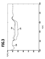
- FIG. 3 a diagram of the time dependence of an exit temperature is shown in the inventive method.
- the outlet temperature is the mixing temperature according to item 112 in FIG. 2 .
- the heating strands each have two solar collectors, each 100 m long.
- the outlet pressure is 110 bar, which is assumed to be constant. With a heating of 900 W / m 2 , a steam mass flow of 8.4 kg / s is assumed, which enters the system on the dew line. If no injection takes place, the mixing temperature is 430 ° C. An outlet temperature of 400 ° C requires (at steady state) the injection of 0.067 kg / s of water at a temperature of 275 ° C.
- the curve 114 shows the profile for the irradiated heating strands.
- the curve 116 shows the course for the shaded heating strands.
- the curve 118 shows the course of the resulting mixing temperature.
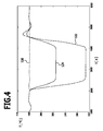
- FIG. 4 the result of a similar simulation is shown, wherein the first control circuit 96 is not present and a control takes place only via injection cooling.
- the curve 120 belongs to the irradiated heating strands and the curve 122 to the unirradiated heating strands.
- the mixing temperature has the course 124.
- a measurement of the individual mass flows is not required for the control method according to the invention. These are influenced by the mass flow control valves 92 without measurement.
- the first control circuit 96 has a supporting effect in order to obtain the most uniform temperature conditions at the outputs of the respective heating strands 66.
- a calculated mean value is used to regulate the mass flows.
- the mass flow control valves 82 cooperate expediently. For example, if a single heating string 66 is shaded, then there will be a large downward deviation from the average temperature value. This results in a strong throttling of the mass flow in this particular heating string 66. In the other heating strands 66, a slight increase in mass flow occurs through further opening of the respective mass flow control valves 82, because there is a deviation from the average temperature upwards. This gives a "mutual support" of the heating strands 66 in asymmetric disturbances of the irradiation conditions.
- the mass flow control valves 82 are started in a certain starting position in order to bring about a change in the mass flow distribution which is in opposite direction.
- the starting position is in particular a partial lift of a total lift.
- this partial stroke is 60% of the total stroke.
- control on the heating strands is carried out with slow feedback regulators which ensure that the feedback takes place in the direction of a predetermined value when a steady-state adjustment takes place.
- This predetermined value is, for example, an average setting of the corresponding mass flow control valve.
- the inventive concept can be used for solar thermal power plants with an evaporator section and an overheating section.
- the concept according to the invention may be implemented on a solar thermal power plant in which a gas (such as For example, air or helium) is heated.
- a gas such as For example, air or helium
- a plurality of parallel heating strands may be provided on a tower receiver, through which gaseous heat transfer medium flows.
- gaseous heat transfer medium flows.
- the individual mass flow control on the individual heating strands on the basis of a calculated mean value and control of mass flow control valves as a function of the difference between the measured temperatures and the mean value can also be carried out here.
Landscapes
- Engineering & Computer Science (AREA)
- Life Sciences & Earth Sciences (AREA)
- Sustainable Energy (AREA)
- Chemical & Material Sciences (AREA)
- Combustion & Propulsion (AREA)
- Sustainable Development (AREA)
- Mechanical Engineering (AREA)
- General Engineering & Computer Science (AREA)
- Physics & Mathematics (AREA)
- Thermal Sciences (AREA)
- Engine Equipment That Uses Special Cycles (AREA)
- Control Of Temperature (AREA)
Applications Claiming Priority (1)
| Application Number | Priority Date | Filing Date | Title |
|---|---|---|---|
| DE102007005562A DE102007005562A1 (de) | 2007-01-24 | 2007-01-24 | Verfahren zum Betreiben eines solarthermischen Kraftwerks und solarthermisches Kraftwerk |
Publications (2)
| Publication Number | Publication Date |
|---|---|
| EP1998109A2 true EP1998109A2 (fr) | 2008-12-03 |
| EP1998109A3 EP1998109A3 (fr) | 2014-04-02 |
Family
ID=39587274
Family Applications (1)
| Application Number | Title | Priority Date | Filing Date |
|---|---|---|---|
| EP08150509.1A Withdrawn EP1998109A3 (fr) | 2007-01-24 | 2008-01-22 | Procédé de fonctionnement d'une installation de chaleur industrielle thermique solaire et installation de chaleur industrielle thermique solaire |
Country Status (3)
| Country | Link |
|---|---|
| US (1) | US20080184789A1 (fr) |
| EP (1) | EP1998109A3 (fr) |
| DE (1) | DE102007005562A1 (fr) |
Cited By (1)
| Publication number | Priority date | Publication date | Assignee | Title |
|---|---|---|---|---|
| EP2053242A3 (fr) * | 2007-10-22 | 2014-10-22 | Deutsches Zentrum für Luft- und Raumfahrt e.V. | Procédé de fonctionnement d'une centrale thermique solaire et centrale thermique solaire |
Families Citing this family (23)
| Publication number | Priority date | Publication date | Assignee | Title |
|---|---|---|---|---|
| US8378280B2 (en) | 2007-06-06 | 2013-02-19 | Areva Solar, Inc. | Integrated solar energy receiver-storage unit |
| AU2008262309A1 (en) | 2007-06-06 | 2008-12-18 | Areva Solar, Inc. | Combined cycle power plant |
| US9022020B2 (en) | 2007-08-27 | 2015-05-05 | Areva Solar, Inc. | Linear Fresnel solar arrays and drives therefor |
| US20090056703A1 (en) | 2007-08-27 | 2009-03-05 | Ausra, Inc. | Linear fresnel solar arrays and components therefor |
| EP2430370A2 (fr) * | 2009-05-15 | 2012-03-21 | Areva Solar, Inc | Systèmes et procédés de production de vapeur à l'aide du rayonnement solaire |
| DE102009025455A1 (de) * | 2009-06-15 | 2011-01-05 | Deutsches Zentrum für Luft- und Raumfahrt e.V. | Verfahren zur Erzeugung von überhitztem Dampf an einem solarthermischen Kraftwerk und solarthermisches Kraftwerk |
| AU2010268769B2 (en) * | 2009-06-30 | 2017-01-12 | Sunrise Csp Pty Limited | Vapour only cycling of heat transfer fluid for the thermal storage of solar energy |
| AU2010313242A1 (en) | 2009-10-30 | 2012-05-24 | Areva Solar, Inc. | Dual fluid circuit system for generating a vaporous working fluid using solar energy |
| JP2013545064A (ja) * | 2010-09-30 | 2013-12-19 | ダウ グローバル テクノロジーズ エルエルシー | 集光型太陽熱発電プラントからの過熱スチームの製造方法 |
| JP5598288B2 (ja) * | 2010-11-30 | 2014-10-01 | Jfeエンジニアリング株式会社 | 太陽熱発電装置およびその運転方法 |
| DE102011004264A1 (de) * | 2011-02-17 | 2012-08-23 | Siemens Aktiengesellschaft | Solarthermischer Dampferzeuger |
| DE102011004267A1 (de) * | 2011-02-17 | 2012-08-23 | Siemens Aktiengesellschaft | Solarthermischer Dampferzeuger |
| WO2013002054A1 (fr) * | 2011-06-30 | 2013-01-03 | バブコック日立株式会社 | Chaudière à chaleur solaire et centrale électrique à chaleur solaire |
| JP5755098B2 (ja) * | 2011-10-04 | 2015-07-29 | 東京瓦斯株式会社 | 集熱システム |
| JP6038448B2 (ja) * | 2011-12-16 | 2016-12-07 | 三菱日立パワーシステムズ株式会社 | 太陽熱複合発電システム及び太陽熱複合発電方法 |
| DE102011056796B4 (de) * | 2011-12-21 | 2017-03-02 | Flagsol Gmbh | Solarthermisches Kraftwerk und Verfahren zur Regelung des Wärmeträgermediummassenstroms |
| US10393094B2 (en) | 2011-12-28 | 2019-08-27 | Sunrise Csp Pty Limited | Vapour only cycling of heat transfer fluid for the thermal storage of solar energy |
| DE102012206466A1 (de) * | 2012-04-19 | 2013-10-24 | Siemens Aktiengesellschaft | Verfahren und Vorrichtung zum Betrieb eines solarthermischen Kraftwerks |
| DE102012107353B4 (de) * | 2012-08-10 | 2015-05-07 | Deutsches Zentrum für Luft- und Raumfahrt e.V. | Solarthermisches Kraftwerk und Verfahren zum Betreiben eines solarthermischen Kraftwerks |
| US10020410B1 (en) * | 2012-11-01 | 2018-07-10 | University Of South Florida | Solar tiles and arrays |
| JP6315814B2 (ja) * | 2014-09-17 | 2018-04-25 | 株式会社神戸製鋼所 | エネルギー回収装置及び圧縮装置並びにエネルギー回収方法 |
| CN106403322B (zh) * | 2016-08-31 | 2018-05-15 | 徐荣吉 | 聚光式太阳能集热器及其集热液体的流程控制方法 |
| CN106322783B (zh) * | 2016-08-31 | 2019-01-29 | 徐荣吉 | 聚光式太阳能集热器及其集热液体的流程控制方法 |
Citations (2)
| Publication number | Priority date | Publication date | Assignee | Title |
|---|---|---|---|---|
| DE19623457A1 (de) | 1996-06-12 | 1997-12-18 | Siemens Ag | Verfahren zum Betreiben eines Solarkraftwerkes mit wenigstens einem solaren Dampferzeuger und Solarkraftwerk |
| DE10152971C1 (de) | 2001-10-19 | 2002-12-05 | Deutsch Zentr Luft & Raumfahrt | Solarthermisches Kraftwerk und Regelungsverfahren für ein solarthermisches Kraftwerk |
Family Cites Families (25)
| Publication number | Priority date | Publication date | Assignee | Title |
|---|---|---|---|---|
| US467398A (en) * | 1892-01-19 | Water-evaporator for steam-boilers | ||
| US4038970A (en) * | 1975-10-24 | 1977-08-02 | Ascoli John D | Solar water heater |
| US4289114A (en) * | 1978-09-12 | 1981-09-15 | The Babcock & Wilcox Company | Control system for a solar steam generator |
| US4296730A (en) * | 1978-09-12 | 1981-10-27 | The Babcock & Wilcox Company | Control system for a solar steam generator |
| US4284062A (en) * | 1978-10-30 | 1981-08-18 | Swindle Elro M | Solar collector system |
| IT1118685B (it) * | 1979-05-17 | 1986-03-03 | Francia Giovanni | Sistema di regolazione per una caldaia ad energia solare |
| FR2472745A1 (fr) * | 1979-12-28 | 1981-07-03 | Schlumberger Prospection | Dispositif |
| US4313419A (en) * | 1980-04-21 | 1982-02-02 | Halm Instrument Co., Inc. | Solar heating system |
| US4413614A (en) * | 1980-04-21 | 1983-11-08 | Halm Instrument Co., Inc. | Solar heating system |
| US4442720A (en) * | 1980-07-29 | 1984-04-17 | The United States Of America As Represented By The United States Department Of Energy | Sampling device for withdrawing a representative sample from single and multi-phase flows |
| US4384550A (en) * | 1980-12-19 | 1983-05-24 | Rockwell International Corporation | Thermal receiver |
| US4485803A (en) * | 1982-10-14 | 1984-12-04 | The Babcock & Wilcox Company | Solar receiver with interspersed panels |
| US4781173A (en) * | 1985-06-28 | 1988-11-01 | Juha Ven | Evaporating device and electric supply station provided with such an evaporating device |
| JPS6237645A (ja) * | 1985-06-28 | 1987-02-18 | ジユア ベン | 蒸発装置およびこのような蒸発装置を備えた発電ステ−シヨン |
| GB8817348D0 (en) * | 1988-07-21 | 1988-08-24 | Imperial College | Gas/liquid flow measurement |
| US5586027A (en) * | 1989-06-12 | 1996-12-17 | Western Atlas International, Inc. | Method and apparatus for determining flow rates in multi-phase fluid flow mixtures |
| DE4409197A1 (de) * | 1994-03-17 | 1995-09-21 | Siemens Ag | Verfahren und Einrichtung zur solaren Dampferzeugung |
| JP3022194B2 (ja) * | 1994-09-02 | 2000-03-15 | 三菱電機株式会社 | ダイバーシチ受信装置 |
| US5576495A (en) * | 1995-10-23 | 1996-11-19 | The Babcock & Wilcox Company | Two phase flow meter |
| US5705734A (en) * | 1996-07-17 | 1998-01-06 | Landis & Staefa, Inc. | Automated branch flow calibration in a HVAC distribution system |
| DE19724167C2 (de) * | 1997-06-07 | 1999-07-15 | Deutsch Zentr Luft & Raumfahrt | Verfahren und Vorrichtung zum Ermitteln eines Meßwerts einer Zielmeßgröße einer Mehr-Phasen-Strömung |
| BE1013693A3 (nl) * | 2000-09-19 | 2002-06-04 | Suria Holdings Sarl | Werkwijze en inrichting voor het vervaardigen van stoom met zonne-energie. |
| US7051529B2 (en) * | 2002-12-20 | 2006-05-30 | United Technologies Corporation | Solar dish concentrator with a molten salt receiver incorporating thermal energy storage |
| DE10329623B3 (de) * | 2003-06-25 | 2005-01-13 | Deutsches Zentrum für Luft- und Raumfahrt e.V. | Verfahren zur solarthermischen Gewinnung elektrischer Energie und solarthermisches Kraftwerk |
| AU2006327452B2 (en) * | 2006-06-16 | 2010-07-15 | Kawasaki Jukogyo Kabushiki Kaisha | Solar thermal electric power generation system, heating medium supply system, and temperature fluctuation suppressing device |
-
2007
- 2007-01-24 DE DE102007005562A patent/DE102007005562A1/de not_active Withdrawn
-
2008
- 2008-01-22 EP EP08150509.1A patent/EP1998109A3/fr not_active Withdrawn
- 2008-01-23 US US12/011,033 patent/US20080184789A1/en not_active Abandoned
Patent Citations (2)
| Publication number | Priority date | Publication date | Assignee | Title |
|---|---|---|---|---|
| DE19623457A1 (de) | 1996-06-12 | 1997-12-18 | Siemens Ag | Verfahren zum Betreiben eines Solarkraftwerkes mit wenigstens einem solaren Dampferzeuger und Solarkraftwerk |
| DE10152971C1 (de) | 2001-10-19 | 2002-12-05 | Deutsch Zentr Luft & Raumfahrt | Solarthermisches Kraftwerk und Regelungsverfahren für ein solarthermisches Kraftwerk |
Non-Patent Citations (1)
| Title |
|---|
| "Fortschrittsberichte VDI", 2005, VDI-VERLAG, article "Dynamische Systemsimulation und Auslegung des Abscheidesystems für die solare Direktverdampfung in Parabolrinnenkollektoren" |
Cited By (1)
| Publication number | Priority date | Publication date | Assignee | Title |
|---|---|---|---|---|
| EP2053242A3 (fr) * | 2007-10-22 | 2014-10-22 | Deutsches Zentrum für Luft- und Raumfahrt e.V. | Procédé de fonctionnement d'une centrale thermique solaire et centrale thermique solaire |
Also Published As
| Publication number | Publication date |
|---|---|
| EP1998109A3 (fr) | 2014-04-02 |
| DE102007005562A1 (de) | 2008-08-07 |
| US20080184789A1 (en) | 2008-08-07 |
Similar Documents
| Publication | Publication Date | Title |
|---|---|---|
| EP1998109A2 (fr) | Procédé de fonctionnement d'une installation de chaleur industrielle thermique solaire et installation de chaleur industrielle thermique solaire | |
| EP2454523B1 (fr) | Procédé de production de vapeur surchauffée dans une centrale héliothermique et centrale héliothermique | |
| EP2053242A2 (fr) | Procédé de fonctionnement d'une centrale thermique solaire et centrale thermique solaire | |
| EP0436536B1 (fr) | Procede et installation de generation de vapeur au moyen de chaleur perdue | |
| Valenzuela et al. | Control concepts for direct steam generation in parabolic troughs | |
| EP3014179A2 (fr) | Procédé de fonctionnement pour démarrer un générateur de vapeur à circulation forcée chauffé par héliothermie | |
| DE102007035976A1 (de) | Dampftemperatursteuerung unter Verwendung eines integrierten Funktionsblocks | |
| DE10144841C1 (de) | Solarthermisches Gas- und Dampfkraftwerk und Verfahren zur Umwandlung von thermischer Energie in elektrische Energie | |
| EP1766288B1 (fr) | Procede pour faire fonctionner un generateur de vapeur en continu | |
| DE102010040210A1 (de) | Verfahren zum Betreiben eines solarbeheizten Durchlaufdampferzeugers sowie solarthermischer Durchlaufdampferzeuger | |
| EP2673562A2 (fr) | Procédé permettant de faire fonctionner un générateur de vapeur à chauffage direct pour une centrale solaire thermique | |
| DE102012103457B4 (de) | Verfahren zum Betreiben eines solarthermischen Kraftwerkes | |
| DE10152971C1 (de) | Solarthermisches Kraftwerk und Regelungsverfahren für ein solarthermisches Kraftwerk | |
| DE4447591C2 (de) | Solaranlage zur Erzeugung von Dampf mittels konzentrierter Sonnenstrahlung | |
| DE2503411A1 (de) | Heisswassererzeuger und verfahren zur schockpruefung von rohrleitungs- fertigteilen unter verwendung eines heisswassererzeugers | |
| WO2012110330A2 (fr) | Procédé pour faire fonctionner un générateur de vapeur à récupération de chaleur héliothermique | |
| WO2013120740A2 (fr) | Centrale héliothermique et procédé pour faire fonctionner une centrale héliothermique | |
| EP2638251B1 (fr) | Procédé pour faire fonctionner une centrale à collecteurs cylindro-paraboliques héliothermique | |
| DE10311223A1 (de) | Verfahren und Vorrichtung zur Prozessregelung oder -steuerung von thermischen Lastwechseln von einem von einem Medium durchströmten krümmungsbehinderten und/oder dickwandigen Bauteil in einem thermischen System | |
| CH642155A5 (de) | Dampferzeuger mit zwischenwand zwischen zwei brennkammern. | |
| DE102013221889B4 (de) | Receiver für Solarenergiegewinnungsanlagen | |
| EP2825736B1 (fr) | Procédé et dispositif pour faire fonctionner une centrale héliothermique | |
| WO2011051118A1 (fr) | Procédé et système de commande permettant de faire fonctionner une centrale thermique solaire et centrale thermique solaire | |
| DE3407129C2 (fr) | ||
| WO2018036872A1 (fr) | Procédé de commande et/ou de régulation d'une centrale solaire thermique et centrale solaire thermique |
Legal Events
| Date | Code | Title | Description |
|---|---|---|---|
| PUAI | Public reference made under article 153(3) epc to a published international application that has entered the european phase |
Free format text: ORIGINAL CODE: 0009012 |
|
| AK | Designated contracting states |
Kind code of ref document: A2 Designated state(s): AT BE BG CH CY CZ DE DK EE ES FI FR GB GR HR HU IE IS IT LI LT LU LV MC MT NL NO PL PT RO SE SI SK TR |
|
| AX | Request for extension of the european patent |
Extension state: AL BA MK RS |
|
| PUAL | Search report despatched |
Free format text: ORIGINAL CODE: 0009013 |
|
| AK | Designated contracting states |
Kind code of ref document: A3 Designated state(s): AT BE BG CH CY CZ DE DK EE ES FI FR GB GR HR HU IE IS IT LI LT LU LV MC MT NL NO PL PT RO SE SI SK TR |
|
| AX | Request for extension of the european patent |
Extension state: AL BA MK RS |
|
| RIC1 | Information provided on ipc code assigned before grant |
Ipc: F22B 35/16 20060101ALI20140227BHEP Ipc: F24J 2/40 20060101ALI20140227BHEP Ipc: F03G 6/06 20060101ALI20140227BHEP Ipc: F22B 1/00 20060101AFI20140227BHEP |
|
| AKY | No designation fees paid | ||
| AXX | Extension fees paid |
Extension state: MK Extension state: RS Extension state: AL Extension state: BA |
|
| REG | Reference to a national code |
Ref country code: DE Ref legal event code: R108 |
|
| REG | Reference to a national code |
Ref country code: DE Ref legal event code: R108 Effective date: 20141210 |
|
| STAA | Information on the status of an ep patent application or granted ep patent |
Free format text: STATUS: THE APPLICATION IS DEEMED TO BE WITHDRAWN |
|
| 18D | Application deemed to be withdrawn |
Effective date: 20141003 |