EP2455265B1 - Actionneur de frein de stationnement - Google Patents
Actionneur de frein de stationnement Download PDFInfo
- Publication number
- EP2455265B1 EP2455265B1 EP11187780.9A EP11187780A EP2455265B1 EP 2455265 B1 EP2455265 B1 EP 2455265B1 EP 11187780 A EP11187780 A EP 11187780A EP 2455265 B1 EP2455265 B1 EP 2455265B1
- Authority
- EP
- European Patent Office
- Prior art keywords
- stop
- cable
- sleeve
- screw
- parking brake
- Prior art date
- Legal status (The legal status is an assumption and is not a legal conclusion. Google has not performed a legal analysis and makes no representation as to the accuracy of the status listed.)
- Not-in-force
Links
Images


Classifications
-
- B—PERFORMING OPERATIONS; TRANSPORTING
- B60—VEHICLES IN GENERAL
- B60T—VEHICLE BRAKE CONTROL SYSTEMS OR PARTS THEREOF; BRAKE CONTROL SYSTEMS OR PARTS THEREOF, IN GENERAL; ARRANGEMENT OF BRAKING ELEMENTS ON VEHICLES IN GENERAL; PORTABLE DEVICES FOR PREVENTING UNWANTED MOVEMENT OF VEHICLES; VEHICLE MODIFICATIONS TO FACILITATE COOLING OF BRAKES
- B60T7/00—Brake-action initiating means
- B60T7/02—Brake-action initiating means for personal initiation
- B60T7/08—Brake-action initiating means for personal initiation hand actuated
- B60T7/10—Disposition of hand control
- B60T7/107—Disposition of hand control with electrical power assistance
-
- B—PERFORMING OPERATIONS; TRANSPORTING
- B60—VEHICLES IN GENERAL
- B60T—VEHICLE BRAKE CONTROL SYSTEMS OR PARTS THEREOF; BRAKE CONTROL SYSTEMS OR PARTS THEREOF, IN GENERAL; ARRANGEMENT OF BRAKING ELEMENTS ON VEHICLES IN GENERAL; PORTABLE DEVICES FOR PREVENTING UNWANTED MOVEMENT OF VEHICLES; VEHICLE MODIFICATIONS TO FACILITATE COOLING OF BRAKES
- B60T11/00—Transmitting braking action from initiating means to ultimate brake actuator without power assistance or drive or where such assistance or drive is irrelevant
- B60T11/04—Transmitting braking action from initiating means to ultimate brake actuator without power assistance or drive or where such assistance or drive is irrelevant transmitting mechanically
- B60T11/046—Using cables
-
- B—PERFORMING OPERATIONS; TRANSPORTING
- B60—VEHICLES IN GENERAL
- B60T—VEHICLE BRAKE CONTROL SYSTEMS OR PARTS THEREOF; BRAKE CONTROL SYSTEMS OR PARTS THEREOF, IN GENERAL; ARRANGEMENT OF BRAKING ELEMENTS ON VEHICLES IN GENERAL; PORTABLE DEVICES FOR PREVENTING UNWANTED MOVEMENT OF VEHICLES; VEHICLE MODIFICATIONS TO FACILITATE COOLING OF BRAKES
- B60T13/00—Transmitting braking action from initiating means to ultimate brake actuator with power assistance or drive; Brake systems incorporating such transmitting means, e.g. air-pressure brake systems
- B60T13/74—Transmitting braking action from initiating means to ultimate brake actuator with power assistance or drive; Brake systems incorporating such transmitting means, e.g. air-pressure brake systems with electrical assistance or drive
- B60T13/746—Transmitting braking action from initiating means to ultimate brake actuator with power assistance or drive; Brake systems incorporating such transmitting means, e.g. air-pressure brake systems with electrical assistance or drive and mechanical transmission of the braking action
-
- B—PERFORMING OPERATIONS; TRANSPORTING
- B60—VEHICLES IN GENERAL
- B60T—VEHICLE BRAKE CONTROL SYSTEMS OR PARTS THEREOF; BRAKE CONTROL SYSTEMS OR PARTS THEREOF, IN GENERAL; ARRANGEMENT OF BRAKING ELEMENTS ON VEHICLES IN GENERAL; PORTABLE DEVICES FOR PREVENTING UNWANTED MOVEMENT OF VEHICLES; VEHICLE MODIFICATIONS TO FACILITATE COOLING OF BRAKES
- B60T7/00—Brake-action initiating means
- B60T7/02—Brake-action initiating means for personal initiation
- B60T7/04—Brake-action initiating means for personal initiation foot actuated
- B60T7/042—Brake-action initiating means for personal initiation foot actuated by electrical means, e.g. using travel or force sensors
-
- B—PERFORMING OPERATIONS; TRANSPORTING
- B60—VEHICLES IN GENERAL
- B60T—VEHICLE BRAKE CONTROL SYSTEMS OR PARTS THEREOF; BRAKE CONTROL SYSTEMS OR PARTS THEREOF, IN GENERAL; ARRANGEMENT OF BRAKING ELEMENTS ON VEHICLES IN GENERAL; PORTABLE DEVICES FOR PREVENTING UNWANTED MOVEMENT OF VEHICLES; VEHICLE MODIFICATIONS TO FACILITATE COOLING OF BRAKES
- B60T7/00—Brake-action initiating means
- B60T7/02—Brake-action initiating means for personal initiation
- B60T7/08—Brake-action initiating means for personal initiation hand actuated
- B60T7/085—Brake-action initiating means for personal initiation hand actuated by electrical means, e.g. travel, force sensors
-
- F—MECHANICAL ENGINEERING; LIGHTING; HEATING; WEAPONS; BLASTING
- F16—ENGINEERING ELEMENTS AND UNITS; GENERAL MEASURES FOR PRODUCING AND MAINTAINING EFFECTIVE FUNCTIONING OF MACHINES OR INSTALLATIONS; THERMAL INSULATION IN GENERAL
- F16C—SHAFTS; FLEXIBLE SHAFTS; ELEMENTS OR CRANKSHAFT MECHANISMS; ROTARY BODIES OTHER THAN GEARING ELEMENTS; BEARINGS
- F16C1/00—Flexible shafts; Mechanical means for transmitting movement in a flexible sheathing
- F16C1/10—Means for transmitting linear movement in a flexible sheathing, e.g. "Bowden-mechanisms"
- F16C1/12—Arrangements for transmitting movement to or from the flexible member
- F16C1/14—Construction of the end-piece of the flexible member; Attachment thereof to the flexible member
-
- F—MECHANICAL ENGINEERING; LIGHTING; HEATING; WEAPONS; BLASTING
- F16—ENGINEERING ELEMENTS AND UNITS; GENERAL MEASURES FOR PRODUCING AND MAINTAINING EFFECTIVE FUNCTIONING OF MACHINES OR INSTALLATIONS; THERMAL INSULATION IN GENERAL
- F16C—SHAFTS; FLEXIBLE SHAFTS; ELEMENTS OR CRANKSHAFT MECHANISMS; ROTARY BODIES OTHER THAN GEARING ELEMENTS; BEARINGS
- F16C1/00—Flexible shafts; Mechanical means for transmitting movement in a flexible sheathing
- F16C1/10—Means for transmitting linear movement in a flexible sheathing, e.g. "Bowden-mechanisms"
- F16C1/12—Arrangements for transmitting movement to or from the flexible member
- F16C1/16—Arrangements for transmitting movement to or from the flexible member in which the end-piece is guided rectilinearly
-
- F—MECHANICAL ENGINEERING; LIGHTING; HEATING; WEAPONS; BLASTING
- F16—ENGINEERING ELEMENTS AND UNITS; GENERAL MEASURES FOR PRODUCING AND MAINTAINING EFFECTIVE FUNCTIONING OF MACHINES OR INSTALLATIONS; THERMAL INSULATION IN GENERAL
- F16C—SHAFTS; FLEXIBLE SHAFTS; ELEMENTS OR CRANKSHAFT MECHANISMS; ROTARY BODIES OTHER THAN GEARING ELEMENTS; BEARINGS
- F16C2361/00—Apparatus or articles in engineering in general
- F16C2361/45—Brakes
-
- F—MECHANICAL ENGINEERING; LIGHTING; HEATING; WEAPONS; BLASTING
- F16—ENGINEERING ELEMENTS AND UNITS; GENERAL MEASURES FOR PRODUCING AND MAINTAINING EFFECTIVE FUNCTIONING OF MACHINES OR INSTALLATIONS; THERMAL INSULATION IN GENERAL
- F16D—COUPLINGS FOR TRANSMITTING ROTATION; CLUTCHES; BRAKES
- F16D2121/00—Type of actuator operation force
- F16D2121/18—Electric or magnetic
- F16D2121/24—Electric or magnetic using motors
Definitions
- the present invention relates to a parking brake actuator consisting of a housing housing an electric motor driving via a screw transmission formed of a fixed nut in position and free in rotation controlling a screw locked in rotation and free in translation, this screw having an end connected to the cable of the handbrake, housed in a barrel whose output carries a tip with a stop retaining the sheath of the brake cable.
- the invention also relates to a parking brake system equipped with such a brake actuator.
- the head of the screw which carries the cable stop is housed in a barrel whose front end is provided with a stop receiving and retaining the sheath of the Bowden cable connected to the wheel brakes.
- the Bowden cable is aligned with the axis of the barrel which is also that of the screw so that the device operates normally without any effort other than a pulling force being exerted on the cable and the screw.
- the cable is aligned with the axis of the screw of the actuator so that the free portion of the cable inside the barrel is itself in the axis and n induces no radial or transverse force on the screw head and, consequently, on the screw.
- This is then subjected by the nut which causes the translation of the screw only tensile forces so that the operation of the actuator remains silent even in extreme implantation conditions of the actuator with a bowden cable of heavily curved parking brake.
- This means according to the invention makes it possible, if necessary, to transform the brake actuator according to the vehicle in which it is implanted, that is to say the importance of the space available for fitting the parking brake between the brake actuator. actuator and wheels to brake.
- the barrel comprises externally a thread and the endpiece is formed of a large diameter screwing sleeve, intended to cap the end of the barrel and an outer sleeve of reduced diameter forming with the previous, a shoulder resting against the stop and the sleeve stiffener consists of a front part covering a portion of the Bowden cable at the front of the stop sleeve, an intermediate portion overlapping the sleeve and the outer sleeve of the bit and forming a stop with the rear portion which covers the sleeve screwing.
- the rear portion of the stiffening sleeve ends with a bead so as to clap behind the rear edge of the screwing sleeve.
- This embodiment of the stiffening sleeve allows easy placement. It is the same with his removal if necessary.
- the stiffening sleeve is a piece of plastic material.
- the stiffening sleeve advantageously comprises a longitudinal slot.
- a handbrake actuator 100 consists of a housing 110 equipped with an electric motor driven by a gearbox, a screw transmission formed of a fixed nut in translation, receiving a screw 120, movable in translation but blocked in rotation.
- This screw 120 moves in the housing 111c of axis xx of the barrel 111 of the housing to actuate the parking brakes via a Bowden cable 140 connected to the parking brakes.
- the cable 140 is composed of an inner cable 141 and a sheath 142.
- the screw 120 ends with a nut-shaped head 121 which fixes the end 141a. 141.
- the screw 120 is moved in one direction or the other in translation along its axis xx to pull or release the inner cable 141 and set the parking brake or release.
- the meshing between the nut and the screw 120 is monodirectional, that is to say that only the nut can cause the translation of the screw. The opposite is not possible: a tensile force exerted on the screw 120 does not drive the nut so that the screw 120 is blocked as soon as the rotation of the nut stops.
- the motor and transmission are not shown in the drawings.
- the end 111a of the barrel 111 carries a stop 130 in which is placed the sheath 142 of the cable 140 to be retained.
- the Figure 1B shows the partial installation of this actuator 100 handbrake with the cable 140 and end 140A very curved because of the available space, very limited in the vehicle.
- the bending of the end 140A results in a bending of the inner cable 141 which is reflected on the cable portion 141A beyond the sheath, between the stop 130 and the head 121 of the screw 120.
- the bending of the end 140 exerts efforts on the abutment 130 then functioning as a kind of ball joint transmitting the deformation of the inner cable 141, from the outside towards the inside of the barrel 111.
- This deformation is represented exaggerated at the Figure 1B to highlight it for its description.
- the deformation of the inner cable on its part 141a is small but it is sufficient to create troublesome effects.
- This bending exerts on the screw head 121, a radial force that must be compensated.
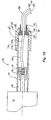
- the figure 2 shows an embodiment of a parking brake actuator 100 provided with a stiffening sleeve 150 according to the invention.
- This figure is limited to the representation of the front end 111a of the barrel bearing as it appears in FIG. Figure 1A , the stop 130 and its end 135.
- the stiffening sleeve 150 overlaps the stop 130 and the end piece 135 by maintaining a length of the Bowden cable 140 at the outlet of the sleeve 131 of the abutment 130.
- the stiffening sleeve 150 consists of a tubular front portion 151 of inner diameter adapted to the outer diameter of the Bowden cable 140 so as to marry it to the front of the sleeve 131 against which the outer portion 151 is supported.
- the stiffening sleeve 150 is trimmed according to the installation requirements of the parking brake actuator, on the stop and the tip by sliding over the Bowden cable and hooking by clipping behind the tip 135 .
- the figure 3 shows another embodiment of a stiffening sleeve 250 having as the previous an outer portion 251 followed by an intermediate portion 252 and a rear portion 253, the latter being provided with a bead 254.
- This sleeve is provided with a longitudinal slot 255 to facilitate its adaptation to different abutment geometries 130 and tip 135.
- the invention applies generally to parking brake systems of motor vehicles.
Landscapes
- Engineering & Computer Science (AREA)
- Mechanical Engineering (AREA)
- Transportation (AREA)
- General Engineering & Computer Science (AREA)
- Health & Medical Sciences (AREA)
- Oral & Maxillofacial Surgery (AREA)
- Braking Arrangements (AREA)
- Braking Systems And Boosters (AREA)
- Transmission Of Braking Force In Braking Systems (AREA)
Description
- La présente invention concerne un actionneur de frein de stationnement composé d'un boîtier logeant un moteur électrique entraînant par l'intermédiaire d'une transmission à vis formée d'un écrou fixe en position et libre en rotation commandant une vis bloquée en rotation et libre en translation, cette vis ayant une extrémité reliée au câble du frein à main, logée dans un canon dont la sortie porte un embout avec une butée retenant la gaine du câble de frein.
- L'invention concerne également un système de frein de stationnement équipé d'un tel actionneur de frein.
-
FR 2 928 185 EP 1 255 061 ,WO 2006/050770 ,US 2 899 836 ,US 4 696 203 ,WO 2004/013501 ,GB 2 151 758 US 6 053 064 décrivent la mise en oeuvre des câbles d'actionnement. - Les actionneurs de frein de stationnement ou freins à main remplaçant le levier de frein à main pour serrer le frein à main ou le libérer, sont commandés à partir d'un bouton qui déclenche la manoeuvre de serrage ou de libération du frein.
- Un actionneur de frein de stationnement est constitué par un boîtier logeant un moteur électrique entraînant par des pignons, un écrou fixe en translation, qui déplace une tige filetée à laquelle est relié un arrêt du câble passant dans une gaine et relié au frein de stationnement (câble Bowden).
- La tête de la vis qui porte l'arrêt de câble est logée dans un canon dont l'extrémité avant est munie d'une butée recevant et retenant la gaine du câble Bowden relié aux freins des roues.
- Dans les conditions d'installation normales, le câble Bowden est aligné sur l'axe du canon qui est aussi celui de la vis de sorte que le dispositif fonctionne normalement sans qu'un effort autre qu'un effort de traction ne soit exercé sur le câble et la vis.
- Toutefois, pour monter un tel frein à main électrique dans un encombrement très réduit, il faut, dans certaines conditions, cintrer fortement le câble Bowden, en particulier, à la sortie du canon de l'actionneur. Ce cintrage entraîne également un cintrage du câble proprement dit qui se répercute dans la partie libre du câble à l'intérieur du canon engendrant un effort radial appliqué à la vis. Cet effort radial se traduit par un bruit de broutage très fort du fait des efforts et des réactions exercés au niveau de l'écrou entraînant la vis.
- Ce bruit qui serait perçu de manière très gênante à l'intérieur et à l'extérieur du véhicule, rendant impossible l'application d'un tel système de frein à un véhicule de tourisme sans place suffisante pour le câble de frein.
- La présente invention a pour but de développer un moyen permettant d'adapter un actionneur de frein de stationnement dans un encombrement disponible très réduit, évitant les bruits de fonctionnement du frein de stationnement quelles que soient les conditions d'implantation de l'actionneur dans le véhicule et sans nécessiter de transformations importantes et coûteuses du système de frein de stationnement.
- A cet effet, l'invention concerne un actionneur de frein de stationnement du type défini ci-dessus caractérisé en ce qu'il comporte un manchon raidisseur emmanché sur l'extrémité du canon autour de la butée et de l'embout formant l'arrêt de la gaine du câble de frein pour bloquer l'embout et la butée et éviter la déformation de l'extrémité du câble de frein au-delà de la butée, de manière à aligner le câble intérieur sur l'axe xx de la vis à l'intérieur du canon et éviter tout effort transversal sur la vis et l'écrou qui l'entraîne.
- Grâce à l'invention, en sortie d'actionneur le câble est aligné sur l'axe de la vis de l'actionneur de sorte que la partie libre du câble à l'intérieur du canon est elle-même dans l'axe et n'induit aucun effort radial ou transversal sur la tête de vis et, par suite, sur la vis. Celle-ci n'est alors soumise par l'écrou qui entraîne la translation de la vis qu'à des efforts de traction de sorte que le fonctionnement de l'actionneur reste silencieux même dans des conditions d'implantation extrêmes de l'actionneur avec un câble Bowden de frein de stationnement fortement cintré.
- Ce moyen selon l'invention permet de transformer si nécessaire l'actionneur de frein en fonction du véhicule dans lequel il est implanté c'est-à-dire de l'importance de la place disponible pour le montage du frein à main entre l'actionneur et les roues à freiner.
- Suivant une autre caractéristique avantageuse de l'invention, le canon comporte extérieurement un filetage et l'embout est formé d'un manchon de vissage de grand diamètre, destiné à coiffer l'extrémité du canon et un manchon extérieur de diamètre réduit formant avec le précédent, un épaulement s'appuyant contre la butée et le manchon raidisseur se compose d'une partie avant coiffant une partie du câble Bowden à l'avant du manchon de la butée, une partie intermédiaire chevauchant le manchon et le manchon extérieur de l'embout et formant une butée avec la partie arrière qui coiffe le manchon de vissage.
- Suivant une autre caractéristique avantageuse, la partie arrière du manchon raidisseur se termine par un bourrelet de manière à se clipser derrière le bord arrière du manchon de vissage.
- Cette forme de réalisation du manchon raidisseur permet une mise en place facile. Il en est de même de son enlèvement si nécessaire.
- Suivant une autre caractéristique avantageuse le manchon raidisseur est une pièce en matière plastique. Pour s'adapter à différentes formes et sections de butée et d'embout, le manchon raidisseur comporte avantageusement une fente longitudinale.
- La présente invention sera décrite ci-après de manière plus détaillée à l'aide d'un exemple de réalisation de l'invention comparé à l'état de la technique :
- la
figure 1A montre un actionneur de frein de stationnement connu installé dans des conditions d'encombrement normales, - la
figure 1B montre l'actionneur de frein de lafigure 1A installé dans des conditions d'encombrement extrêmement réduites, - la
figure 2 montre l'actionneur de frein de stationnement selon l'invention, installé également dans des conditions d'encombrement extrêmement réduit, - la
figure 3 est une vue en coupe agrandie d'un exemple de manchon raidisseur pour l'extrémité du canon au niveau de la fixation de la gaine du câble. - Selon les
figures 1A ,1B , un actionneur de frein à main 100, se compose d'un boîtier 110 équipé d'un moteur électrique entraînant par un réducteur, une transmission à vis formée d'un écrou fixe en translation, recevant une vis 120, mobile en translation mais bloquée en rotation. Cette vis 120 se déplace dans le logement 111c d'axe xx du canon 111 du boîtier pour actionner les freins de stationnement par l'intermédiaire d'un câble Bowden 140 relié aux freins de stationnement. Le câble 140 est composé d'un câble intérieur 141 et d'une gaine 142. La vis 120 se termine par une tête 121 en forme d'écrou-chapeau qui fixe l'extrémité 141a du câble intérieur 141. La vis 120 est déplacée dans un sens ou dans l'autre en translation suivant son axe xx pour tirer ou relâcher le câble intérieur 141 et serrer le frein à main ou le libérer. L'engrènement entre l'écrou et la vis 120 est monodirectionnel, c'est-à-dire que seul l'écrou peut provoquer la translation de la vis. L'inverse n'est pas possible : un effort de traction exercé sur la vis 120 ne permet pas d'entraîner l'écrou de sorte que la vis 120 est bloquée dès que la rotation de l'écrou s'arrête. Le moteur et la transmission ne sont pas représentés dans les dessins. - L'extrémité 111a du canon 111 porte une butée 130 dans laquelle se place la gaine 142 du câble 140 pour être retenue.
- La butée 130 se compose d'un manchon 131 recevant la gaine et traversé par le câble intérieur 141. Ce manchon 131 prolonge le corps 132 servant d'appui contre l'extrémité 111c du canon 111. Le corps 132 est lui-même bordé par une gorge 133 de façon à s'engager en partie dans l'ouverture du canon tout en s'appuyant contre celle-ci dans le sens d'une traction exercée sur le câble (vers la gauche sur la
figure 1A ). - La butée 130 est coiffée par un embout 135 formé d'un manchon extérieur 136 rejoignant un manchon de vissage 138 par l'intermédiaire d'une partie formant un épaulement 137. Le manchon extérieur 136 coiffe le manchon 131 et le manchon de vissage 138 chevauche l'extrémité du canon pour s'accrocher par vissage au filetage 111b en retrait de l'extrémité 111a du canon. La butée 130 est ainsi retenue fermement contre l'extrémité du canon. Le logement 111c à l'intérieur du canon 111 est libre et permet la circulation de la vis 120 et de sa tête 121.
- A la
figure 1A l'actionneur de frein 100 est installé dans des conditions d'encombrement normales de sorte que le câble Bowden 140 en sortie du canon 111 de l'actionneur reste aligné ou sensiblement aligné sur l'axe xx et n'induit pas de déformation dans la partie 141A du câble intérieur 141 dans le logement 111c du canon 111. - La
figure 1B montre l'installation partielle de cet actionneur 100 de frein à main avec le câble 140 et son extrémité 140A très cintrée à cause de la place disponible, très limitée dans le véhicule. - Le cintrage de l'extrémité 140A se traduit par un cintrage du câble intérieur 141 qui se répercute sur la partie de câble 141A au-delà de la gaine, entre la butée 130 et la tête 121 de la vis 120. Le cintrage de l'extrémité 140 exerce des efforts sur la butée 130 fonctionnant alors comme une sorte de rotule transmettant la déformation du câble intérieur 141, de l'extérieur vers l'intérieur du canon 111. Cette déformation est représentée exagérée à la
figure 1B pour la mettre en évidence en vue de sa description. En réalité la déformation du câble intérieur sur sa partie 141a est faible mais elle est suffisante pour créer des effets gênants. Ce cintrage exerce sur la tête de vis 121, un effort radial qu'il faut compenser. Cet effort radial pour lequel le système vis-écrou n'est pas conçu se traduit par un bruit de broutage très important lorsque l'écrou tourne sur la vis 120 que cela soit dans le sens du serrage du frein ou de sa libération puisque, dans les deux cas, le câble de frein reste cintré à l'intérieur du canon. - La
figure 2 montre un mode de réalisation d'un actionneur de frein de stationnement 100 muni d'un manchon raidisseur 150 selon l'invention. Cette figure se limite à la représentation de l'extrémité avant 111a du canon portant comme cela apparaît à lafigure 1A , la butée 130 et son embout 135. Le manchon raidisseur 150 chevauche la butée 130 et l'embout 135 en maintenant une longueur du câble Bowden 140 à la sortie du manchon 131 de la butée 130. Le manchon raidisseur 150 se compose d'une partie avant 151 tubulaire, de diamètre intérieur adapté au diamètre extérieur du câble Bowden 140 de manière à épouser celui-ci à l'avant du manchon 131 contre lequel la partie extérieure 151 vient s'appuyer. - La partie intermédiaire 152 coiffe à la fois le manchon 131 de la butée 130 et le manchon extérieur 136 de l'embout 135 en formant un épaulement venant contre le manchon extérieur 136. Le raidisseur 150 se poursuit côté arrière, c'est-à-dire le côté tourné vers l'actionneur, par une partie arrière 153, cylindrique couvrant toute la longueur de l'embout 135 pour s'accrocher derrière celui-ci par un léger bourrelet élastique 154.
- Le manchon raidisseur 150 s'emmanche selon les nécessités d'installation de l'actionneur de frein de stationnement, sur la butée et l'embout en le glissant par-dessus le câble Bowden et en l'accrochant par clippage derrière l'embout 135.
- La partie avant 151 du manchon raidisseur 150 permet de tenir fermement le câble Bowden 140 sur une certaine partie de sa longueur pour éviter que la partie de câble intérieur 141A dans le logement 111c ne soit déviée de la ligne d'axe xx et n'engendre les nuisances évoquées ci-dessus. Lorsque le manchon raidisseur 150 n'est pas nécessaire, celui-ci peut être enlevé. Néanmoins, comme il renforce le guidage du câble Bodwen en sortie de canon d'actionneur, il est préférable de le laisser en place si les conditions d'installation de l'actionneur le permettent.
- La
figure 3 montre un autre mode de réalisation d'un manchon raidisseur 250 comportant comme le précédent une partie extérieure 251 suivie d'une partie intermédiaire 252 et d'une partie arrière 253, cette dernière étant munie d'un bourrelet 254. Ce manchon est muni d'une fente longitudinale 255 pour faciliter son adaptation à différentes géométries de butée 130 et d'embout 135. - L'invention s'applique de manière générale aux systèmes de frein de stationnement de véhicules automobiles.
-
100 Actionneur de frein de stationnement 110 Boîtier 111 Canon 111a Extrémité du canon 111b Filetage extérieur 111c Logement du canon 120 Vis 121 Tête de vis 130 Butée 131 Manchon 132 Corps (appui contre le canon) 133 Gorge 135 Embout 136 Manchon extérieur 137 Epaulement 138 Manchon de vissage 140 Câble Bowden 140A Extrémité cintrée du câble 140 141 Câble intérieur 141a Extrémité du câble intérieur 141A Extrémité cintrée du câble intérieur 141 142 Gaine 150 Manchon raidisseur 151 Partie extérieure 152 Partie intermédiaire 153 Partie arrière 154 Bourrelet 250 Manchon raidisseur 251 Partie extérieure 252 Partie intermédiaire 253 Partie arrière 254 Bourrelet 255 Fente longitudinale
Claims (5)
- Actionneur de frein de stationnement composé d'un boîtier (110) logeant un moteur électrique entraînant par l'intermédiaire d'une transmission à vis formée d'un écrou fixe en position et libre en rotation commandant une vis (120) bloquée en rotation et libre en translation, cette vis (120) ayant une extrémité (121) reliée au câble (140) du frein à main, logée dans un canon (111) dont la sortie porte un embout (135) avec une butée (130) retenant la gaine (142) du câble de frein (140),
caractérisé en ce qu'
il comporte un manchon raidisseur (150) emmanché sur l'extrémité (111a) du canon (111) autour de la butée (130) et de l'embout (135) formant l'arrêt de la gaine (142) du câble de frein (140) pour bloquer l'embout (135) et la butée (130) et éviter la déformation de l'extrémité du câble de frein au-delà de la butée, de manière à aligner le câble intérieur (141) sur l'axe (xx) de la vis (120) à l'intérieur du canon (111) et éviter tout effort transversal sur la vis (120) et l'écrou qui l'entraîne. - Actionneur selon la revendication 1,
caractérisé en ce que
le canon (111) comporte extérieurement un filetage (111b) et l'embout (135) est formé d'un manchon de vissage (138) de grand diamètre, destiné à coiffer l'extrémité (11 la) du canon (111) et un manchon extérieur (136) de diamètre réduit formant avec le précédent, un épaulement (137) s'appuyant contre la butée (130) et le manchon raidisseur (150) se compose d'une partie avant (151) coiffant une partie du câble Bowden (140) à l'avant du manchon (131) de la butée (130), une partie intermédiaire (152) chevauchant le manchon (131) et le manchon extérieur (136) de l'embout (135) et formant une butée (154) avec la partie arrière (153) qui coiffe le manchon de vissage (138). - Actionneur selon la revendication 2,
caractérisé en ce que
la partie arrière (153) du manchon raidisseur (150) se termine par un bourrelet (154) de manière à se clipser derrière le bord arrière du manchon de vissage (138). - Actionneur selon la revendication 1,
caractérisé en ce que
le manchon raidisseur (150) est une pièce en matière plastique. - Système de frein de stationnement commandé par un câble et muni d'un actionneur de frein de stationnement selon l'une quelconque des revendications 1 à 4.
Priority Applications (1)
| Application Number | Priority Date | Filing Date | Title |
|---|---|---|---|
| PL11187780T PL2455265T3 (pl) | 2010-11-19 | 2011-11-04 | Mechanizm wykonawczy hamulca postojowego |
Applications Claiming Priority (1)
| Application Number | Priority Date | Filing Date | Title |
|---|---|---|---|
| FR1004524A FR2967632B1 (fr) | 2010-11-19 | 2010-11-19 | Actionneur de frein de stationnement |
Publications (2)
| Publication Number | Publication Date |
|---|---|
| EP2455265A1 EP2455265A1 (fr) | 2012-05-23 |
| EP2455265B1 true EP2455265B1 (fr) | 2013-07-24 |
Family
ID=44126880
Family Applications (1)
| Application Number | Title | Priority Date | Filing Date |
|---|---|---|---|
| EP11187780.9A Not-in-force EP2455265B1 (fr) | 2010-11-19 | 2011-11-04 | Actionneur de frein de stationnement |
Country Status (5)
| Country | Link |
|---|---|
| EP (1) | EP2455265B1 (fr) |
| ES (1) | ES2431517T3 (fr) |
| FR (1) | FR2967632B1 (fr) |
| PL (1) | PL2455265T3 (fr) |
| PT (1) | PT2455265E (fr) |
Family Cites Families (8)
| Publication number | Priority date | Publication date | Assignee | Title |
|---|---|---|---|---|
| US2899836A (en) * | 1955-02-16 | 1959-08-18 | Pacific Scient Aeroproducts | Push-pull cable apparatus |
| US4537090A (en) * | 1983-12-19 | 1985-08-27 | Eaton Corporation | Vernier control device |
| US4696203A (en) * | 1984-09-10 | 1987-09-29 | Arens Controls, Inc. | Push-pull vernier control and method of manufacture thereof |
| US6053064A (en) * | 1998-05-01 | 2000-04-25 | L & P Property Management Company | Lumbar support screw actuator |
| GB0110457D0 (en) * | 2001-04-28 | 2001-06-20 | Meritor Light Vehicle Sys Ltd | Cable linkage |
| DE10234813A1 (de) * | 2002-07-31 | 2004-02-19 | Schwarzbich, Jörg | Spannschloss für Kabelzug |
| DE102004054864A1 (de) * | 2004-11-12 | 2006-05-24 | Ims Gear Gmbh | Spindel |
| FR2928185B1 (fr) * | 2008-02-28 | 2010-06-11 | Peugeot Citroen Automobiles Sa | Embout de liaison pour cable d'actionnement coulissant dans une gaine |
-
2010
- 2010-11-19 FR FR1004524A patent/FR2967632B1/fr not_active Expired - Fee Related
-
2011
- 2011-11-04 ES ES11187780T patent/ES2431517T3/es active Active
- 2011-11-04 EP EP11187780.9A patent/EP2455265B1/fr not_active Not-in-force
- 2011-11-04 PT PT111877809T patent/PT2455265E/pt unknown
- 2011-11-04 PL PL11187780T patent/PL2455265T3/pl unknown
Also Published As
| Publication number | Publication date |
|---|---|
| FR2967632A1 (fr) | 2012-05-25 |
| PT2455265E (pt) | 2013-10-03 |
| EP2455265A1 (fr) | 2012-05-23 |
| ES2431517T3 (es) | 2013-11-26 |
| PL2455265T3 (pl) | 2013-12-31 |
| FR2967632B1 (fr) | 2012-11-30 |
Similar Documents
| Publication | Publication Date | Title |
|---|---|---|
| EP0710595B1 (fr) | Frein électrique de stationnement de véhicule automobile | |
| EP1241072B1 (fr) | Assemblage d'un étrier de colonne de direction avec un pignon de direction d'un véhicule automobile | |
| EP0086717B1 (fr) | Dispositif de fixation sur une paroi d'une gaine flexible | |
| EP0611690B1 (fr) | Ensemble de colonne de direction escamotable en cas de choc | |
| EP2455265B1 (fr) | Actionneur de frein de stationnement | |
| EP0125959B1 (fr) | Dispositif de freinage à actionnement mécanique | |
| EP0466534A1 (fr) | Levier de frein à main notamment pour véhicule automobile | |
| FR2937607A1 (fr) | Reducteur de vitesse a vis sans fin et roue tangente | |
| EP3885592B1 (fr) | Agencement pour le montage en aveugle d'un câble de frein sur un levier d'actionnement d'un frein à tambour de véhicule automobile et procédé de montage | |
| FR2690403A1 (fr) | Ensemble de colonne de direction réglable en position pour véhicule automobile. | |
| EP0940591A1 (fr) | Articulation à rotule comprenant des moyens à décrochage rapide | |
| FR2531395A1 (fr) | Arbre de colonne de direction de vehicule | |
| FR2555333A1 (fr) | Commande a cable avec gaine mobile, destinee notamment aux vehicules automobiles pour actionner un embrayage, un frein, un accelerateur ou une boite de vitesses | |
| FR2841619A1 (fr) | Frein a tambour a securite amelioree et procede de montage dudit frein a tambour | |
| EP1992535B1 (fr) | Dispositif de commande de frein de stationnement de véhicule automobile | |
| EP1104736B1 (fr) | Dispositif d'assemblage d'un pignon de direction avec un étrier | |
| FR2914578A1 (fr) | Outil debrayable permettant d'entrainer simultanement une vis et un ecrou | |
| FR3056667A1 (fr) | Systeme de commande interne d'une boite de vitesses d'un vehicule, notamment automobile | |
| FR2812056A1 (fr) | Actionneur electrique comportant un agencement a vis-ecrou | |
| EP1547892B1 (fr) | Dispositif de commande électrique d'un frein de stationnement | |
| FR2676519A1 (fr) | Dispositif de fixation de commande de frein par cable, notamment pour frein a machoires interieures pour vehicule automobile. | |
| FR3069513B1 (fr) | Dispositif de retraction d’une colonne de direction d’un vehicule automobile | |
| FR3071295B1 (fr) | Dispositif de changement des rapports de vitesse maintenant le cable de marche arriere dans une position predeterminee | |
| FR2969082A1 (fr) | Commande de frein de stationnement manuel de vehicule automobile | |
| FR2865987A1 (fr) | Ligne poussoir pour direction mecanique a cremaillere de vehicules automobiles |
Legal Events
| Date | Code | Title | Description |
|---|---|---|---|
| PUAI | Public reference made under article 153(3) epc to a published international application that has entered the european phase |
Free format text: ORIGINAL CODE: 0009012 |
|
| AK | Designated contracting states |
Kind code of ref document: A1 Designated state(s): AL AT BE BG CH CY CZ DE DK EE ES FI FR GB GR HR HU IE IS IT LI LT LU LV MC MK MT NL NO PL PT RO RS SE SI SK SM TR |
|
| AX | Request for extension of the european patent |
Extension state: BA ME |
|
| RAP1 | Party data changed (applicant data changed or rights of an application transferred) |
Owner name: FOUNDATION BRAKES HOLDING B.V. |
|
| 17P | Request for examination filed |
Effective date: 20121122 |
|
| RIC1 | Information provided on ipc code assigned before grant |
Ipc: B60T 11/04 20060101ALI20130206BHEP Ipc: F16D 65/14 20060101ALI20130206BHEP Ipc: B60T 13/74 20060101ALI20130206BHEP Ipc: F16C 1/14 20060101ALI20130206BHEP Ipc: B60T 7/04 20060101AFI20130206BHEP Ipc: B60T 7/10 20060101ALI20130206BHEP Ipc: F16C 1/16 20060101ALI20130206BHEP Ipc: F16C 1/06 20060101ALI20130206BHEP |
|
| GRAP | Despatch of communication of intention to grant a patent |
Free format text: ORIGINAL CODE: EPIDOSNIGR1 |
|
| GRAS | Grant fee paid |
Free format text: ORIGINAL CODE: EPIDOSNIGR3 |
|
| GRAA | (expected) grant |
Free format text: ORIGINAL CODE: 0009210 |
|
| RAP1 | Party data changed (applicant data changed or rights of an application transferred) |
Owner name: CHASSIS BRAKES INTERNATIONAL B.V. |
|
| AK | Designated contracting states |
Kind code of ref document: B1 Designated state(s): AL AT BE BG CH CY CZ DE DK EE ES FI FR GB GR HR HU IE IS IT LI LT LU LV MC MK MT NL NO PL PT RO RS SE SI SK SM TR |
|
| REG | Reference to a national code |
Ref country code: GB Ref legal event code: FG4D Free format text: NOT ENGLISH |
|
| REG | Reference to a national code |
Ref country code: CH Ref legal event code: EP |
|
| REG | Reference to a national code |
Ref country code: AT Ref legal event code: REF Ref document number: 623217 Country of ref document: AT Kind code of ref document: T Effective date: 20130815 |
|
| REG | Reference to a national code |
Ref country code: IE Ref legal event code: FG4D Free format text: LANGUAGE OF EP DOCUMENT: FRENCH |
|
| REG | Reference to a national code |
Ref country code: DE Ref legal event code: R096 Ref document number: 602011002438 Country of ref document: DE Effective date: 20130919 |
|
| REG | Reference to a national code |
Ref country code: PT Ref legal event code: SC4A Free format text: AVAILABILITY OF NATIONAL TRANSLATION Effective date: 20130926 |
|
| REG | Reference to a national code |
Ref country code: ES Ref legal event code: FG2A Ref document number: 2431517 Country of ref document: ES Kind code of ref document: T3 Effective date: 20131126 |
|
| REG | Reference to a national code |
Ref country code: AT Ref legal event code: MK05 Ref document number: 623217 Country of ref document: AT Kind code of ref document: T Effective date: 20130724 |
|
| REG | Reference to a national code |
Ref country code: NL Ref legal event code: VDEP Effective date: 20130724 |
|
| REG | Reference to a national code |
Ref country code: LT Ref legal event code: MG4D |
|
| REG | Reference to a national code |
Ref country code: PL Ref legal event code: T3 |
|
| PG25 | Lapsed in a contracting state [announced via postgrant information from national office to epo] |
Ref country code: CY Free format text: LAPSE BECAUSE OF FAILURE TO SUBMIT A TRANSLATION OF THE DESCRIPTION OR TO PAY THE FEE WITHIN THE PRESCRIBED TIME-LIMIT Effective date: 20130828 Ref country code: HR Free format text: LAPSE BECAUSE OF FAILURE TO SUBMIT A TRANSLATION OF THE DESCRIPTION OR TO PAY THE FEE WITHIN THE PRESCRIBED TIME-LIMIT Effective date: 20130724 Ref country code: LT Free format text: LAPSE BECAUSE OF FAILURE TO SUBMIT A TRANSLATION OF THE DESCRIPTION OR TO PAY THE FEE WITHIN THE PRESCRIBED TIME-LIMIT Effective date: 20130724 Ref country code: IS Free format text: LAPSE BECAUSE OF FAILURE TO SUBMIT A TRANSLATION OF THE DESCRIPTION OR TO PAY THE FEE WITHIN THE PRESCRIBED TIME-LIMIT Effective date: 20131124 Ref country code: NO Free format text: LAPSE BECAUSE OF FAILURE TO SUBMIT A TRANSLATION OF THE DESCRIPTION OR TO PAY THE FEE WITHIN THE PRESCRIBED TIME-LIMIT Effective date: 20131024 Ref country code: AT Free format text: LAPSE BECAUSE OF FAILURE TO SUBMIT A TRANSLATION OF THE DESCRIPTION OR TO PAY THE FEE WITHIN THE PRESCRIBED TIME-LIMIT Effective date: 20130724 Ref country code: SE Free format text: LAPSE BECAUSE OF FAILURE TO SUBMIT A TRANSLATION OF THE DESCRIPTION OR TO PAY THE FEE WITHIN THE PRESCRIBED TIME-LIMIT Effective date: 20130724 |
|
| PG25 | Lapsed in a contracting state [announced via postgrant information from national office to epo] |
Ref country code: LV Free format text: LAPSE BECAUSE OF FAILURE TO SUBMIT A TRANSLATION OF THE DESCRIPTION OR TO PAY THE FEE WITHIN THE PRESCRIBED TIME-LIMIT Effective date: 20130724 Ref country code: GR Free format text: LAPSE BECAUSE OF FAILURE TO SUBMIT A TRANSLATION OF THE DESCRIPTION OR TO PAY THE FEE WITHIN THE PRESCRIBED TIME-LIMIT Effective date: 20131025 Ref country code: NL Free format text: LAPSE BECAUSE OF FAILURE TO SUBMIT A TRANSLATION OF THE DESCRIPTION OR TO PAY THE FEE WITHIN THE PRESCRIBED TIME-LIMIT Effective date: 20130724 Ref country code: FI Free format text: LAPSE BECAUSE OF FAILURE TO SUBMIT A TRANSLATION OF THE DESCRIPTION OR TO PAY THE FEE WITHIN THE PRESCRIBED TIME-LIMIT Effective date: 20130724 Ref country code: SI Free format text: LAPSE BECAUSE OF FAILURE TO SUBMIT A TRANSLATION OF THE DESCRIPTION OR TO PAY THE FEE WITHIN THE PRESCRIBED TIME-LIMIT Effective date: 20130724 |
|
| PG25 | Lapsed in a contracting state [announced via postgrant information from national office to epo] |
Ref country code: CY Free format text: LAPSE BECAUSE OF FAILURE TO SUBMIT A TRANSLATION OF THE DESCRIPTION OR TO PAY THE FEE WITHIN THE PRESCRIBED TIME-LIMIT Effective date: 20130724 |
|
| PG25 | Lapsed in a contracting state [announced via postgrant information from national office to epo] |
Ref country code: EE Free format text: LAPSE BECAUSE OF FAILURE TO SUBMIT A TRANSLATION OF THE DESCRIPTION OR TO PAY THE FEE WITHIN THE PRESCRIBED TIME-LIMIT Effective date: 20130724 Ref country code: DK Free format text: LAPSE BECAUSE OF FAILURE TO SUBMIT A TRANSLATION OF THE DESCRIPTION OR TO PAY THE FEE WITHIN THE PRESCRIBED TIME-LIMIT Effective date: 20130724 Ref country code: CZ Free format text: LAPSE BECAUSE OF FAILURE TO SUBMIT A TRANSLATION OF THE DESCRIPTION OR TO PAY THE FEE WITHIN THE PRESCRIBED TIME-LIMIT Effective date: 20130724 Ref country code: SK Free format text: LAPSE BECAUSE OF FAILURE TO SUBMIT A TRANSLATION OF THE DESCRIPTION OR TO PAY THE FEE WITHIN THE PRESCRIBED TIME-LIMIT Effective date: 20130724 Ref country code: RO Free format text: LAPSE BECAUSE OF FAILURE TO SUBMIT A TRANSLATION OF THE DESCRIPTION OR TO PAY THE FEE WITHIN THE PRESCRIBED TIME-LIMIT Effective date: 20130724 |
|
| PLBE | No opposition filed within time limit |
Free format text: ORIGINAL CODE: 0009261 |
|
| STAA | Information on the status of an ep patent application or granted ep patent |
Free format text: STATUS: NO OPPOSITION FILED WITHIN TIME LIMIT |
|
| 26N | No opposition filed |
Effective date: 20140425 |
|
| PG25 | Lapsed in a contracting state [announced via postgrant information from national office to epo] |
Ref country code: MC Free format text: LAPSE BECAUSE OF FAILURE TO SUBMIT A TRANSLATION OF THE DESCRIPTION OR TO PAY THE FEE WITHIN THE PRESCRIBED TIME-LIMIT Effective date: 20130724 |
|
| REG | Reference to a national code |
Ref country code: DE Ref legal event code: R097 Ref document number: 602011002438 Country of ref document: DE Effective date: 20140425 |
|
| REG | Reference to a national code |
Ref country code: IE Ref legal event code: MM4A |
|
| PG25 | Lapsed in a contracting state [announced via postgrant information from national office to epo] |
Ref country code: IE Free format text: LAPSE BECAUSE OF NON-PAYMENT OF DUE FEES Effective date: 20131104 |
|
| PGFP | Annual fee paid to national office [announced via postgrant information from national office to epo] |
Ref country code: BE Payment date: 20141022 Year of fee payment: 4 |
|
| PG25 | Lapsed in a contracting state [announced via postgrant information from national office to epo] |
Ref country code: SM Free format text: LAPSE BECAUSE OF FAILURE TO SUBMIT A TRANSLATION OF THE DESCRIPTION OR TO PAY THE FEE WITHIN THE PRESCRIBED TIME-LIMIT Effective date: 20130724 |
|
| REG | Reference to a national code |
Ref country code: CH Ref legal event code: PL |
|
| PG25 | Lapsed in a contracting state [announced via postgrant information from national office to epo] |
Ref country code: LI Free format text: LAPSE BECAUSE OF NON-PAYMENT OF DUE FEES Effective date: 20141130 Ref country code: BG Free format text: LAPSE BECAUSE OF FAILURE TO SUBMIT A TRANSLATION OF THE DESCRIPTION OR TO PAY THE FEE WITHIN THE PRESCRIBED TIME-LIMIT Effective date: 20130724 Ref country code: HU Free format text: LAPSE BECAUSE OF FAILURE TO SUBMIT A TRANSLATION OF THE DESCRIPTION OR TO PAY THE FEE WITHIN THE PRESCRIBED TIME-LIMIT; INVALID AB INITIO Effective date: 20111104 Ref country code: MK Free format text: LAPSE BECAUSE OF FAILURE TO SUBMIT A TRANSLATION OF THE DESCRIPTION OR TO PAY THE FEE WITHIN THE PRESCRIBED TIME-LIMIT Effective date: 20130724 Ref country code: CH Free format text: LAPSE BECAUSE OF NON-PAYMENT OF DUE FEES Effective date: 20141130 Ref country code: RS Free format text: LAPSE BECAUSE OF FAILURE TO SUBMIT A TRANSLATION OF THE DESCRIPTION OR TO PAY THE FEE WITHIN THE PRESCRIBED TIME-LIMIT Effective date: 20131024 Ref country code: LU Free format text: LAPSE BECAUSE OF NON-PAYMENT OF DUE FEES Effective date: 20131104 |
|
| PG25 | Lapsed in a contracting state [announced via postgrant information from national office to epo] |
Ref country code: MT Free format text: LAPSE BECAUSE OF FAILURE TO SUBMIT A TRANSLATION OF THE DESCRIPTION OR TO PAY THE FEE WITHIN THE PRESCRIBED TIME-LIMIT Effective date: 20130724 |
|
| REG | Reference to a national code |
Ref country code: FR Ref legal event code: PLFP Year of fee payment: 5 |
|
| PGFP | Annual fee paid to national office [announced via postgrant information from national office to epo] |
Ref country code: IT Payment date: 20151023 Year of fee payment: 5 Ref country code: GB Payment date: 20151027 Year of fee payment: 5 Ref country code: TR Payment date: 20151103 Year of fee payment: 5 |
|
| PGFP | Annual fee paid to national office [announced via postgrant information from national office to epo] |
Ref country code: ES Payment date: 20151106 Year of fee payment: 5 Ref country code: PL Payment date: 20151021 Year of fee payment: 5 |
|
| REG | Reference to a national code |
Ref country code: FR Ref legal event code: PLFP Year of fee payment: 6 |
|
| PGFP | Annual fee paid to national office [announced via postgrant information from national office to epo] |
Ref country code: PT Payment date: 20161102 Year of fee payment: 6 |
|
| GBPC | Gb: european patent ceased through non-payment of renewal fee |
Effective date: 20161104 |
|
| PG25 | Lapsed in a contracting state [announced via postgrant information from national office to epo] |
Ref country code: BE Free format text: LAPSE BECAUSE OF NON-PAYMENT OF DUE FEES Effective date: 20151130 |
|
| REG | Reference to a national code |
Ref country code: FR Ref legal event code: PLFP Year of fee payment: 7 |
|
| PG25 | Lapsed in a contracting state [announced via postgrant information from national office to epo] |
Ref country code: IT Free format text: LAPSE BECAUSE OF NON-PAYMENT OF DUE FEES Effective date: 20161104 |
|
| PG25 | Lapsed in a contracting state [announced via postgrant information from national office to epo] |
Ref country code: GB Free format text: LAPSE BECAUSE OF NON-PAYMENT OF DUE FEES Effective date: 20161104 |
|
| PG25 | Lapsed in a contracting state [announced via postgrant information from national office to epo] |
Ref country code: PL Free format text: LAPSE BECAUSE OF NON-PAYMENT OF DUE FEES Effective date: 20161104 |
|
| PG25 | Lapsed in a contracting state [announced via postgrant information from national office to epo] |
Ref country code: ES Free format text: LAPSE BECAUSE OF NON-PAYMENT OF DUE FEES Effective date: 20161105 |
|
| PG25 | Lapsed in a contracting state [announced via postgrant information from national office to epo] |
Ref country code: PT Free format text: LAPSE BECAUSE OF NON-PAYMENT OF DUE FEES Effective date: 20180504 |
|
| REG | Reference to a national code |
Ref country code: FR Ref legal event code: PLFP Year of fee payment: 8 |
|
| REG | Reference to a national code |
Ref country code: ES Ref legal event code: FD2A Effective date: 20181030 |
|
| PG25 | Lapsed in a contracting state [announced via postgrant information from national office to epo] |
Ref country code: AL Free format text: LAPSE BECAUSE OF FAILURE TO SUBMIT A TRANSLATION OF THE DESCRIPTION OR TO PAY THE FEE WITHIN THE PRESCRIBED TIME-LIMIT Effective date: 20130724 |
|
| PGFP | Annual fee paid to national office [announced via postgrant information from national office to epo] |
Ref country code: DE Payment date: 20181023 Year of fee payment: 8 |
|
| PGFP | Annual fee paid to national office [announced via postgrant information from national office to epo] |
Ref country code: FR Payment date: 20191022 Year of fee payment: 9 |
|
| REG | Reference to a national code |
Ref country code: DE Ref legal event code: R119 Ref document number: 602011002438 Country of ref document: DE |
|
| PG25 | Lapsed in a contracting state [announced via postgrant information from national office to epo] |
Ref country code: DE Free format text: LAPSE BECAUSE OF NON-PAYMENT OF DUE FEES Effective date: 20200603 |
|
| PG25 | Lapsed in a contracting state [announced via postgrant information from national office to epo] |
Ref country code: FR Free format text: LAPSE BECAUSE OF NON-PAYMENT OF DUE FEES Effective date: 20201130 |
|
| PG25 | Lapsed in a contracting state [announced via postgrant information from national office to epo] |
Ref country code: TR Free format text: LAPSE BECAUSE OF NON-PAYMENT OF DUE FEES Effective date: 20161104 |