EP2455574B1 - Cadre de fenêtre ou de porte - Google Patents
Cadre de fenêtre ou de porte Download PDFInfo
- Publication number
- EP2455574B1 EP2455574B1 EP11009046.1A EP11009046A EP2455574B1 EP 2455574 B1 EP2455574 B1 EP 2455574B1 EP 11009046 A EP11009046 A EP 11009046A EP 2455574 B1 EP2455574 B1 EP 2455574B1
- Authority
- EP
- European Patent Office
- Prior art keywords
- profile
- holding part
- strip holder
- window
- door frame
- Prior art date
- Legal status (The legal status is an assumption and is not a legal conclusion. Google has not performed a legal analysis and makes no representation as to the accuracy of the status listed.)
- Not-in-force
Links
- 239000011521 glass Substances 0.000 claims description 68
- 230000000295 complement effect Effects 0.000 claims description 8
- 239000011324 bead Substances 0.000 description 15
- 230000003313 weakening effect Effects 0.000 description 4
- 125000006850 spacer group Chemical group 0.000 description 2
- 239000002023 wood Substances 0.000 description 2
- 230000001419 dependent effect Effects 0.000 description 1
- 238000005553 drilling Methods 0.000 description 1
- 210000003746 feather Anatomy 0.000 description 1
- 239000005357 flat glass Substances 0.000 description 1
- 239000003292 glue Substances 0.000 description 1
- 238000002347 injection Methods 0.000 description 1
- 239000007924 injection Substances 0.000 description 1
- 238000009434 installation Methods 0.000 description 1
- 239000002184 metal Substances 0.000 description 1
- 239000007787 solid Substances 0.000 description 1
- 239000006228 supernatant Substances 0.000 description 1
- 238000009966 trimming Methods 0.000 description 1
- 229910000634 wood's metal Inorganic materials 0.000 description 1
Images




Classifications
-
- E—FIXED CONSTRUCTIONS
- E06—DOORS, WINDOWS, SHUTTERS, OR ROLLER BLINDS IN GENERAL; LADDERS
- E06B—FIXED OR MOVABLE CLOSURES FOR OPENINGS IN BUILDINGS, VEHICLES, FENCES OR LIKE ENCLOSURES IN GENERAL, e.g. DOORS, WINDOWS, BLINDS, GATES
- E06B3/00—Window sashes, door leaves, or like elements for closing wall or like openings; Layout of fixed or moving closures, e.g. windows in wall or like openings; Features of rigidly-mounted outer frames relating to the mounting of wing frames
- E06B3/54—Fixing of glass panes or like plates
- E06B3/58—Fixing of glass panes or like plates by means of borders, cleats, or the like
- E06B3/585—Fixing of glass panes or like plates by means of borders, cleats, or the like adjustable, e.g. for accommodating panes of various thickness, or with provisions for altering the clamping force on the pane
- E06B3/5857—Fixing of glass panes or like plates by means of borders, cleats, or the like adjustable, e.g. for accommodating panes of various thickness, or with provisions for altering the clamping force on the pane the fixing being adjustable, e.g. in one of several possible positions
-
- E—FIXED CONSTRUCTIONS
- E06—DOORS, WINDOWS, SHUTTERS, OR ROLLER BLINDS IN GENERAL; LADDERS
- E06B—FIXED OR MOVABLE CLOSURES FOR OPENINGS IN BUILDINGS, VEHICLES, FENCES OR LIKE ENCLOSURES IN GENERAL, e.g. DOORS, WINDOWS, BLINDS, GATES
- E06B3/00—Window sashes, door leaves, or like elements for closing wall or like openings; Layout of fixed or moving closures, e.g. windows in wall or like openings; Features of rigidly-mounted outer frames relating to the mounting of wing frames
- E06B3/54—Fixing of glass panes or like plates
- E06B3/5481—Fixing of glass panes or like plates by means of discrete fixing elements, e.g. glazing clips, glaziers points
Definitions
- the invention relates to a window or door frame, with a frame profile, which is provided with an outer abutment region for a disc, with at least one on the opposite side to the investment area side of the disc glass strip holder for pressing the disc to the contact area, with an on the Glue bar holder attachable or attached, the glazing bead holder at least partially overlapping glazing bar and at least one with the frame profile firmly connectable or connected holding part with a multi-pane thickness profile device for supporting the glazing bead holder, wherein the or each holding part and the or each glazing bar holder each one as a crenellated Locking profile formed profiled device and wherein the locking profiles complementary to each other and in more than two selectable positions in a direction transverse to the disc extending direction are latched into one another.
- a window or door frame of the aforementioned type is from the document GB 2 051 197 A known, will be discussed in more detail below.
- the holding part is formed as a base part, which engages behind an arm with a profile part which is attached to the outside of the frame profile part and has a contact region to which the disc is pressed by the glass strip holder.
- the profile part carries a seal against which the disc rests.
- the base part On the opposite side of the disc to the abutment area of the glass strip holder is arranged on the base part, which is designed as a pressure element.
- the base part has two projections, by means of which the pressure element can be supported for two different pane thicknesses.
- the projection arranged nearer to the abutment region is used as support for the pressing element, whereas for a thicker disk the other protrusion is used.
- the pressure element is in its Andrückwolf with foot surfaces on a bottom plate of the base part and a contact area adjacent the contact surface of the pressing member abuts against a wall of the base part, which projects from the base part at right angles.
- a pressing surface which is formed on the pressing element above and in front of the contact surface, presses against the pane, which in turn is pressed against the contact area and in particular against the seal provided on the profile part.
- the pressure element can press the disc with a prescribed force against the contact area only if the thickness of the disc and the spatial position of the seal on the profile part are precisely matched.
- the reason for this is that the pressing member behaves like a fixed projection of the base member because it is fixed between its one foot and its abutment surface abutting against the upstanding wall of the base member between the one projection and the upwardly projecting wall.
- the pressure acting on the pressing surface is accurately adjusted by detecting a screw which penetrates the pressure element and the base part and penetrates into the solid wood body of the window or door frame.
- the aforementioned vote on a very specific pane thickness is still required.
- the pressure element should only form one stop, and the pressure that can be exerted on the pane should only be created by the seal on the outside profile part .
- the other projection of the base part can be used to support the pressure element.
- a pressure on the disc only with very close mutual coordination of the fixed position of the pressure element and the fixed position of the outside profile member is required so that the pressure element and not only the seal on the profile part can press against the disc.
- this known window or door frame is thus, an accurate mutual coordination of all components provided, the base part and thus the window or door frame suitable only for two very specific pane thicknesses.
- the pressure element can not be brought into contact with his feet on the profile part, by more or less strong tightening of the screw, a more or less strong pressure by the pressure element be exercised on the disc, which should be avoided with regard to the reliability and durability of the disc holder on the window or door frame but actually.
- the or each retaining member and the or each glazing bead holder each having a profiled device designed as a crenellated detent profile, wherein the detent profiles are complementary to each other and in more than two selectable positions in a direction extending transversely to the disc in one another latched ,
- the document GB 2 306 996 A relates to a window fixing system whose structure is that of the window or door frame according to the above-mentioned document GB 2 051 197 A equivalent.
- the holding member engages the disc, although only marginally, but it should be difficult in the structure shown to release the locking profiles after snapping again from each other.
- a disc holder device comprising a T-shaped cross-section retainer clip and a spacer strip, the latter having a channel adapted to receive at least a portion of a leg of the retainer clip.
- the device retains a portion of an edge of a glass sheet on a frame profile by engaging with teeth formed on a support member within the channel of the spacer strip 32 positioned at or near the corner of the frame.
- the object of the invention is to provide a window or door frame of the type mentioned in such a way that it is not only usable in more than two and in particular much more than two different thicknesses and discounts within the system disc / frame It should also be possible to meter the pressure to be exerted on the disc, to simplify the structure of the glass strip holder and holding part, which can also be separated again in a simple manner after latching should.
- the glass strip holder is formed in cross-section substantially U-shaped and provided with two legs, one of which with the locking profile for engaging in the locking profile of the holding part is provided and of which at least the other leg is provided with an end face for pressing against the disc, which is provided in the manner of a dovetail guide of a leg with guide elements for engagement in guide grooves of the holding part and that the holding part and the glass strip holder in interlocking latching profiles a insertable between the holding part and the glass strip holder wedge are fixable.
- the glass strip holder When using a fine locking profile division and elastic design of the glass strip holder can always be ensured by appropriate choice of the locking position that the glass strip holder presses exactly with the prescribed pressure, the disc to the outer investment area. And this option is given in a variety of thicknesses, because only the corresponding mutual latching position between glass strip holder and holding part needs to be selected.
- the fine grid division of holding part and glass strip holder prevents excessive pressure from the glass strip holder on the pane.
- the window or door frame according to the invention thus enables the glass strip holder the installation of discs with different Thicknesses with different frame dimensions and ensures that in any case the prescribed pressure on the disc is exercised. This is particularly advantageous in wood, metal and wooden window or wooden door glazing.
- the window or door frame according to the invention also does not need to meet the high accuracy requirement by accurate mutual matching of the components as in the window or door frame described above according to the document DE 101 19 446 B4 , in which a precise coordination of the components is required so that by the pressure element at all a pressure and in particular the prescribed pressure can be exerted on the disc. Finally, can be prevented by the locking profiles on the holding part and the glass strip holder excessive pressure through the glass strip holder.
- the invention according to the invention in cross-section U-shaped design of the glass strip holder allows to use the one leg for attaching the glass strip holder in selectable position and the other leg for pressing against the disc.
- the U- or connecting web between the legs allows to exploit the inherent elasticity of the glass strip holder for generating pressure on the disc and for dosing the contact pressure.
- the one leg with guide elements for engagement in guide grooves of the holding part.
- the glass strip holder needs namely to be introduced only with the guide elements in the guide grooves of the holding part and then lowered so far until his profile device is locked to the profile device of the holding part. Since the fixing is done by inserting a wedge, the locking connection is just as easily released again by the wedge is pulled out again.
- the length of the other leg is selectable or adjustable. If the grid and inherent elasticity of the glazing bar holder are not sufficient to produce the prescribed contact pressure, the length of the other leg may be selected or adjusted to give the correct pressure.
- glass strip holders could be kept in stock, in which the other legs have different lengths, then in each case a glass strip holder can be selected with the correct length of the leg.
- the other leg can be formed on its upper and / or lower surface with lines of weakness, which simplify the cutting to length.
- the weakening lines may be, for example, fine grooves of V-shaped cross-section incorporated into the surface.
- the wedge of a cross bar projecting pin elements which are positively accommodated in complementary, each limited by one of the guide elements and one of the guide grooves cavities.
- the glass strip holder has an opposite to the two legs arranged spring for positive and / or non-positive engagement in a retaining groove of the glass strip.
- the glazing bead is provided with a corresponding retaining groove, which is positively and / or non-positively engaged with the spring of one or more juxtaposed retaining members which are mounted on the frame profile can be used to attach the glazing bar to the glazing bar holder (s) to cover the glazing bar holder (s).
- the or each glass strip holder is assigned at least one holding part and the or each holding part can be fixed to the frame profile in a selectable position by means of a fastener.
- the number and position of the holding parts can be selected such that there is an optimal support of both the disc and the Glasologicalnhaltes or the glass strip holder.
- the holding part for attachment and attachment to the frame profile in an area adjacent to the disc is formed, so neither as the investment area engaging behind as a disc engaging under the component.
- the position of the holding parts are selected on the frame profile.
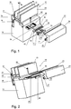
- Fig. 1 shows in a perspective, exploded view of a part of a provided with a disc (20) and generally 10 'designated window or door frame according to the invention.
- a disc (20) and generally 10 'designated window or door frame according to the invention.
- the frame of a wooden window In the here in Fig. 1 embodiment shown is the frame of a wooden window.
- Fig. 2 shows another, generally designated 10 'window or door frame in the same representation as in Fig. 1 but in a slightly different view. At the in Fig. 2 The embodiment shown is the frame of a wood-metal window.
- the embodiment according to Fig. 1 differs from the embodiment according to Fig. 2 Mainly in that the frame profile 12 is provided with a profile part 16 which in a fold of the frame profile 12 by means of a in the Fig. 10 - 13 fastener 14 is fixed, whereas the frame profile 12 'is externally provided with a profile part 16', which in the Fig. 12 and 14, 15 not shown in detail manner is attached to the frame section 12 '.
- an outer abutment portion 18 is formed for the disc 20 respectively.
- the disc 20 is in the embodiments of the Fig. 1 and 2 each of three individual glass panes, which are firmly connected.
- the disc 20 could instead also consist of eg two individual glass panes, as in Fig.
- the disc 20 has an in Fig. 1 indicated thickness D.
- the disc 20 rests on a web 19 of the profile part 12, from which it protrudes inwards with a projection U.
- the web 19 has an inside height H.
- a seal 21 is disposed between the disc 20 and the profile part 16.
- a seal 23 is arranged between the disk 20 and the glass strip 24.
- a gasket 27 is disposed inside between the frame section 12 and the glass strip 24.
- a glazing bead clip consisting of three parts, namely a glazing bead holder 22, a holding part 26 and a wedge 28. These three parts will now be described in more detail.
- the holding part 26, separately in Fig. 3 has a central hole 29, so it with the help of one in the Fig. 1 and 2 shown fastener 60 with the frame section 12 is firmly connected.
- Per glass bar 24, a selectable number of glazing bead clips can be used.
- the holding member 26 has a generally designated 30 profile device for supporting the glass strip holder 22, which is designed as a crenelated latching profile 36.
- the locking profile 36 is interrupted by two guide grooves 64, 66, the purpose of which is explained below, the locking profile could, however, extend continuously over the entire upper side of the holding part 26.
- the holding part 26 is designed for attachment and attachment to the frame profile 12, 12 'in an area adjacent to the disk 20, so that, in contrast to the above-described prior art, neither the disk 20 engages under the attachment area 18 still engages behind.
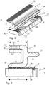
- the glass strip holder 22 is a part which is essentially U-shaped in cross-section and which is provided with two legs 42, 44, of which the leg 42 is provided with a profile device 34 which is designed as a crenelated latching profile 32.
- the leg 42 is provided with the locking profile 32.
- the locking profile 32 of the glass strip holder 22nd and the locking profile 36 of the holding part 26 are formed complementary to each other, so that they can be latched into each other in more than two selectable positions in a direction transverse to the disc 20 direction such as tongue and groove joints.
- Each crenellated locking profile 32, 36 consists of mutually alternating grooves and springs.
- a number of grooves and springs of a locking profile can be brought into engagement with a corresponding number of grooves and springs of the other locking profile, as best in eg Fig. 7 can be seen.
- the leg 44 is provided with an end face 50 for pressing against the disc 20. As shown in Fig. 7 the leg 42 has a length L 1 and the leg 44 has a length L 2 .
- the leg 42 is not normally brought into contact with the disc 20.
- the length L 2 of the leg 44 is selectable or adjustable in dependence on the contact pressure which is to be exerted on the disc 20 via the end face 50. For adjusting the length L 2 of the leg 44, it can be cut to the appropriate length.
- it is provided on its upper and lower surfaces with weakening lines 51, 52, which are formed as formed into the surface fine grooves with V-shaped cross-section.
- the leg 42 is provided on its underside with guide elements 54, 56 for engagement in guide grooves 64, 66 of the holding part 26 in the manner of a dovetail guide.
- guide elements 54, 56 for engagement in guide grooves 64, 66 of the holding part 26 in the manner of a dovetail guide.
- the holding part 26 and the glass strip holder 22 are fixed by a between the holding part 26 and the glass strip holder 22 retractable wedge 28, the best in Fig. 1 can be seen.
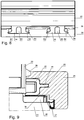
- the wedge 28 has pin elements 71 - 76 projecting from a transverse bolt 70, which can be received in a form-fitting manner in complementary cavities 81 - 86 delimited by one of the guide elements 54, 56 and one of the guide grooves 64, 66, as shown in FIGS Fig. 4 and 8th can be seen.
- the pin elements 71, 72 and 73, 74 are circular in cross section.
- the pin members 75 and 76 are rectangular in cross-section as shown in FIG Fig. 4 can be seen.
- the complementary cavities 81, 82 and 83, 84 and 85 and 86 are in Fig. 8 to recognize.
- the glass strip holder 22 For mounting the glass strip holder 22 in the illustration in Fig. 4 slightly raised and introduced with its guide elements 54, 56 in the guide grooves 64, 66, until the end face 50 rests with sufficient contact pressure on the disc 20. Subsequently, the glass strip holder 22 is lowered, wherein the latching profiles 32, 36 are snapped into one another. Subsequently, the wedge 28 between the glass strip holder 22 and the holding part 26 of a in Fig. 4 shown position in a in the 6 and 7 advanced position shown to secure the latching position.
- the glass strip holder 22 has a spring 46 arranged opposite to the two legs 42, 44 for positive and / or non-positive engagement in a retaining groove 25 of the glass strip 24.
- the mutual intervention is in Fig. 9 shown.
- the spring 46 is provided on its upper side with a barb-forming profiling, which makes it difficult to pull out the spring 46 from the groove 25.
- the two legs 42, 44 are interconnected by a U or connecting web 43, on which the spring 46 is formed.
- the fully assembled window or door frame 10, 10 ' is in the Fig. 10 - 13 or 14 and 15 respectively in cross-section and for different disc and frame profile thicknesses and in cross section differently shaped frame sections 12, 12 'and glazing beads 24 and each adapted thereto cross-sectional shape of the glass strip holder 22 shown.
- the lengths L 1 and L 2 of the legs 42 and 44 of the glass strip holder 22 are the same size.
- the length L 2 is always equal to the length L 1 or less than the length L 1 , but if it allows the frame profile or the glass strip, it is possible to choose L 2 greater than L 1 .
- the projection U of the disc 20 and the web height H are chosen so that the leg 42 does not touch the disc 20.
- the values of the supernatant U and the height H can be chosen so that the holding part 26 partially engages under the disc 20, but without touching it. Much more remains between the bottom of the disc 20 and the top of the holding part 26 at least enough space that the leg 42 of the glass strip holder 22 can engage under the disc, but without touching it, as in the FIGS. 12 and 13 is shown. In this case, the length L 2 of the leg 44 is shortened accordingly, so that a very flat glass bar 24 as in Fig. 13 can be used.
- the FIGS. 14 and 15 show corresponding variants with respect to the frame profile 12 '.
Landscapes
- Engineering & Computer Science (AREA)
- Civil Engineering (AREA)
- Structural Engineering (AREA)
- Securing Of Glass Panes Or The Like (AREA)
Claims (6)
- Cadre de fenêtre ou de porte ,- avec un profilé de cadre (12, 12'), qui est doté d'une zone extérieure d'appui (18) pour un vitrage (20),- avec au moins un support de parclose (22) disposé sur le côté du vitrage (20) opposé à la zone d'appui (18) pour appuyer la vitre (20) sur la zone d'appui (18),- avec une parclose (24) disposée sur le support de parclose (22), recouvrant au moins en partie le support de parclose (22), et- avec au moins une pièce de maintien (26) reliée fermement au profilé de cadre (12, 12') avec un dispositif profilé (30) adapté à plusieurs épaisseurs du vitrage pour soutenir le support de parclose (22),- la ou chaque pièce de maintien (26) et le ou chaque support de parclose (22) comportant respectivement un dispositif profilé (30, 34) constitué comme un profilé d'encliquetage crénelé (32, 36) et- les profilés d'encliquetage (32, 36) étant constitués de façon complémentaire l'un par rapport à l'autre et pouvant être encliquetés l'un dans l'autre dans plus de deux positions sélectionnables s'étendant dans une direction transversalement au vitrage (20) et- le support de parclose (22) étant constitué en section pour l'essentiel en forme de U et étant doté de deux branches (42, 44) dont une branche (42) est dotée du profilé d'encliquetage (32) pour encliquetage dans le profilé d'encliquetage (36) de la pièce de maintien et dont au moins l'autre branche (44) est dotée d'une face frontale (50) pour appuyer au vitrage (20),caractérisé en ce qu'- une branche (42) est dotée d'éléments de guidage (54, 56) à la manière d'un guidage en queue d'aronde pour engagement dans les rainures de guidage (64, 66) de la pièce de maintien (26) et- en ce que la pièce de maintien (26) et le support de parclose (22) sont fixés par un coin (28) inséré entre la pièce de maintien (26) et le support de parclose (22) lorsque les profilés d'encliquetage (32, 36) sont enclenchés l'un dans l'autre.
- Cadre de fenêtre ou de porte selon la revendication 1, caractérisé en ce que la longueur (L2) de l'autre branche (44) peut être choisie ou réglée.
- Cadre de fenêtre ou de porte selon la revendication 1 ou 2, caractérisé en ce que le coin (28) comporte des éléments à tiges (71 - 76) ressortant d'une targette transversale (70), qui peuvent être logés par conformité de forme dans des espaces creux (81 - 86) complémentaires limités respectivement par un des éléments de guidage (54, 56) et une des rainures de guidage (64, 66).
- Cadre de fenêtre ou de porte selon l'une quelconque des revendications 1 à 3, caractérisé en ce que le support de parclose (22) comporte un ressort (46) disposé opposé aux deux branches (42, 44) pour un engagement par conformité de forme et/ou de force dans une rainure de maintien (25) de la parclose (24).
- Cadre de fenêtre ou de porte selon l'une quelconque des revendications précédentes, caractérisé en ce qu'au moins une pièce de maintien (26) est attribuée au ou à chaque support de parclose (22) et en ce que la ou chaque pièce de maintien (26) peut être fixée au profilé de cadre (12, 12') en une position sélectionnable au moyen d'une attache de maintien (60).
- Cadre de fenêtre ou de porte selon la revendication 5, caractérisé en ce que la pièce de maintien (26) est constituée dans une zone proche du vitrage (20) pour fixation et montage sur le profilé de cadre (12, 12').
Applications Claiming Priority (1)
| Application Number | Priority Date | Filing Date | Title |
|---|---|---|---|
| DE102010060672.3A DE102010060672B4 (de) | 2010-11-19 | 2010-11-19 | Fenster- oder Türrahmen |
Publications (3)
| Publication Number | Publication Date |
|---|---|
| EP2455574A2 EP2455574A2 (fr) | 2012-05-23 |
| EP2455574A3 EP2455574A3 (fr) | 2017-01-11 |
| EP2455574B1 true EP2455574B1 (fr) | 2018-03-14 |
Family
ID=45023511
Family Applications (1)
| Application Number | Title | Priority Date | Filing Date |
|---|---|---|---|
| EP11009046.1A Not-in-force EP2455574B1 (fr) | 2010-11-19 | 2011-11-15 | Cadre de fenêtre ou de porte |
Country Status (2)
| Country | Link |
|---|---|
| EP (1) | EP2455574B1 (fr) |
| DE (1) | DE102010060672B4 (fr) |
Families Citing this family (3)
| Publication number | Priority date | Publication date | Assignee | Title |
|---|---|---|---|---|
| EP3396097A1 (fr) | 2017-04-24 | 2018-10-31 | SFS Intec Holding AG | Fixation de vitrage isolant et procédé de fixation |
| DE202017106284U1 (de) * | 2017-10-17 | 2017-11-13 | Zuani Deutschland Gmbh | Festverglasungssystem zur Fixierung einer Glashalteleiste mit definierbarem Anpressdruck |
| CA3221824A1 (fr) * | 2022-12-02 | 2024-06-02 | Andersen Corporation | Dispositif d~autoserrage pour une unite de fenestration |
Family Cites Families (8)
| Publication number | Priority date | Publication date | Assignee | Title |
|---|---|---|---|---|
| DE2521514A1 (de) * | 1975-05-14 | 1976-11-25 | Albrecht Gmbh Stahl Und Metall | Vorrichtung zur befestigung einer abdeckleiste an einem rahmen fuer fenster u.dgl. |
| GB2051197A (en) * | 1979-06-13 | 1981-01-14 | Blacknell Buildings Ltd | Window Mounting Assembly |
| US4702050A (en) * | 1984-06-27 | 1987-10-27 | Donat Flamand, Inc. | Casing window |
| DE3441444A1 (de) * | 1984-11-13 | 1986-05-22 | Fa. Otto Haas, 8500 Nürnberg | Glashalteleiste |
| GB9424555D0 (en) * | 1994-12-06 | 1995-01-25 | Chattin Peter J | Retention device |
| GB2306996B (en) * | 1995-11-02 | 1999-09-15 | Ravenscroft Plastics | A system for mounting a panel within a surrounding frame |
| DE10119446B4 (de) * | 2001-04-20 | 2008-07-10 | Unilux Ag | Fenster- oder Türrahmen |
| EP2078814A3 (fr) * | 2008-01-10 | 2010-03-10 | G.T. Windows Limited | Dispositif de fixation d'un cadre de fenêtre dans une ouverture au moyen d'un méchanisme à cliquet |
-
2010
- 2010-11-19 DE DE102010060672.3A patent/DE102010060672B4/de not_active Expired - Fee Related
-
2011
- 2011-11-15 EP EP11009046.1A patent/EP2455574B1/fr not_active Not-in-force
Non-Patent Citations (1)
| Title |
|---|
| None * |
Also Published As
| Publication number | Publication date |
|---|---|
| EP2455574A2 (fr) | 2012-05-23 |
| DE102010060672A1 (de) | 2012-05-24 |
| EP2455574A3 (fr) | 2017-01-11 |
| DE102010060672B4 (de) | 2016-09-15 |
Similar Documents
| Publication | Publication Date | Title |
|---|---|---|
| DE102011107589B4 (de) | Schutzgitter sowie Eckverbinder hierfür | |
| DE102009012438A1 (de) | Pfostenverbinder | |
| EP2816172A2 (fr) | Système de montage pour un revêtement de sol | |
| EP2354419A2 (fr) | Connecteur de rembourrage | |
| EP2455574B1 (fr) | Cadre de fenêtre ou de porte | |
| EP2128366B1 (fr) | Armature pour porte coulissante | |
| WO2015074933A1 (fr) | Dispositif de retenue pour boîtier et procédé de montage du boîtier à l'aide du dispositif de retenue | |
| EP2754803B1 (fr) | Crémone de fenêtre ou de porte et tringle pour une telle crémone | |
| AT500181B1 (de) | Tür- oder fensterbeschlag | |
| DE202009003438U1 (de) | Pfostenverbinder | |
| EP1186723B1 (fr) | Dispositif de fixation pour une façade avec montants et traverses | |
| DE202008015077U1 (de) | Adapter zur Befestigung von Solarmodulen, mit Adapter befestigte Solarmodule und Werkzeug zum Lösen der Befestigung | |
| DE202004004703U1 (de) | Rahmen für eine Tür, ein Fenster o.dgl. | |
| EP2067906B1 (fr) | Système de connexion pour tiges de profil en forme de cannelure et agencement de connexion | |
| DE29803656U1 (de) | Tür- oder Fensterbeschlag | |
| EP4286635B1 (fr) | Rail de coulissement pour un entraînement de porte | |
| DE202013012004U1 (de) | Rahmensystem für ein Partikelschutzgitter | |
| DE102008057276A1 (de) | Adapter zur Befestigung von Solarmodulen, mit Adaptern befestigte Solarmodule und Verfahren zur Befestigung von Solarmodulen | |
| EP2136027B1 (fr) | Raccordement d'angle pour cadre de porte et de fenêtre | |
| EP2090789B1 (fr) | Connecteur pour tiges de profil en forme de cannelure et agencement de connexion | |
| DE102007009667A1 (de) | Profilkonstruktion | |
| DE29502101U1 (de) | Verbindung von flächigen, miteinander fluchtenden Planteilen | |
| DE10354310A1 (de) | Dichtung insbesondere selbsttätig absenkende Bodendichtung für Türen | |
| DE8712001U1 (de) | Halterungselement | |
| EP0933480A2 (fr) | Réservoir de chasse d'eau |
Legal Events
| Date | Code | Title | Description |
|---|---|---|---|
| PUAI | Public reference made under article 153(3) epc to a published international application that has entered the european phase |
Free format text: ORIGINAL CODE: 0009012 |
|
| AK | Designated contracting states |
Kind code of ref document: A2 Designated state(s): AL AT BE BG CH CY CZ DE DK EE ES FI FR GB GR HR HU IE IS IT LI LT LU LV MC MK MT NL NO PL PT RO RS SE SI SK SM TR |
|
| AX | Request for extension of the european patent |
Extension state: BA ME |
|
| PUAL | Search report despatched |
Free format text: ORIGINAL CODE: 0009013 |
|
| AK | Designated contracting states |
Kind code of ref document: A3 Designated state(s): AL AT BE BG CH CY CZ DE DK EE ES FI FR GB GR HR HU IE IS IT LI LT LU LV MC MK MT NL NO PL PT RO RS SE SI SK SM TR |
|
| AX | Request for extension of the european patent |
Extension state: BA ME |
|
| RIC1 | Information provided on ipc code assigned before grant |
Ipc: E06B 3/58 20060101AFI20161202BHEP Ipc: E06B 3/54 20060101ALI20161202BHEP |
|
| 17P | Request for examination filed |
Effective date: 20170616 |
|
| RBV | Designated contracting states (corrected) |
Designated state(s): AL AT BE BG CH CY CZ DE DK EE ES FI FR GB GR HR HU IE IS IT LI LT LU LV MC MK MT NL NO PL PT RO RS SE SI SK SM TR |
|
| GRAP | Despatch of communication of intention to grant a patent |
Free format text: ORIGINAL CODE: EPIDOSNIGR1 |
|
| INTG | Intention to grant announced |
Effective date: 20171207 |
|
| GRAS | Grant fee paid |
Free format text: ORIGINAL CODE: EPIDOSNIGR3 |
|
| GRAA | (expected) grant |
Free format text: ORIGINAL CODE: 0009210 |
|
| AK | Designated contracting states |
Kind code of ref document: B1 Designated state(s): AL AT BE BG CH CY CZ DE DK EE ES FI FR GB GR HR HU IE IS IT LI LT LU LV MC MK MT NL NO PL PT RO RS SE SI SK SM TR |
|
| REG | Reference to a national code |
Ref country code: GB Ref legal event code: FG4D Free format text: NOT ENGLISH |
|
| REG | Reference to a national code |
Ref country code: CH Ref legal event code: EP Ref country code: AT Ref legal event code: REF Ref document number: 979057 Country of ref document: AT Kind code of ref document: T Effective date: 20180315 |
|
| REG | Reference to a national code |
Ref country code: IE Ref legal event code: FG4D Free format text: LANGUAGE OF EP DOCUMENT: GERMAN |
|
| REG | Reference to a national code |
Ref country code: DE Ref legal event code: R096 Ref document number: 502011013883 Country of ref document: DE |
|
| REG | Reference to a national code |
Ref country code: NL Ref legal event code: MP Effective date: 20180314 |
|
| REG | Reference to a national code |
Ref country code: LT Ref legal event code: MG4D |
|
| PG25 | Lapsed in a contracting state [announced via postgrant information from national office to epo] |
Ref country code: FI Free format text: LAPSE BECAUSE OF FAILURE TO SUBMIT A TRANSLATION OF THE DESCRIPTION OR TO PAY THE FEE WITHIN THE PRESCRIBED TIME-LIMIT Effective date: 20180314 Ref country code: NO Free format text: LAPSE BECAUSE OF FAILURE TO SUBMIT A TRANSLATION OF THE DESCRIPTION OR TO PAY THE FEE WITHIN THE PRESCRIBED TIME-LIMIT Effective date: 20180614 Ref country code: HR Free format text: LAPSE BECAUSE OF FAILURE TO SUBMIT A TRANSLATION OF THE DESCRIPTION OR TO PAY THE FEE WITHIN THE PRESCRIBED TIME-LIMIT Effective date: 20180314 Ref country code: LT Free format text: LAPSE BECAUSE OF FAILURE TO SUBMIT A TRANSLATION OF THE DESCRIPTION OR TO PAY THE FEE WITHIN THE PRESCRIBED TIME-LIMIT Effective date: 20180314 Ref country code: ES Free format text: LAPSE BECAUSE OF FAILURE TO SUBMIT A TRANSLATION OF THE DESCRIPTION OR TO PAY THE FEE WITHIN THE PRESCRIBED TIME-LIMIT Effective date: 20180314 Ref country code: CY Free format text: LAPSE BECAUSE OF FAILURE TO SUBMIT A TRANSLATION OF THE DESCRIPTION OR TO PAY THE FEE WITHIN THE PRESCRIBED TIME-LIMIT Effective date: 20180314 |
|
| PG25 | Lapsed in a contracting state [announced via postgrant information from national office to epo] |
Ref country code: GR Free format text: LAPSE BECAUSE OF FAILURE TO SUBMIT A TRANSLATION OF THE DESCRIPTION OR TO PAY THE FEE WITHIN THE PRESCRIBED TIME-LIMIT Effective date: 20180615 Ref country code: LV Free format text: LAPSE BECAUSE OF FAILURE TO SUBMIT A TRANSLATION OF THE DESCRIPTION OR TO PAY THE FEE WITHIN THE PRESCRIBED TIME-LIMIT Effective date: 20180314 Ref country code: SE Free format text: LAPSE BECAUSE OF FAILURE TO SUBMIT A TRANSLATION OF THE DESCRIPTION OR TO PAY THE FEE WITHIN THE PRESCRIBED TIME-LIMIT Effective date: 20180314 Ref country code: BG Free format text: LAPSE BECAUSE OF FAILURE TO SUBMIT A TRANSLATION OF THE DESCRIPTION OR TO PAY THE FEE WITHIN THE PRESCRIBED TIME-LIMIT Effective date: 20180614 Ref country code: RS Free format text: LAPSE BECAUSE OF FAILURE TO SUBMIT A TRANSLATION OF THE DESCRIPTION OR TO PAY THE FEE WITHIN THE PRESCRIBED TIME-LIMIT Effective date: 20180314 |
|
| PG25 | Lapsed in a contracting state [announced via postgrant information from national office to epo] |
Ref country code: MT Free format text: LAPSE BECAUSE OF FAILURE TO SUBMIT A TRANSLATION OF THE DESCRIPTION OR TO PAY THE FEE WITHIN THE PRESCRIBED TIME-LIMIT Effective date: 20180314 |
|
| PG25 | Lapsed in a contracting state [announced via postgrant information from national office to epo] |
Ref country code: NL Free format text: LAPSE BECAUSE OF FAILURE TO SUBMIT A TRANSLATION OF THE DESCRIPTION OR TO PAY THE FEE WITHIN THE PRESCRIBED TIME-LIMIT Effective date: 20180314 Ref country code: PL Free format text: LAPSE BECAUSE OF FAILURE TO SUBMIT A TRANSLATION OF THE DESCRIPTION OR TO PAY THE FEE WITHIN THE PRESCRIBED TIME-LIMIT Effective date: 20180314 Ref country code: EE Free format text: LAPSE BECAUSE OF FAILURE TO SUBMIT A TRANSLATION OF THE DESCRIPTION OR TO PAY THE FEE WITHIN THE PRESCRIBED TIME-LIMIT Effective date: 20180314 Ref country code: AL Free format text: LAPSE BECAUSE OF FAILURE TO SUBMIT A TRANSLATION OF THE DESCRIPTION OR TO PAY THE FEE WITHIN THE PRESCRIBED TIME-LIMIT Effective date: 20180314 Ref country code: IT Free format text: LAPSE BECAUSE OF FAILURE TO SUBMIT A TRANSLATION OF THE DESCRIPTION OR TO PAY THE FEE WITHIN THE PRESCRIBED TIME-LIMIT Effective date: 20180314 Ref country code: RO Free format text: LAPSE BECAUSE OF FAILURE TO SUBMIT A TRANSLATION OF THE DESCRIPTION OR TO PAY THE FEE WITHIN THE PRESCRIBED TIME-LIMIT Effective date: 20180314 |
|
| PG25 | Lapsed in a contracting state [announced via postgrant information from national office to epo] |
Ref country code: CZ Free format text: LAPSE BECAUSE OF FAILURE TO SUBMIT A TRANSLATION OF THE DESCRIPTION OR TO PAY THE FEE WITHIN THE PRESCRIBED TIME-LIMIT Effective date: 20180314 Ref country code: SM Free format text: LAPSE BECAUSE OF FAILURE TO SUBMIT A TRANSLATION OF THE DESCRIPTION OR TO PAY THE FEE WITHIN THE PRESCRIBED TIME-LIMIT Effective date: 20180314 Ref country code: SK Free format text: LAPSE BECAUSE OF FAILURE TO SUBMIT A TRANSLATION OF THE DESCRIPTION OR TO PAY THE FEE WITHIN THE PRESCRIBED TIME-LIMIT Effective date: 20180314 |
|
| REG | Reference to a national code |
Ref country code: DE Ref legal event code: R097 Ref document number: 502011013883 Country of ref document: DE |
|
| PG25 | Lapsed in a contracting state [announced via postgrant information from national office to epo] |
Ref country code: PT Free format text: LAPSE BECAUSE OF FAILURE TO SUBMIT A TRANSLATION OF THE DESCRIPTION OR TO PAY THE FEE WITHIN THE PRESCRIBED TIME-LIMIT Effective date: 20180716 |
|
| PLBE | No opposition filed within time limit |
Free format text: ORIGINAL CODE: 0009261 |
|
| STAA | Information on the status of an ep patent application or granted ep patent |
Free format text: STATUS: NO OPPOSITION FILED WITHIN TIME LIMIT |
|
| PG25 | Lapsed in a contracting state [announced via postgrant information from national office to epo] |
Ref country code: DK Free format text: LAPSE BECAUSE OF FAILURE TO SUBMIT A TRANSLATION OF THE DESCRIPTION OR TO PAY THE FEE WITHIN THE PRESCRIBED TIME-LIMIT Effective date: 20180314 |
|
| 26N | No opposition filed |
Effective date: 20181217 |
|
| PG25 | Lapsed in a contracting state [announced via postgrant information from national office to epo] |
Ref country code: SI Free format text: LAPSE BECAUSE OF FAILURE TO SUBMIT A TRANSLATION OF THE DESCRIPTION OR TO PAY THE FEE WITHIN THE PRESCRIBED TIME-LIMIT Effective date: 20180314 |
|
| GBPC | Gb: european patent ceased through non-payment of renewal fee |
Effective date: 20181115 |
|
| PG25 | Lapsed in a contracting state [announced via postgrant information from national office to epo] |
Ref country code: LU Free format text: LAPSE BECAUSE OF NON-PAYMENT OF DUE FEES Effective date: 20181115 Ref country code: MC Free format text: LAPSE BECAUSE OF FAILURE TO SUBMIT A TRANSLATION OF THE DESCRIPTION OR TO PAY THE FEE WITHIN THE PRESCRIBED TIME-LIMIT Effective date: 20180314 |
|
| REG | Reference to a national code |
Ref country code: BE Ref legal event code: MM Effective date: 20181130 |
|
| REG | Reference to a national code |
Ref country code: IE Ref legal event code: MM4A |
|
| PG25 | Lapsed in a contracting state [announced via postgrant information from national office to epo] |
Ref country code: IE Free format text: LAPSE BECAUSE OF NON-PAYMENT OF DUE FEES Effective date: 20181115 Ref country code: FR Free format text: LAPSE BECAUSE OF NON-PAYMENT OF DUE FEES Effective date: 20181130 |
|
| PG25 | Lapsed in a contracting state [announced via postgrant information from national office to epo] |
Ref country code: BE Free format text: LAPSE BECAUSE OF NON-PAYMENT OF DUE FEES Effective date: 20181130 |
|
| PG25 | Lapsed in a contracting state [announced via postgrant information from national office to epo] |
Ref country code: GB Free format text: LAPSE BECAUSE OF NON-PAYMENT OF DUE FEES Effective date: 20181115 |
|
| PG25 | Lapsed in a contracting state [announced via postgrant information from national office to epo] |
Ref country code: TR Free format text: LAPSE BECAUSE OF FAILURE TO SUBMIT A TRANSLATION OF THE DESCRIPTION OR TO PAY THE FEE WITHIN THE PRESCRIBED TIME-LIMIT Effective date: 20180314 |
|
| PG25 | Lapsed in a contracting state [announced via postgrant information from national office to epo] |
Ref country code: MK Free format text: LAPSE BECAUSE OF NON-PAYMENT OF DUE FEES Effective date: 20180314 Ref country code: HU Free format text: LAPSE BECAUSE OF FAILURE TO SUBMIT A TRANSLATION OF THE DESCRIPTION OR TO PAY THE FEE WITHIN THE PRESCRIBED TIME-LIMIT; INVALID AB INITIO Effective date: 20111115 |
|
| PG25 | Lapsed in a contracting state [announced via postgrant information from national office to epo] |
Ref country code: IS Free format text: LAPSE BECAUSE OF FAILURE TO SUBMIT A TRANSLATION OF THE DESCRIPTION OR TO PAY THE FEE WITHIN THE PRESCRIBED TIME-LIMIT Effective date: 20180714 |
|
| PGFP | Annual fee paid to national office [announced via postgrant information from national office to epo] |
Ref country code: DE Payment date: 20201125 Year of fee payment: 10 Ref country code: AT Payment date: 20201117 Year of fee payment: 10 |
|
| PGFP | Annual fee paid to national office [announced via postgrant information from national office to epo] |
Ref country code: CH Payment date: 20211004 Year of fee payment: 11 |
|
| REG | Reference to a national code |
Ref country code: DE Ref legal event code: R119 Ref document number: 502011013883 Country of ref document: DE |
|
| REG | Reference to a national code |
Ref country code: AT Ref legal event code: MM01 Ref document number: 979057 Country of ref document: AT Kind code of ref document: T Effective date: 20211115 |
|
| PG25 | Lapsed in a contracting state [announced via postgrant information from national office to epo] |
Ref country code: AT Free format text: LAPSE BECAUSE OF NON-PAYMENT OF DUE FEES Effective date: 20211115 |
|
| PG25 | Lapsed in a contracting state [announced via postgrant information from national office to epo] |
Ref country code: DE Free format text: LAPSE BECAUSE OF NON-PAYMENT OF DUE FEES Effective date: 20220601 |
|
| REG | Reference to a national code |
Ref country code: CH Ref legal event code: PL |
|
| PG25 | Lapsed in a contracting state [announced via postgrant information from national office to epo] |
Ref country code: LI Free format text: LAPSE BECAUSE OF NON-PAYMENT OF DUE FEES Effective date: 20221130 Ref country code: CH Free format text: LAPSE BECAUSE OF NON-PAYMENT OF DUE FEES Effective date: 20221130 |