EP2455830A1 - Procédé destiné à la détection de modifications de signaux d'entrée - Google Patents
Procédé destiné à la détection de modifications de signaux d'entrée Download PDFInfo
- Publication number
- EP2455830A1 EP2455830A1 EP10192213A EP10192213A EP2455830A1 EP 2455830 A1 EP2455830 A1 EP 2455830A1 EP 10192213 A EP10192213 A EP 10192213A EP 10192213 A EP10192213 A EP 10192213A EP 2455830 A1 EP2455830 A1 EP 2455830A1
- Authority
- EP
- European Patent Office
- Prior art keywords
- input
- output module
- time stamp
- clock
- signal
- Prior art date
- Legal status (The legal status is an assumption and is not a legal conclusion. Google has not performed a legal analysis and makes no representation as to the accuracy of the status listed.)
- Ceased
Links
Images

Classifications
-
- G—PHYSICS
- G05—CONTROLLING; REGULATING
- G05B—CONTROL OR REGULATING SYSTEMS IN GENERAL; FUNCTIONAL ELEMENTS OF SUCH SYSTEMS; MONITORING OR TESTING ARRANGEMENTS FOR SUCH SYSTEMS OR ELEMENTS
- G05B19/00—Program-control systems
- G05B19/02—Program-control systems electric
- G05B19/04—Program control other than numerical control, i.e. in sequence controllers or logic controllers
- G05B19/05—Programmable logic controllers, e.g. simulating logic interconnections of signals according to ladder diagrams or function charts
- G05B19/054—Input/output
-
- G—PHYSICS
- G05—CONTROLLING; REGULATING
- G05B—CONTROL OR REGULATING SYSTEMS IN GENERAL; FUNCTIONAL ELEMENTS OF SUCH SYSTEMS; MONITORING OR TESTING ARRANGEMENTS FOR SUCH SYSTEMS OR ELEMENTS
- G05B19/00—Program-control systems
- G05B19/02—Program-control systems electric
- G05B19/04—Program control other than numerical control, i.e. in sequence controllers or logic controllers
- G05B19/042—Program control other than numerical control, i.e. in sequence controllers or logic controllers using digital processors
- G05B19/0423—Input/output
Definitions
- the invention relates to a method for detecting input signal changes at an input of an input / output module, which is operated in an automation system, while a signal is sampled via the input / output module, wherein at a signal change, a change event and a time stamp associated with this change event is created, and the value pair change event and time stamp is stored in a higher-level automation component of the input / output module.
- input / output modules are preferably connected via an interface module.
- Signal and signal changes from digital or analog peripherals are analyzed, recorded and provided with a time via these input / output modules.
- the time is designed as a so-called timestamp.
- An example of such an input signal change is a change of a binary input signal or a state change or the like.
- a change in the input signal is also to be understood as exceeding a limit value of an analog signal.
- the time stamped in the time stamp is thus the time of day the clock in the interface module at the moment of transfer of the user data from the peripheral assembly, preferably the input / output module, and thereby differs at the time of real detection of the signal on the peripheral assembly or input / output module.
- each input / output module requires an implementation or hardware for a high-precision clock.
- the determination of the time stamp is not accurate enough.
- the object is achieved in the method mentioned above in that the input / output module and the higher-level automation component are operated isochronous with a clock to each other, the time stamp is calculated centrally due to the isochronous operation on the higher-level automation component.
- the isochronous processing of inputs and outputs it is possible to increase the accuracy for the detection of peripheral signal changes by means of these synchronized processes.
- an isochronous data transmission is selected for the automation system.
- a higher-level automation component can stamp the changed data itself because it can calculate the time of the change.
- an addition of a current time at the time of the clock and a multiple of a sample interval in the input / output module results in the time stamp.
- the signal is sampled at a frequency in the input / output module, the frequency resulting from the division of the clock interval by the sampling interval.
- the clock interval is the time interval between two synchronization clocks.
- a number which corresponds to the frequency is buffered at sampled values in the input / output module and transmitted to the higher-level automation component, wherein the higher-level automation component is used to check on the basis of the row of values at which value a signal change occurred is, where the position of the value within the row gives the multiple for the calculation of the time stamp.
- a number which corresponds to the frequency is buffered at sampled values in the input / output module and checked in the input / output module on the basis of the series of values at which value a signal change has occurred of the value within the series results in the multiple for the calculation of the time stamp and this is transmitted to the higher-level automation component.
- an edge detector is operated in the input / output module, which detects when a signal change takes place and for each sampled value in the input / output module, a counter is counted up, wherein upon detection of an edge by the edge detector a count of the counter results in multiples for the calculation of the time stamp and this is transmitted to the higher-level automation component.
- the edge detection in the input / output module is performed analogously, whereby the sampling interval is chosen smaller and improves the accuracy of the time stamp calculation.
- the edge detector is constructed with discrete components.
- a clock is operated in the higher-level automation component, which provides the instantaneous time, while this clock is synchronized with other automation components in the automation system.
- the higher-level automation component is operated as an interface module and the input / output module sends the detected values to the interface module via a peripheral bus, wherein the interface module in turn is operated on a fieldbus which is connected to an automation device.
- FIG. 1 is an automation system 1 comprising an automation device 50, a field bus 13, an interface module 11, a peripheral bus 12 and an input / output module 2 with an input 3 for signals 4 shown.
- an automation system 1 a programmable control system, a programmable logic controller with a via a field bus 13 connected decentralized periphery or a personal computer, in particular for process automation, be.
- a sensor which leads into an industrial process is connected via the input 3 of the input / output module 2. So that later in the automation device 50 or in a turn higher-level control system can be accurately determined at what time the signal of the sensor, for example, from “0" to “1”, ie from "OFF” to "ON” or "door closed” Door on “, a method for detecting input signal changes at the input 3 of the input / output module 2 is applied.
- the signal 4 is sampled via the input 3, the sampling in the detection means 23 is performed by an oversampling method known to those skilled in the art.
- a clock divider 25 is configured to receive the synchronous clock T and from the synchronous clock T by a reduction diminished clock 24 to produce.
- the clock T has a clock interval of 100 ⁇ s, and thus the decimated clock T has a sampling interval I of 10 ⁇ s.
- time synchronization telegrams 22 are sent to all automation components in the automation system 1.
- the time synchronization telegram 22, which arrives via the field bus 13 to the interface module 11, is received by a clock 9.
- This clock 9 is considered a synchronized via the fieldbus 13 high-precision clock.
- the synchronized time in the clock 9 is used in the interface module 11 to drive a clock generator 20, which generates the clock T.
- the clock generator 20 is connected to the clock divider 25 of the input / output module 2.
- a change event 5 is transmitted via the peripheral bus 12 to the interface module 11.
- the change event reaches a means 21 for time stamping. Since the input / output module 2 and the interface module 11 are operated isochronous to each other, the time stamp 6 can be calculated centrally on the interface module 11 due to the isochronous operation. For this calculation, a frequency K to be sampled is used. The frequency K results from the division of the clock interval by the sampling interval I.
- a number which corresponds to the frequency K is temporarily stored in the input / output module 2 at sampled values in the input / output module 2 and transmitted via the peripheral bus 12 to the interface module 11.
- the means 21 for time stamping in the interface module 11 is designed such that it is checked on the basis of the series of values at which value a signal change has occurred, the position of the value within the row resulting in the multiple for the calculation of the time stamp.
- a telegram is generated in the means 21 for time stamping, which contains the time stamp 6, the current value of the signal 4a and the change event, this telegram can be sent via the fieldbus 13.
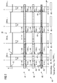
- the flowchart 40 shows a signal curve of the signal 4.
- the signal curve has as input signal changes flanks 10, which rise or fall alternately.
- the clock T is represented as a synchronization pulse with a vertical dashed line through the diagram.
- the clock interval in cycle N is considered in more detail. Due to the reduced clock 24, so the oversampling in the input / output module 2, arise in the clock interval of 100 microseconds several 10 microseconds slices, namely a first 10 microseconds interval I 1 to a tenth 10 microseconds interval I 10 .
- the time slices of 10 ⁇ s each are numbered from 1 to 10.
- the input / output module 2 can now recognize a new value every 10 ⁇ s and store it in an internal buffer (oversampling).
- the means 21 for timestamping a delta-t can determine the time stamp in which a signal change actually took place because of the granularity of the 10 ⁇ s slices. This results in a much higher accuracy than is the case in the prior art.
- the detection torque 44 in which a signal change has been detected is shown as a bold black arrow. Based on the waveform of the signal 4 with the rising edge 10 leads from the rising edge a dashed vertical line down to the first variant 41. Exactly at this point is due to the rising edge 10, a signal change instead. However, this signal change was detected only after the expiry of the 10 ⁇ s slice, resulting in a detection error 45 and a delta t n .
- a second variant 42 would also be conceivable, in this second variant 42 a number which corresponds to the frequency K is buffered at sampled values in the input / output module 2 and checked in the input / output module 2 on the basis of the series of values which value a signal change has occurred, the position of the value within the series being the multiple for the calculation of the Time stamp 6 results and this multiple is transmitted to the interface module 11 for the means 21 for time stamping.
- a third variant 43 provides that in the input / output module 2 (see FIG. 1 ), an edge detector 7 is operated, which detects when a signal change takes place and for each sampled value in the input / output module 2 counts up a counter 8. Upon detection of an edge 10 by the edge detector 7, the counter reading of the counter 8 becomes the multiple for the calculation of the time stamp 6. This multiple or the counter reading is thus transmitted to the interface module 11 via the peripheral bus 12 and used in the means 21 for time stamping calculation ,
- the edge detection represents the change event 5.
- t cycle_n corresponds to the instantaneous time.
- the t offsett could be a propagation delay on the peripheral bus 12.
Landscapes
- Physics & Mathematics (AREA)
- General Physics & Mathematics (AREA)
- Engineering & Computer Science (AREA)
- Automation & Control Theory (AREA)
- Arrangements For Transmission Of Measured Signals (AREA)
- Small-Scale Networks (AREA)
Priority Applications (3)
| Application Number | Priority Date | Filing Date | Title |
|---|---|---|---|
| EP10192213A EP2455830A1 (fr) | 2010-11-23 | 2010-11-23 | Procédé destiné à la détection de modifications de signaux d'entrée |
| US13/303,301 US8775852B2 (en) | 2010-11-23 | 2011-11-23 | Method for sensing input signal changes |
| CN2011103767204A CN102478796A (zh) | 2010-11-23 | 2011-11-23 | 探测输入信号变化的方法 |
Applications Claiming Priority (1)
| Application Number | Priority Date | Filing Date | Title |
|---|---|---|---|
| EP10192213A EP2455830A1 (fr) | 2010-11-23 | 2010-11-23 | Procédé destiné à la détection de modifications de signaux d'entrée |
Publications (1)
| Publication Number | Publication Date |
|---|---|
| EP2455830A1 true EP2455830A1 (fr) | 2012-05-23 |
Family
ID=43558041
Family Applications (1)
| Application Number | Title | Priority Date | Filing Date |
|---|---|---|---|
| EP10192213A Ceased EP2455830A1 (fr) | 2010-11-23 | 2010-11-23 | Procédé destiné à la détection de modifications de signaux d'entrée |
Country Status (3)
| Country | Link |
|---|---|
| US (1) | US8775852B2 (fr) |
| EP (1) | EP2455830A1 (fr) |
| CN (1) | CN102478796A (fr) |
Families Citing this family (3)
| Publication number | Priority date | Publication date | Assignee | Title |
|---|---|---|---|---|
| KR101583421B1 (ko) | 2014-06-16 | 2016-01-07 | 홍상현 | 전동 유축기 |
| EP3242466B1 (fr) * | 2016-05-04 | 2019-04-17 | Siemens Aktiengesellschaft | Procédé de configuration de dispositifs de communication d'un système d'automatisation industriel et unité de distribution de données de configuration |
| JP6794919B2 (ja) * | 2017-04-28 | 2020-12-02 | 横河電機株式会社 | プロセス制御システム及びデータ処理方法 |
Citations (9)
| Publication number | Priority date | Publication date | Assignee | Title |
|---|---|---|---|---|
| EP1184755A2 (fr) * | 2000-08-18 | 2002-03-06 | Siemens Aktiengesellschaft | Méthode de fonctionnement d'une unité périphérique comprenant un groupe de tête et au moins un groupe d'entrée |
| EP1219520A2 (fr) * | 2000-12-22 | 2002-07-03 | Jürgen Dipl.-Ing. Hank (FH) | Appareil et méthode pour le transmission de données de mesure |
| DE10147421A1 (de) * | 2001-03-16 | 2002-09-26 | Siemens Ag | Anwendungen eines schaltbaren Datennetzes für Echtzeit- und Nichtechtzeitkommunikation |
| DE10321652A1 (de) * | 2003-05-13 | 2004-12-02 | Tentaclion Gmbh | Modulares Datenerfassungs-und Übertragungssystem sowie Übertragungseinrichtung dafür |
| DE102004050386A1 (de) * | 2004-10-15 | 2006-05-04 | Siemens Ag | Verfahren und Einrichtung zur Analyse eines technischen Prozesses |
| DE102006010748A1 (de) | 2006-03-08 | 2007-09-13 | Pepperl + Fuchs Gmbh | Verfahren zum Aufzeichnen von Eingangssignaländerungen |
| EP1981243A1 (fr) * | 2007-04-13 | 2008-10-15 | E-Senza Technologies GmbH | Système de réseau de communication de données pour communication de données sans fil bidirectionnelle multicanaux |
| EP2085841A1 (fr) * | 2008-01-31 | 2009-08-05 | Sick Ag | Capteur avec temporisateur à émettre le temps de détection d' un objet |
| DE102009017681A1 (de) * | 2009-04-16 | 2010-10-28 | Phoenix Contact Gmbh & Co. Kg | Verfahren und Kommunikationssystem zum Ermitteln des Zeitpunktes eines Ereignisses in einem IO-Gerät |
Family Cites Families (25)
| Publication number | Priority date | Publication date | Assignee | Title |
|---|---|---|---|---|
| US5486864A (en) * | 1993-05-13 | 1996-01-23 | Rca Thomson Licensing Corporation | Differential time code method and apparatus as for a compressed video signal |
| US5600576A (en) * | 1994-03-11 | 1997-02-04 | Northrop Grumman Corporation | Time stress measurement device |
| US6584163B1 (en) * | 1998-06-01 | 2003-06-24 | Agere Systems Inc. | Shared data and clock recovery for packetized data |
| US6845416B1 (en) * | 2000-08-02 | 2005-01-18 | National Instruments Corporation | System and method for interfacing a CAN device and a peripheral device |
| US7028204B2 (en) * | 2000-09-06 | 2006-04-11 | Schneider Automation Inc. | Method and apparatus for ethernet prioritized device clock synchronization |
| US7251199B2 (en) * | 2001-12-24 | 2007-07-31 | Agilent Technologies, Inc. | Distributed system time synchronization including a timing signal path |
| JP3995552B2 (ja) * | 2002-07-23 | 2007-10-24 | 松下電器産業株式会社 | クロック逓倍回路 |
| DE10249886B4 (de) * | 2002-10-25 | 2005-02-10 | Sp3D Chip Design Gmbh | Verfahren und Vorrichtung zum Erzeugen eines Taktsignals mit vorbestimmten Taktsingaleigenschaften |
| TWI300892B (en) * | 2003-04-01 | 2008-09-11 | Faraday Tech Corp | Method of synchronizing dual clock frequencies |
| US20050149631A1 (en) * | 2004-01-07 | 2005-07-07 | Schneider Automation Sas | Safety Modbus Protocol |
| JP2005250683A (ja) * | 2004-03-02 | 2005-09-15 | Renesas Technology Corp | マイクロコンピュータ |
| SE528607C2 (sv) * | 2004-04-30 | 2006-12-27 | Kvaser Consultant Ab | System och anordning för att tidsmässigt relatera händelser i ett fordon |
| US7203610B2 (en) * | 2004-08-31 | 2007-04-10 | Guide Technology, Inc. | System and method of obtaining data-dependent jitter (DDJ) estimates from measured signal data |
| WO2006119378A2 (fr) * | 2005-05-03 | 2006-11-09 | Pinpoint Tracking Solutions, Llc | Systeme et procede d'interfaçage avec un reseau de commande d'un vehicule |
| US7573914B2 (en) * | 2005-05-12 | 2009-08-11 | Agilent Technologies, Inc. | Systems and methods for synchronizing time across networks |
| US7325152B2 (en) * | 2005-06-30 | 2008-01-29 | Infineon Technologies Ag | Synchronous signal generator |
| JP4756954B2 (ja) * | 2005-08-29 | 2011-08-24 | ルネサスエレクトロニクス株式会社 | クロックアンドデータリカバリ回路 |
| US7574632B2 (en) * | 2005-09-23 | 2009-08-11 | Teradyne, Inc. | Strobe technique for time stamping a digital signal |
| US20100292825A1 (en) * | 2006-08-09 | 2010-11-18 | Auckland Uniservices Limited | Process control of an industrial plant |
| US7680063B2 (en) * | 2006-11-10 | 2010-03-16 | Motorola, Inc. | Method and apparatus for synchronizing transmissions from multiple transmitters |
| US7835814B2 (en) * | 2007-08-16 | 2010-11-16 | International Business Machines Corporation | Tool for reporting the status and drill-down of a control application in an automated manufacturing environment |
| US7657333B2 (en) * | 2007-09-27 | 2010-02-02 | Rockwell Automation Technologies, Inc. | Adjustment of data collection rate based on anomaly detection |
| US20090180783A1 (en) * | 2008-01-11 | 2009-07-16 | Tellabs Petaluma, Inc. | Method, network, apparatus and computer program for using leaky counters in clock and data recovery circuits |
| US8468270B2 (en) * | 2009-12-11 | 2013-06-18 | General Electric Company | Method, system, and apparatus for archiving networked data |
| CN102413055A (zh) * | 2011-12-19 | 2012-04-11 | 曙光信息产业(北京)有限公司 | 一种软硬件结合实现的报文时间戳标记系统和方法 |
-
2010
- 2010-11-23 EP EP10192213A patent/EP2455830A1/fr not_active Ceased
-
2011
- 2011-11-23 CN CN2011103767204A patent/CN102478796A/zh active Pending
- 2011-11-23 US US13/303,301 patent/US8775852B2/en not_active Expired - Fee Related
Patent Citations (9)
| Publication number | Priority date | Publication date | Assignee | Title |
|---|---|---|---|---|
| EP1184755A2 (fr) * | 2000-08-18 | 2002-03-06 | Siemens Aktiengesellschaft | Méthode de fonctionnement d'une unité périphérique comprenant un groupe de tête et au moins un groupe d'entrée |
| EP1219520A2 (fr) * | 2000-12-22 | 2002-07-03 | Jürgen Dipl.-Ing. Hank (FH) | Appareil et méthode pour le transmission de données de mesure |
| DE10147421A1 (de) * | 2001-03-16 | 2002-09-26 | Siemens Ag | Anwendungen eines schaltbaren Datennetzes für Echtzeit- und Nichtechtzeitkommunikation |
| DE10321652A1 (de) * | 2003-05-13 | 2004-12-02 | Tentaclion Gmbh | Modulares Datenerfassungs-und Übertragungssystem sowie Übertragungseinrichtung dafür |
| DE102004050386A1 (de) * | 2004-10-15 | 2006-05-04 | Siemens Ag | Verfahren und Einrichtung zur Analyse eines technischen Prozesses |
| DE102006010748A1 (de) | 2006-03-08 | 2007-09-13 | Pepperl + Fuchs Gmbh | Verfahren zum Aufzeichnen von Eingangssignaländerungen |
| EP1981243A1 (fr) * | 2007-04-13 | 2008-10-15 | E-Senza Technologies GmbH | Système de réseau de communication de données pour communication de données sans fil bidirectionnelle multicanaux |
| EP2085841A1 (fr) * | 2008-01-31 | 2009-08-05 | Sick Ag | Capteur avec temporisateur à émettre le temps de détection d' un objet |
| DE102009017681A1 (de) * | 2009-04-16 | 2010-10-28 | Phoenix Contact Gmbh & Co. Kg | Verfahren und Kommunikationssystem zum Ermitteln des Zeitpunktes eines Ereignisses in einem IO-Gerät |
Also Published As
| Publication number | Publication date |
|---|---|
| US20120131373A1 (en) | 2012-05-24 |
| CN102478796A (zh) | 2012-05-30 |
| US8775852B2 (en) | 2014-07-08 |
Similar Documents
| Publication | Publication Date | Title |
|---|---|---|
| DE102015119511B4 (de) | Apparat und Verfahren zur Signalsynchronisation | |
| EP2526431B1 (fr) | Procédé et dispositif de contrôle d'un signal de fréquence | |
| DE102011008227A1 (de) | Verfahren und Systeme zum Messen von Datenimpulsen | |
| EP3298798B1 (fr) | Procédé et dispositif de synchronisation des capteurs | |
| EP1810096B1 (fr) | Procede pour echanger des donnees entre des terminaux de differents reseaux | |
| EP3526930B1 (fr) | Procédé de surveillance d'un réseau pour des anomalies | |
| EP0258231B1 (fr) | Appareil de traitement de signaux | |
| EP1315337B1 (fr) | Interface du bus | |
| DE102014113162B4 (de) | Verfahren für einen verbesserten Datendurchsatz in einem Kommunikationssystem und Kommunikationssystem | |
| EP2455830A1 (fr) | Procédé destiné à la détection de modifications de signaux d'entrée | |
| EP2072964A2 (fr) | Procédé et dispositif d'établissement de valeurs de mesure à partir d'un déroulement dépendant du temps | |
| DE102013213087A1 (de) | Überwachungsschaltung mit einem fenster-watchdog | |
| EP1738185B1 (fr) | Dispositif de traitement de signaux avec declenchement synchron | |
| DE102012003909B4 (de) | Verfahren zur Verwendung in einem Sigma-Delta-Analog-Digital-Wandler, Sigma-Delta-Analog-Digital-Wandler und Systeme mit einem Sigma-Delta-Analog-Digital-Wandler | |
| EP2299614B1 (fr) | Dispositif et procédé de synchronisation temporelle dans un réseau de communication | |
| DE102009026641A1 (de) | Verfahren zum Betreiben eines Datenübertragungssystems, Datenübertragungssystem und Computerprogrammprodukt | |
| EP2932634B1 (fr) | Attribution d' horodatage aux pacquets de données recus | |
| EP2287693B1 (fr) | Procédé d'acquisition et d'enregistrement synchrones de données de processus et/ou d'état et système d'automatisation | |
| EP2149979B1 (fr) | Procédé de détermination de la valeur de mesure dans un système commandé de manière cadencée | |
| EP2434360A1 (fr) | Système de contrôle de mouvement | |
| WO1994007148A1 (fr) | Procede de balayage pour signaux de gigue | |
| DE102013111711B4 (de) | Verfahren zur positionsgesteuerten Messwert-Erfassung in Echtzeit | |
| EP1393084B1 (fr) | Dispositif de mesure de frequence | |
| DE102015002170A1 (de) | Verfahren für eine deterministische Auswahl eines Sensors aus einer Vielzahl von Sensoren | |
| EP1850195A1 (fr) | Procédé et dispositif pour tester un commande de moteur et dispositif de commande de moteur adapté |
Legal Events
| Date | Code | Title | Description |
|---|---|---|---|
| PUAI | Public reference made under article 153(3) epc to a published international application that has entered the european phase |
Free format text: ORIGINAL CODE: 0009012 |
|
| AK | Designated contracting states |
Kind code of ref document: A1 Designated state(s): AL AT BE BG CH CY CZ DE DK EE ES FI FR GB GR HR HU IE IS IT LI LT LU LV MC MK MT NL NO PL PT RO RS SE SI SK SM TR |
|
| AX | Request for extension of the european patent |
Extension state: BA ME |
|
| 17P | Request for examination filed |
Effective date: 20121123 |
|
| RAP1 | Party data changed (applicant data changed or rights of an application transferred) |
Owner name: SIEMENS AKTIENGESELLSCHAFT |
|
| 17Q | First examination report despatched |
Effective date: 20130611 |
|
| STAA | Information on the status of an ep patent application or granted ep patent |
Free format text: STATUS: THE APPLICATION HAS BEEN REFUSED |
|
| 18R | Application refused |
Effective date: 20140425 |