EP1184755A2 - Méthode de fonctionnement d'une unité périphérique comprenant un groupe de tête et au moins un groupe d'entrée - Google Patents
Méthode de fonctionnement d'une unité périphérique comprenant un groupe de tête et au moins un groupe d'entrée Download PDFInfo
- Publication number
- EP1184755A2 EP1184755A2 EP01119059A EP01119059A EP1184755A2 EP 1184755 A2 EP1184755 A2 EP 1184755A2 EP 01119059 A EP01119059 A EP 01119059A EP 01119059 A EP01119059 A EP 01119059A EP 1184755 A2 EP1184755 A2 EP 1184755A2
- Authority
- EP
- European Patent Office
- Prior art keywords
- process data
- input module
- head assembly
- module
- operating method
- Prior art date
- Legal status (The legal status is an assumption and is not a legal conclusion. Google has not performed a legal analysis and makes no representation as to the accuracy of the status listed.)
- Granted
Links
Images

Classifications
-
- G—PHYSICS
- G05—CONTROLLING; REGULATING
- G05B—CONTROL OR REGULATING SYSTEMS IN GENERAL; FUNCTIONAL ELEMENTS OF SUCH SYSTEMS; MONITORING OR TESTING ARRANGEMENTS FOR SUCH SYSTEMS OR ELEMENTS
- G05B19/00—Program-control systems
- G05B19/02—Program-control systems electric
- G05B19/04—Program control other than numerical control, i.e. in sequence controllers or logic controllers
- G05B19/042—Program control other than numerical control, i.e. in sequence controllers or logic controllers using digital processors
Definitions
- the present invention relates to an operating method for one from a head assembly and at least one input assembly existing peripheral control unit, being from the input module Process data read into the input module and then provided to the head assembly, wherein the head assembly matches the process data provided Assigned timestamp.
- Peripheral control unit consisting of a head assembly and - usually several - there are input and output modules e.g. known for PROFIBUS systems. You form one like that named DP slave.
- the individual components of the Peripheral control unit asynchronous. Edit in particular the input modules their entire cycle including all Diagnoses and further processing come to an end and make only then your process data are ready for the head assembly. This then reads at the appropriate point in their own machining cycle the process data into the head module, checks them for signal changes and saves them in the event of a change with that at the time of reading into the head assembly valid time.
- This procedure can lead to deviations between the stored Time and the time at which the process data in the Input module were read in by several milliseconds to lead.
- the object of the present invention is a inexpensive and effective operating method for a a head assembly and at least one input assembly To create peripheral control unit, by means of which an exact time stamp assignment to the imported process data is possible.
- the task is solved by the input module a signal signal promptly for reading in the process data the head assembly is communicated and that the head assembly determines the time stamp based on the receipt of the message signal.
- the transmission of the alarm signal is high priority and the provision the process data is given a low priority, it is guaranteed that the message signal is always timely to read the Process data is transmitted to the head assembly.
- the alarm signal of the head module is via its own alarm signal line is transmitted, the transmission of the Message signals also during the exchange of process data between other modules of the peripheral control unit.
- the process data read into the input module are preprocessed by the input module and the message signal is only transmitted to the head assembly if the input module needs to be updated due to the preprocessing for the process data is recognized, the process data exchange between the input module and the Head assembly kept as low as possible.
- the preprocessing the process data preferably includes in particular also a plausibility check of the input module read process data.
- the peripheral control unit is usually in a larger size Automation system integrated.
- the head assembly provides the process data therefore usually for a higher-level one Central unit ready.
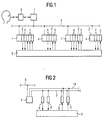
- FIG 1 there is a distributed automation system in usually from a higher-level central unit 1 and more Peripheral control unit 2.
- the central unit 1 and the Peripheral control unit 2 communicate via, for example a serial fieldbus 3, e.g. according to the PROFIBUS protocol, together.
- the peripheral control unit 2 exists - see also FIG 2 - each from a head module 4, input modules 5 and Output modules 6.
- the modules 4-6 of each peripheral control unit 2 are interconnected via a control unit bus 7 connected.
- the control unit bus 7 can optionally be a serial one or a parallel bus 7.
- the input and output modules 5, 6 read process data cyclically from a technical system 8 to be controlled Process data to this. You provide the read Process data ready for the head modules 4. There will be the A time stamp is assigned to process data and a - at least partially - further processing. If necessary the process data from the head modules 4 to the Central unit 1 forwarded.
- the central unit 1 communicates usually via a suitable interface 9, z. B. a computer monitor with an input keyboard and a Mouse, with one user.
- the head assemblies 4 each have a microprocessor 10 on.
- As part of the processing of the computer program product 11 communicates the head assembly 4 with the Central unit 1 and the input and output modules assigned to it 5, 6.
- the head assembly 4 also has a buffer 12 and a timer 13.
- the buffer 12 is used for Buffering of process data and one of the process data if applicable, assigned time stamp.
- the timestamp is determined by querying the timer 13.
- the microprocessor 10 can be seen on the one hand with the serial Fieldbus 3 and on the other hand with the control unit bus 7 connected.
- the control unit bus 7 has its own Signaling signal line 14 via which a signaling signal can be transmitted which will be discussed in more detail later becomes.
- each input module 5 has a microcontroller 15 on.
- the microcontroller 15 also works Computer program product 16 starting the operation of the input module 5 controls.
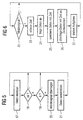
- the microcontroller 15 first reads according to a step 17 Process data from the technical system to be controlled 8 in the respective input module 5. Then the microcontroller takes 15 in steps 18 and 19 preprocessing the process data read into the input module 5. In particular the microcontroller checks in step 18 whether the Process data as such are possible. So he takes one Plausibility check. Step 19 then checks whether whether the process data is different from that of the previous cycle have changed the read process data. Only if the process data are both plausible and there has been a change , subsequent steps 20, 21 are carried out.
- step 20 could also take place before Check for plausibility and / or changes.
- step 20 immediately, that is, promptly for reading a process signal in the input module 5 the head assembly 4 transmitted.
- the transmission of the message signal takes place with high priority via the signaling line 14.
- step 21 the read process data for the head assembly 4 provided.
- the process data is provided at a low priority at the process data interface of the rest of the control unit bus 7, i.e. without paying attention to the signal signal line 14th
- Steps 17 to 21 are usually processed cyclically. After the processing of step 21 started again with the processing of step 17.
- the head assembly 4 generally operates its program cyclically from. 6, this includes steps 22 in particular until 27.
- Step 22 a query is made as to whether a signal from a the input modules 5 was transmitted. If so, in Step 23 records the time by querying the timer 13, a timestamp is determined. Get the timestamp takes place immediately after receipt of the notification signal. The determined time stamp is stored in the buffer 12 deposited.
- step 24 the corresponding process data queried by the signaling input module 5.
- the process data are also stored in the buffer store 12.
- the previously determined time stamp is assigned to you. If necessary, the imported process data and the time stamp assigned to them in step 26 provided for the higher-level central unit 1. Further in step 27 further tasks are carried out, which in the context of the present invention are not of concern. After that the process continues with step 22.
- the operating method according to the invention is without additional Hardware expenditure compared to the prior art and with only very little additional software effort a significant increase in the state of the art Accuracy of the timestamp achievable.
- the Accuracy of the timestamp is now independent of the delay between reading the process data and making it available the process data and also regardless of the transmission duration.
Landscapes
- Physics & Mathematics (AREA)
- General Physics & Mathematics (AREA)
- Engineering & Computer Science (AREA)
- Automation & Control Theory (AREA)
- Programmable Controllers (AREA)
- Computer And Data Communications (AREA)
- Control By Computers (AREA)
- Seats For Vehicles (AREA)
- Electrophonic Musical Instruments (AREA)
- Heating, Cooling, Or Curing Plastics Or The Like In General (AREA)
- Communication Control (AREA)
Applications Claiming Priority (2)
| Application Number | Priority Date | Filing Date | Title |
|---|---|---|---|
| DE10040468A DE10040468A1 (de) | 2000-08-18 | 2000-08-18 | Betriebsverfahren für eine aus einer Kopfbaugruppe und mindestens einer Eingabebaugruppe bestehende Peripheriesteuereinheit |
| DE10040468 | 2000-08-18 |
Publications (3)
| Publication Number | Publication Date |
|---|---|
| EP1184755A2 true EP1184755A2 (fr) | 2002-03-06 |
| EP1184755A3 EP1184755A3 (fr) | 2006-07-19 |
| EP1184755B1 EP1184755B1 (fr) | 2008-03-19 |
Family
ID=7652905
Family Applications (1)
| Application Number | Title | Priority Date | Filing Date |
|---|---|---|---|
| EP01119059A Expired - Lifetime EP1184755B1 (fr) | 2000-08-18 | 2001-08-07 | Méthode de fonctionnement d'une unité périphérique comprenant un groupe de tête et au moins un groupe d'entrée |
Country Status (4)
| Country | Link |
|---|---|
| EP (1) | EP1184755B1 (fr) |
| AT (1) | ATE389906T1 (fr) |
| DE (2) | DE10040468A1 (fr) |
| ES (1) | ES2299453T3 (fr) |
Cited By (3)
| Publication number | Priority date | Publication date | Assignee | Title |
|---|---|---|---|---|
| FR2848313A1 (fr) * | 2002-12-06 | 2004-06-11 | Avensy | Perfectionnement a un systeme de suivi de production assiste par ordinateur |
| WO2007101658A1 (fr) * | 2006-03-08 | 2007-09-13 | Pepperl + Fuchs Gmbh | Procédé d'enregistrement des modifications de signaux d'entrée |
| EP2455830A1 (fr) * | 2010-11-23 | 2012-05-23 | Siemens Aktiengesellschaft | Procédé destiné à la détection de modifications de signaux d'entrée |
Families Citing this family (1)
| Publication number | Priority date | Publication date | Assignee | Title |
|---|---|---|---|---|
| DE102009017681B4 (de) * | 2009-04-16 | 2014-02-20 | Phoenix Contact Gmbh & Co. Kg | Verfahren und Kommunikationssystem zum Ermitteln des Zeitpunktes eines Ereignisses in einem IO-Gerät |
Family Cites Families (5)
| Publication number | Priority date | Publication date | Assignee | Title |
|---|---|---|---|---|
| US4550382A (en) * | 1982-09-21 | 1985-10-29 | Xerox Corporation | Filtered inputs |
| DE4408488A1 (de) * | 1994-03-14 | 1995-09-21 | Bosch Gmbh Robert | Verfahren zur zyklischen Übertragung von Daten zwischen mindestens zwei verteilt arbeitenden Steuergeräten |
| WO1996001979A1 (fr) * | 1994-07-07 | 1996-01-25 | Westinghouse Electric Corporation | Appareil attribuant une heure d'apparition a des signaux de capteur |
| US5933347A (en) * | 1997-06-13 | 1999-08-03 | Allen-Bradley Company Llc | Industrial controller with program synchronized updating of back-up controller |
| US6173207B1 (en) * | 1997-09-22 | 2001-01-09 | Agilent Technologies, Inc. | Real-time control system with non-deterministic communication |
-
2000
- 2000-08-18 DE DE10040468A patent/DE10040468A1/de not_active Ceased
-
2001
- 2001-08-07 EP EP01119059A patent/EP1184755B1/fr not_active Expired - Lifetime
- 2001-08-07 ES ES01119059T patent/ES2299453T3/es not_active Expired - Lifetime
- 2001-08-07 AT AT01119059T patent/ATE389906T1/de not_active IP Right Cessation
- 2001-08-07 DE DE50113746T patent/DE50113746D1/de not_active Expired - Lifetime
Cited By (5)
| Publication number | Priority date | Publication date | Assignee | Title |
|---|---|---|---|---|
| FR2848313A1 (fr) * | 2002-12-06 | 2004-06-11 | Avensy | Perfectionnement a un systeme de suivi de production assiste par ordinateur |
| WO2004053607A1 (fr) * | 2002-12-06 | 2004-06-24 | Avensy | Systeme de suivi de production assiste par ordinateur avec tracabilite des donnees de production |
| WO2007101658A1 (fr) * | 2006-03-08 | 2007-09-13 | Pepperl + Fuchs Gmbh | Procédé d'enregistrement des modifications de signaux d'entrée |
| EP2455830A1 (fr) * | 2010-11-23 | 2012-05-23 | Siemens Aktiengesellschaft | Procédé destiné à la détection de modifications de signaux d'entrée |
| US8775852B2 (en) | 2010-11-23 | 2014-07-08 | Siemens Aktiengesellschaft | Method for sensing input signal changes |
Also Published As
| Publication number | Publication date |
|---|---|
| EP1184755A3 (fr) | 2006-07-19 |
| DE50113746D1 (de) | 2008-04-30 |
| DE10040468A1 (de) | 2002-03-07 |
| ATE389906T1 (de) | 2008-04-15 |
| EP1184755B1 (fr) | 2008-03-19 |
| ES2299453T3 (es) | 2008-06-01 |
Similar Documents
| Publication | Publication Date | Title |
|---|---|---|
| EP0678796B1 (fr) | Automate programmable compact et unité centrale d'un automate programmable modulaire | |
| EP2621193B1 (fr) | Dispositif de transmission de données de capteur | |
| DE102014106752B4 (de) | Verfahren und Steuereinrichtung zum Betrieb eines berührungslosen Übertragungssystems für einen IO-Link | |
| DE102009045386A1 (de) | Verfahren zum Betreiben eines Feldbus-Interface | |
| EP3814856B1 (fr) | Dispositif d'automatisation en temps réel doté d'un bus de données en temps réel | |
| DE102007039425A1 (de) | Steuerknoten und Steuerung | |
| EP3019920B1 (fr) | Unité de détection de données et système d'automatisation | |
| WO2002075509A2 (fr) | Systeme de communication synchrone et cadence, comportant une horloge relative, et procede pour realiser un tel systeme | |
| EP0791874B1 (fr) | Méthode et dispositif de commande de capteurs et/ou actionneurs binaires | |
| EP2544388B1 (fr) | Procédé de synchronisation de la cadence de travail et du rythme dans un réseau d'automatisation | |
| EP1253494B1 (fr) | Système de commande et/ou de régulation comportant un bus de terrain | |
| EP1903530B1 (fr) | Agencement doté d'un appareil sous vide et son procédé de fonctionnement | |
| EP1184755B1 (fr) | Méthode de fonctionnement d'une unité périphérique comprenant un groupe de tête et au moins un groupe d'entrée | |
| EP2746892B1 (fr) | Installation automatisée et procédé de synchronisation d'une installation automatisée | |
| DE10131944A1 (de) | Verfahren zur Verarbeitung von Daten | |
| DE102010064123B3 (de) | Verfahren zum Ansteuern von Peripheriegeräten eines taktsynchron arbeitenden Bussystems und von Fremdperipheriegeräten eines Fremdbussystems sowie zugehöriger Busumsetzer | |
| DE10237097B4 (de) | Korrektur von Signallaufzeiten in verteilten Kommunikationssystemen | |
| EP2641210B1 (fr) | Contrôle de participants en réseau bus | |
| EP1802043A1 (fr) | Structure de communication | |
| WO2003046673A1 (fr) | Système d'ingenierie et système d'automatisation | |
| EP1170645A2 (fr) | Méthode et dispositif de surveillance et commande de machines, par exemple des installations industrielles | |
| EP1374000B1 (fr) | Procede et dispositif de commande et/ou de surveillance d'un dispositif surveillant la commande d'une installation | |
| EP2315090A1 (fr) | Méthode de commande en temps réel pour un dispositif de commande d'un processus industriel et méthode de commande en temps réel pour un ordinateur | |
| EP2287693A1 (fr) | Procédé d'acquisition et d'enregistrement synchrones de données de processus et/ou d'état et système d'automatisation | |
| DE29809721U1 (de) | Anordnung zur Steuerung und Regelung technischer Prozesse |
Legal Events
| Date | Code | Title | Description |
|---|---|---|---|
| PUAI | Public reference made under article 153(3) epc to a published international application that has entered the european phase |
Free format text: ORIGINAL CODE: 0009012 |
|
| AK | Designated contracting states |
Kind code of ref document: A2 Designated state(s): AT BE CH CY DE DK ES FI FR GB GR IE IT LI LU MC NL PT SE TR |
|
| AX | Request for extension of the european patent |
Free format text: AL;LT;LV;MK;RO;SI |
|
| PUAL | Search report despatched |
Free format text: ORIGINAL CODE: 0009013 |
|
| AK | Designated contracting states |
Kind code of ref document: A3 Designated state(s): AT BE CH CY DE DK ES FI FR GB GR IE IT LI LU MC NL PT SE TR |
|
| AX | Request for extension of the european patent |
Extension state: AL LT LV MK RO SI |
|
| 17P | Request for examination filed |
Effective date: 20060821 |
|
| AKX | Designation fees paid |
Designated state(s): AT CH DE ES FR GB LI |
|
| GRAP | Despatch of communication of intention to grant a patent |
Free format text: ORIGINAL CODE: EPIDOSNIGR1 |
|
| GRAS | Grant fee paid |
Free format text: ORIGINAL CODE: EPIDOSNIGR3 |
|
| GRAA | (expected) grant |
Free format text: ORIGINAL CODE: 0009210 |
|
| AK | Designated contracting states |
Kind code of ref document: B1 Designated state(s): AT CH DE ES FR GB LI |
|
| REG | Reference to a national code |
Ref country code: GB Ref legal event code: FG4D Free format text: NOT ENGLISH |
|
| GBT | Gb: translation of ep patent filed (gb section 77(6)(a)/1977) |
Effective date: 20080319 |
|
| REG | Reference to a national code |
Ref country code: CH Ref legal event code: NV Representative=s name: SIEMENS SCHWEIZ AG Ref country code: CH Ref legal event code: EP |
|
| REF | Corresponds to: |
Ref document number: 50113746 Country of ref document: DE Date of ref document: 20080430 Kind code of ref document: P |
|
| REG | Reference to a national code |
Ref country code: ES Ref legal event code: FG2A Ref document number: 2299453 Country of ref document: ES Kind code of ref document: T3 |
|
| ET | Fr: translation filed | ||
| PGFP | Annual fee paid to national office [announced via postgrant information from national office to epo] |
Ref country code: ES Payment date: 20080911 Year of fee payment: 8 |
|
| PGFP | Annual fee paid to national office [announced via postgrant information from national office to epo] |
Ref country code: AT Payment date: 20080709 Year of fee payment: 8 |
|
| PLBE | No opposition filed within time limit |
Free format text: ORIGINAL CODE: 0009261 |
|
| STAA | Information on the status of an ep patent application or granted ep patent |
Free format text: STATUS: NO OPPOSITION FILED WITHIN TIME LIMIT |
|
| PGFP | Annual fee paid to national office [announced via postgrant information from national office to epo] |
Ref country code: CH Payment date: 20081106 Year of fee payment: 8 |
|
| 26N | No opposition filed |
Effective date: 20081222 |
|
| REG | Reference to a national code |
Ref country code: CH Ref legal event code: PCAR Free format text: SIEMENS SCHWEIZ AG;INTELLECTUAL PROPERTY FREILAGERSTRASSE 40;8047 ZUERICH (CH) |
|
| REG | Reference to a national code |
Ref country code: CH Ref legal event code: PL |
|
| PG25 | Lapsed in a contracting state [announced via postgrant information from national office to epo] |
Ref country code: LI Free format text: LAPSE BECAUSE OF NON-PAYMENT OF DUE FEES Effective date: 20090831 Ref country code: CH Free format text: LAPSE BECAUSE OF NON-PAYMENT OF DUE FEES Effective date: 20090831 |
|
| PG25 | Lapsed in a contracting state [announced via postgrant information from national office to epo] |
Ref country code: AT Free format text: LAPSE BECAUSE OF NON-PAYMENT OF DUE FEES Effective date: 20090807 |
|
| REG | Reference to a national code |
Ref country code: ES Ref legal event code: FD2A Effective date: 20090808 |
|
| PG25 | Lapsed in a contracting state [announced via postgrant information from national office to epo] |
Ref country code: ES Free format text: LAPSE BECAUSE OF NON-PAYMENT OF DUE FEES Effective date: 20090808 |
|
| REG | Reference to a national code |
Ref country code: FR Ref legal event code: PLFP Year of fee payment: 16 |
|
| REG | Reference to a national code |
Ref country code: FR Ref legal event code: PLFP Year of fee payment: 17 |
|
| REG | Reference to a national code |
Ref country code: FR Ref legal event code: PLFP Year of fee payment: 18 |
|
| PGFP | Annual fee paid to national office [announced via postgrant information from national office to epo] |
Ref country code: FR Payment date: 20200813 Year of fee payment: 20 Ref country code: GB Payment date: 20200916 Year of fee payment: 20 |
|
| PGFP | Annual fee paid to national office [announced via postgrant information from national office to epo] |
Ref country code: DE Payment date: 20201019 Year of fee payment: 20 |
|
| REG | Reference to a national code |
Ref country code: DE Ref legal event code: R071 Ref document number: 50113746 Country of ref document: DE |
|
| REG | Reference to a national code |
Ref country code: GB Ref legal event code: PE20 Expiry date: 20210806 |
|
| PG25 | Lapsed in a contracting state [announced via postgrant information from national office to epo] |
Ref country code: GB Free format text: LAPSE BECAUSE OF EXPIRATION OF PROTECTION Effective date: 20210806 |