EP2456034A2 - Installation photovoltaïque et module photovoltaïque - Google Patents
Installation photovoltaïque et module photovoltaïque Download PDFInfo
- Publication number
- EP2456034A2 EP2456034A2 EP11189392A EP11189392A EP2456034A2 EP 2456034 A2 EP2456034 A2 EP 2456034A2 EP 11189392 A EP11189392 A EP 11189392A EP 11189392 A EP11189392 A EP 11189392A EP 2456034 A2 EP2456034 A2 EP 2456034A2
- Authority
- EP
- European Patent Office
- Prior art keywords
- photovoltaic
- module
- electronics
- string
- control signals
- Prior art date
- Legal status (The legal status is an assumption and is not a legal conclusion. Google has not performed a legal analysis and makes no representation as to the accuracy of the status listed.)
- Granted
Links
Images
Classifications
-
- H—ELECTRICITY
- H10—SEMICONDUCTOR DEVICES; ELECTRIC SOLID-STATE DEVICES NOT OTHERWISE PROVIDED FOR
- H10F—INORGANIC SEMICONDUCTOR DEVICES SENSITIVE TO INFRARED RADIATION, LIGHT, ELECTROMAGNETIC RADIATION OF SHORTER WAVELENGTH OR CORPUSCULAR RADIATION
- H10F77/00—Constructional details of devices covered by this subclass
- H10F77/95—Circuit arrangements
- H10F77/953—Circuit arrangements for devices having potential barriers
- H10F77/955—Circuit arrangements for devices having potential barriers for photovoltaic devices
-
- H—ELECTRICITY
- H02—GENERATION; CONVERSION OR DISTRIBUTION OF ELECTRIC POWER
- H02H—EMERGENCY PROTECTIVE CIRCUIT ARRANGEMENTS
- H02H1/00—Details of emergency protective circuit arrangements
- H02H1/06—Arrangements for supplying operative power
-
- Y—GENERAL TAGGING OF NEW TECHNOLOGICAL DEVELOPMENTS; GENERAL TAGGING OF CROSS-SECTIONAL TECHNOLOGIES SPANNING OVER SEVERAL SECTIONS OF THE IPC; TECHNICAL SUBJECTS COVERED BY FORMER USPC CROSS-REFERENCE ART COLLECTIONS [XRACs] AND DIGESTS
- Y02—TECHNOLOGIES OR APPLICATIONS FOR MITIGATION OR ADAPTATION AGAINST CLIMATE CHANGE
- Y02E—REDUCTION OF GREENHOUSE GAS [GHG] EMISSIONS, RELATED TO ENERGY GENERATION, TRANSMISSION OR DISTRIBUTION
- Y02E10/00—Energy generation through renewable energy sources
- Y02E10/50—Photovoltaic [PV] energy
Definitions
- the invention relates to a photovoltaic system with photovoltaic modules, each having at least one consisting of several solar panels panel string, wherein a plurality of photovoltaic modules are interconnected in series with module strands, and with an electronics for enabling photovoltaic modules whose supply voltage is generated by at least one of the photovoltaic modules.
- the invention also relates to a photovoltaic module, which is advantageously usable in particular within such a photovoltaic system.
- a photovoltaic system usually contains a plurality of photovoltaic modules of solar cells connected to one another in a manner known as panel strings, which are interconnected in series with module strings, also referred to as strings.
- the module strings deliver a DC voltage, which, usually after an adaptation of the voltage level by a DC-DC converter, is converted by means of an inverter into an AC voltage.
- the AC voltage supplied by the inverter can be fed into the grid of an energy supplier.
- Photovoltaic systems that have several module strings are, for example, from DE 199 19 766 A1 and the DE 101 36 147 B4 known.
- a problem of any photovoltaic generator is that it is almost an ideal power source as long as it is lit by the sun. This also means that further energy is generated in the event of fire or danger.
- Another possibility is to use the generated during solar irradiation of the module strands electrical energy for separating the current-carrying module strand in case of danger.
- disconnecting the module cords alone involves the risk of arcs occurring.
- an additional communication ring for example via radio links or additional lines, would be required in order to convey a reclosing information to the connection box.
- Such a photovoltaic system is in the German patent DE 10 2005 036 153 B4 described.
- the document discloses a protective switching device for a solar module in which the voltage drop across a bypass path is used in order to use a DC / DC booster circuit generate internal supply voltage.
- the circuitry required for this purpose is relatively expensive.
- Another disadvantage is that it is not possible with this protection circuit to disconnect the entire photovoltaic module at the outer terminals by shorting voltage, as this would eliminate the internal power supply.
- the switches controlling electronics can be supplied by a respective associated photovoltaic module with a voltage to perform a release in case of danger and a reconnection after the danger or allow.
- the power supply of the electronics remains in the unlocked state.
- the electronics can advantageously control the controllable switches in such a way that the respective photovoltaic module is always in the safe state. In the default state, the panel strings of the photovoltaic module are short-circuited, so that even with a malfunction of the electronics no danger can emanate from the photovoltaic module.
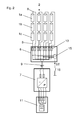
- FIG. 2 shows a block diagram, which is intended to illustrate the structure and operation of a photovoltaic system.
- the photovoltaic system has several module strands 2, each consisting of several, here by way of example three, connected in series photovoltaic modules 1 a, 1 b, 1 c, which are connected via module bus 8 with each other in series.
- the module string lines 8 are combined in a junction box 6 and connected to a main connection line 9, which is guided to the input terminal of a central inverter 7.
- the junction box 6 is here arranged spatially separated from the central inverter 7 and is preferably placed in the most favorable spatial position to the entirety of the module strands 2.
- the central inverter 7 has the function to convert the DC voltage generated by the photovoltaic modules 1 a, 1 b, 1 c in an AC voltage with a predetermined frequency. Downstream of the central inverter 7 is an AC switchgear cabinet 11, which couples the generated electrical energy into a voltage network.
- the central inverter 7 and the AC switchgear cabinet 11 can also form a structural unit with one another.
- the string fuses 10 can not eliminate hazards that arise due to high voltages on the module strands 2 itself. If, for example, a fire breaks out in a house with a photovoltaic system, the high voltages on the module strands 2 pose a danger to the life of the firefighters attacking the fire. Therefore, a possibility must be provided to switch the photovoltaic system safely in a safe manner.
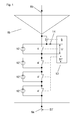
- the photovoltaic modules in the FIG. 1 sketched out construction. Shown is a single photovoltaic module 1 b from in the FIG. 2 illustrated block diagram, wherein preferably all in the FIG. 2 shown photovoltaic modules 1 a, 1 b, 1 c are constructed exactly the same.
- photovoltaic module 1 b has an integrated electronics 5 for controlling a plurality of controllable switches 3, 4, 4 '.
- the internal structure of the electronics 5 shown here only as a circuit block can either be limited to an arrangement of a few semiconductor switches or have an "intelligence" in the form of a simple microcontroller. In any case, it can be achieved that the electronics 5 contributes only slightly to the total costs of the photovoltaic module 1 b.
- the photovoltaic module 1 b has at least one and preferably a plurality of so-called panel strings 12, 12 ', which in each case consist of a series connection of a plurality of solar cells, not shown here.
- the panel strings 12, 12 ' are shown in simplified form here in each case by the circuit symbol of an electrical power source.
- a first panel string 12 in this case are two influenced by the electronics 5 controllable switch 3, 4, which are executable in circuit implementations as a semiconductor switch assigned.
- a controllable switch 4 ' is connected to the further panel strings 12', which bridges the associated panel string 12 'and thus short circuits it in the closed state.
- the first panel string 12 is connected via a polarity reversal protection diode 14 to inputs of the electronics 5 and provides this a supply voltage U available.
- the voltage and current requirement of the electronics 5 is dimensioned so that even with a shading, so only a low illumination of the panel string 12, this the electronics 5 can provide sufficient electrical energy.
- the circuit can advantageously be designed so that without a control by the electronics 5, all controllable switches 3, 4, 4 'are in the closed state, whereby all panel strings 12, 12' are short-circuited, and the photovoltaic module 1 b in a safe state.
- the electronics 5 controls the controllable switches 4 and 4 'in the open state and the controllable switch 3 in the closed state.
- all the panel strings 12, 12 ' are connected in series and connected both to the incoming and to the outgoing module string line 8a, 8b which connect the photovoltaic module 1b to adjacent photovoltaic modules 1a, 1c or to the junction box 6.
- the electronics 5 controls the controllable switches 4 and 4 'in the closed state and the controllable switch 3 in the open state.
- the panel strings 12 ' are each shorted and therefore harmless.
- the panel string 12 is the only one not short-circuited but continues to supply the supply voltage U for the electronics 5.
- the voltage U generated by the panel string 12 is removed by the open controllable switch 3 from the module strings 8a, 8b. It is also apparent that the all closed controllable switch 4 and 4 'make a direct conductive connection between the incoming and outgoing module string 8a, 8b, so that the photovoltaic module 1 b is voltage-free to the outside.
- control signals ST are provided which can be generated in various ways and passed on within the photovoltaic system.
- manually generated control signal ST can also be a shutdown of all photovoltaic modules 1 a, 1 b, 1 c are made in an emergency.
- the control signal ST can be supplied via radio links or via control lines 13 to the photovoltaic modules 1 a, 1 b, 1 c.
- a modulation device 15 can be provided in the junction box 6, which can simultaneously address all module string lines 8.
- the control signals ST reach the photovoltaic modules 1 a, 1 b, 1 c via the module string lines 8 and are forwarded internally either via the closed controllable switches 4, 4 'or via the illuminated and thus low-resistance panel strings 12, 12' and thus reach the electronics 5 in each photovoltaic module 1 a, 1 b, 1 c.
- the entire photovoltaic system can be switched off from a central point via an emergency switch 16. In the same simple way after the emergency situation and a restart of the photovoltaic system is possible.
Landscapes
- Photovoltaic Devices (AREA)
Priority Applications (1)
| Application Number | Priority Date | Filing Date | Title |
|---|---|---|---|
| PL11189392T PL2456034T3 (pl) | 2010-11-19 | 2011-11-16 | Instalacja fotowoltaiczna z modułami fotowoltaicznymi |
Applications Claiming Priority (1)
| Application Number | Priority Date | Filing Date | Title |
|---|---|---|---|
| DE102010052009A DE102010052009A1 (de) | 2010-11-19 | 2010-11-19 | Photovoltaikanlage und Photovoltaikmodul |
Publications (3)
| Publication Number | Publication Date |
|---|---|
| EP2456034A2 true EP2456034A2 (fr) | 2012-05-23 |
| EP2456034A3 EP2456034A3 (fr) | 2017-01-11 |
| EP2456034B1 EP2456034B1 (fr) | 2018-02-07 |
Family
ID=44992766
Family Applications (1)
| Application Number | Title | Priority Date | Filing Date |
|---|---|---|---|
| EP11189392.1A Active EP2456034B1 (fr) | 2010-11-19 | 2011-11-16 | Installation photovoltaïque et module photovoltaïque |
Country Status (5)
| Country | Link |
|---|---|
| EP (1) | EP2456034B1 (fr) |
| DE (1) | DE102010052009A1 (fr) |
| DK (1) | DK2456034T3 (fr) |
| ES (1) | ES2668225T3 (fr) |
| PL (1) | PL2456034T3 (fr) |
Cited By (3)
| Publication number | Priority date | Publication date | Assignee | Title |
|---|---|---|---|---|
| WO2014011392A3 (fr) * | 2012-07-09 | 2014-04-10 | Dow Global Technologies Llc | Systèmes et procédés pour détecter des discontinuités dans un circuit de réseau solaire et raccorder un flux de courant dans celui-ci |
| WO2014085468A1 (fr) * | 2012-11-29 | 2014-06-05 | Dow Global Technologies Llc | Systèmes et procédés de baisse de potentiel électrique dans des systèmes photovoltaïques |
| CN114978031A (zh) * | 2022-07-15 | 2022-08-30 | 苏州恩易浦科技有限公司 | 一种光伏板组串控制器、光伏供电装置及其控制方法 |
Families Citing this family (1)
| Publication number | Priority date | Publication date | Assignee | Title |
|---|---|---|---|---|
| DE102011107297A1 (de) | 2011-07-15 | 2013-01-17 | Kostal Industrie Elektrik Gmbh | Photovoltaikmodul und Photovoltaikanlage |
Citations (3)
| Publication number | Priority date | Publication date | Assignee | Title |
|---|---|---|---|---|
| DE19919766A1 (de) | 1999-04-29 | 2000-11-02 | Sma Regelsysteme Gmbh | Wechselrichter für eine Photovoltaik-Anlage |
| DE10136147B4 (de) | 2001-07-25 | 2004-11-04 | Kolm, Hendrik, Dipl.-Ing. | Photovoltaischer Wechselstromerzeuger |
| DE102005036153B4 (de) | 2005-05-24 | 2007-03-22 | Fraunhofer-Gesellschaft zur Förderung der angewandten Forschung e.V. | Schutzschalteinrichtung für ein Solarmodul |
Family Cites Families (9)
| Publication number | Priority date | Publication date | Assignee | Title |
|---|---|---|---|---|
| US6653549B2 (en) * | 2000-07-10 | 2003-11-25 | Canon Kabushiki Kaisha | Photovoltaic power generation systems and methods of controlling photovoltaic power generation systems |
| WO2008077473A2 (fr) * | 2006-12-21 | 2008-07-03 | Sp Solarprojekt Gmbh | Installation pour la production d'énergie solaire |
| DE102007032605A1 (de) * | 2007-07-11 | 2009-02-05 | Robert Maier | Fotovoltaikanlage |
| US8933321B2 (en) * | 2009-02-05 | 2015-01-13 | Tigo Energy, Inc. | Systems and methods for an enhanced watchdog in solar module installations |
| EP3496258B1 (fr) * | 2007-12-05 | 2025-02-05 | Solaredge Technologies Ltd. | Mécanismes de sécurité dans des installations de puissance réparties |
| DE102008014129B4 (de) * | 2008-03-13 | 2009-12-31 | Moeller Gmbh | Schutzvorrichtung für Solarpanels |
| DE102008052037B3 (de) * | 2008-10-16 | 2010-04-08 | Moeller Gmbh | Solarmodul |
| DE102009019831A1 (de) * | 2009-05-04 | 2010-11-11 | Voltwerk Electronics Gmbh | Schaltungsanordnung |
| DE102009044695A1 (de) * | 2009-11-27 | 2011-06-01 | Müller, Ingo, Dr. | Solarmodul, Modulschalter, Solarkabel, Sammelschiene, Mehrfachkontakt-Steckverbinder |
-
2010
- 2010-11-19 DE DE102010052009A patent/DE102010052009A1/de not_active Withdrawn
-
2011
- 2011-11-16 DK DK11189392.1T patent/DK2456034T3/da active
- 2011-11-16 EP EP11189392.1A patent/EP2456034B1/fr active Active
- 2011-11-16 ES ES11189392.1T patent/ES2668225T3/es active Active
- 2011-11-16 PL PL11189392T patent/PL2456034T3/pl unknown
Patent Citations (3)
| Publication number | Priority date | Publication date | Assignee | Title |
|---|---|---|---|---|
| DE19919766A1 (de) | 1999-04-29 | 2000-11-02 | Sma Regelsysteme Gmbh | Wechselrichter für eine Photovoltaik-Anlage |
| DE10136147B4 (de) | 2001-07-25 | 2004-11-04 | Kolm, Hendrik, Dipl.-Ing. | Photovoltaischer Wechselstromerzeuger |
| DE102005036153B4 (de) | 2005-05-24 | 2007-03-22 | Fraunhofer-Gesellschaft zur Förderung der angewandten Forschung e.V. | Schutzschalteinrichtung für ein Solarmodul |
Cited By (3)
| Publication number | Priority date | Publication date | Assignee | Title |
|---|---|---|---|---|
| WO2014011392A3 (fr) * | 2012-07-09 | 2014-04-10 | Dow Global Technologies Llc | Systèmes et procédés pour détecter des discontinuités dans un circuit de réseau solaire et raccorder un flux de courant dans celui-ci |
| WO2014085468A1 (fr) * | 2012-11-29 | 2014-06-05 | Dow Global Technologies Llc | Systèmes et procédés de baisse de potentiel électrique dans des systèmes photovoltaïques |
| CN114978031A (zh) * | 2022-07-15 | 2022-08-30 | 苏州恩易浦科技有限公司 | 一种光伏板组串控制器、光伏供电装置及其控制方法 |
Also Published As
| Publication number | Publication date |
|---|---|
| EP2456034B1 (fr) | 2018-02-07 |
| ES2668225T3 (es) | 2018-05-17 |
| EP2456034A3 (fr) | 2017-01-11 |
| DE102010052009A1 (de) | 2012-05-24 |
| DK2456034T3 (da) | 2018-05-22 |
| PL2456034T3 (pl) | 2018-07-31 |
Similar Documents
| Publication | Publication Date | Title |
|---|---|---|
| EP2954558B1 (fr) | Installation photovoltaïque | |
| EP3345301B1 (fr) | Système photovoltaïque sûr | |
| EP2745327B1 (fr) | Boîte de connexions pour un panneau solaire, pourvue d'un circuit de protection | |
| EP2671256B1 (fr) | Dispositif de protection pour installation photovoltaïque | |
| DE102010023549B4 (de) | Photovoltaikgenerator mit Schaltungsanlage und Verfahren zum Schutz von Photovoltaikmodulen | |
| EP2284973B1 (fr) | Capteur de flux de retour pour de modules solaire branché en parallèle | |
| DE102010017746A1 (de) | Verfahren zur Begrenzung der Generatorspannung einer photovoltaischen Anlage im Gefahrenfall und photovoltaische Anlage | |
| EP3837746B1 (fr) | Ensemble de conversion ca/cc électrique | |
| EP2815434B1 (fr) | Mise hors circuit de modules solaires | |
| EP2456034B1 (fr) | Installation photovoltaïque et module photovoltaïque | |
| EP3565074A1 (fr) | Circuit de couplage à fonction de commutation permettant de coupler un appareil de surveillance d'isolation à un système d'alimentation électrique non mis à la masse | |
| DE112011103867B4 (de) | Photovoltaikgenerator mit Schaltungsanlage zum Schutz von Photovoltaikmodulen | |
| DE102013210714B4 (de) | Photovoltaikanlage | |
| DE19813964A1 (de) | Bussystem mit einer Zentraleinheit eine Mehrzahl von Steuermodulen, insbesondere für Insassenschutzsysteme in Kraftfahrzeugen | |
| DE102011000737B4 (de) | Schutzeinrichtung für eine Photovoltaikanlage, Photovoltaikmodul mit einer solchen Schutzeinrichtung sowie Betriebsverfahren für eine solche Schutzeinrichtung | |
| DE3029851C2 (de) | Schaltungsanordnung zur signaltechnisch sicheren Ansteuerung eines Stromverbrauchers | |
| WO2014154233A1 (fr) | Boîte de jonction pour le raccordement électrique d'une pluralité de générateurs photovoltaïques et installation de production d'énergie photovoltaïque | |
| DE202014004493U1 (de) | Elektronisches Relais | |
| EP2608343A1 (fr) | Alimentation électrique | |
| DE102018124397B4 (de) | Vorrichtung / Verfahren zum Schutz einer integrierten Schaltung mit einer Mehrzahl gleichartiger Ein-/Ausgangsschaltungen vor Überspannungen auf ihrer Versorgungsspannung | |
| DE102024112100A1 (de) | Elektrische schutzeinrichtung für ein beleuchtungssystem oder einen teil des beleuchtungssystems | |
| DE102011107297A1 (de) | Photovoltaikmodul und Photovoltaikanlage | |
| WO2024028442A1 (fr) | Système photovoltaïque à fonction de désactivation de sécurité | |
| DE102021006499A1 (de) | Solarstromerzeugungssystem | |
| DE102012205595B4 (de) | Betriebsschaltung für eine Photovoltaik-Anlage |
Legal Events
| Date | Code | Title | Description |
|---|---|---|---|
| PUAI | Public reference made under article 153(3) epc to a published international application that has entered the european phase |
Free format text: ORIGINAL CODE: 0009012 |
|
| AK | Designated contracting states |
Kind code of ref document: A2 Designated state(s): AL AT BE BG CH CY CZ DE DK EE ES FI FR GB GR HR HU IE IS IT LI LT LU LV MC MK MT NL NO PL PT RO RS SE SI SK SM TR |
|
| AX | Request for extension of the european patent |
Extension state: BA ME |
|
| PUAL | Search report despatched |
Free format text: ORIGINAL CODE: 0009013 |
|
| AK | Designated contracting states |
Kind code of ref document: A3 Designated state(s): AL AT BE BG CH CY CZ DE DK EE ES FI FR GB GR HR HU IE IS IT LI LT LU LV MC MK MT NL NO PL PT RO RS SE SI SK SM TR |
|
| AX | Request for extension of the european patent |
Extension state: BA ME |
|
| RIC1 | Information provided on ipc code assigned before grant |
Ipc: H02H 3/02 20060101AFI20161202BHEP Ipc: H02J 3/38 20060101ALI20161202BHEP Ipc: H02J 1/10 20060101ALI20161202BHEP |
|
| 17P | Request for examination filed |
Effective date: 20170703 |
|
| RBV | Designated contracting states (corrected) |
Designated state(s): AL AT BE BG CH CY CZ DE DK EE ES FI FR GB GR HR HU IE IS IT LI LT LU LV MC MK MT NL NO PL PT RO RS SE SI SK SM TR |
|
| GRAP | Despatch of communication of intention to grant a patent |
Free format text: ORIGINAL CODE: EPIDOSNIGR1 |
|
| INTG | Intention to grant announced |
Effective date: 20171026 |
|
| GRAS | Grant fee paid |
Free format text: ORIGINAL CODE: EPIDOSNIGR3 |
|
| GRAA | (expected) grant |
Free format text: ORIGINAL CODE: 0009210 |
|
| AK | Designated contracting states |
Kind code of ref document: B1 Designated state(s): AL AT BE BG CH CY CZ DE DK EE ES FI FR GB GR HR HU IE IS IT LI LT LU LV MC MK MT NL NO PL PT RO RS SE SI SK SM TR |
|
| REG | Reference to a national code |
Ref country code: GB Ref legal event code: FG4D Free format text: NOT ENGLISH |
|
| REG | Reference to a national code |
Ref country code: AT Ref legal event code: REF Ref document number: 969132 Country of ref document: AT Kind code of ref document: T Effective date: 20180215 Ref country code: CH Ref legal event code: EP |
|
| REG | Reference to a national code |
Ref country code: IE Ref legal event code: FG4D Free format text: LANGUAGE OF EP DOCUMENT: GERMAN |
|
| REG | Reference to a national code |
Ref country code: DE Ref legal event code: R096 Ref document number: 502011013683 Country of ref document: DE |
|
| REG | Reference to a national code |
Ref country code: CH Ref legal event code: NV Representative=s name: ALDO ROEMPLER PATENTANWALT, CH |
|
| REG | Reference to a national code |
Ref country code: NL Ref legal event code: FP |
|
| REG | Reference to a national code |
Ref country code: ES Ref legal event code: FG2A Ref document number: 2668225 Country of ref document: ES Kind code of ref document: T3 Effective date: 20180517 |
|
| REG | Reference to a national code |
Ref country code: DK Ref legal event code: T3 Effective date: 20180517 |
|
| PG25 | Lapsed in a contracting state [announced via postgrant information from national office to epo] |
Ref country code: HR Free format text: LAPSE BECAUSE OF FAILURE TO SUBMIT A TRANSLATION OF THE DESCRIPTION OR TO PAY THE FEE WITHIN THE PRESCRIBED TIME-LIMIT Effective date: 20180207 Ref country code: CY Free format text: LAPSE BECAUSE OF FAILURE TO SUBMIT A TRANSLATION OF THE DESCRIPTION OR TO PAY THE FEE WITHIN THE PRESCRIBED TIME-LIMIT Effective date: 20180207 Ref country code: LT Free format text: LAPSE BECAUSE OF FAILURE TO SUBMIT A TRANSLATION OF THE DESCRIPTION OR TO PAY THE FEE WITHIN THE PRESCRIBED TIME-LIMIT Effective date: 20180207 Ref country code: FI Free format text: LAPSE BECAUSE OF FAILURE TO SUBMIT A TRANSLATION OF THE DESCRIPTION OR TO PAY THE FEE WITHIN THE PRESCRIBED TIME-LIMIT Effective date: 20180207 Ref country code: NO Free format text: LAPSE BECAUSE OF FAILURE TO SUBMIT A TRANSLATION OF THE DESCRIPTION OR TO PAY THE FEE WITHIN THE PRESCRIBED TIME-LIMIT Effective date: 20180507 |
|
| PG25 | Lapsed in a contracting state [announced via postgrant information from national office to epo] |
Ref country code: LV Free format text: LAPSE BECAUSE OF FAILURE TO SUBMIT A TRANSLATION OF THE DESCRIPTION OR TO PAY THE FEE WITHIN THE PRESCRIBED TIME-LIMIT Effective date: 20180207 Ref country code: SE Free format text: LAPSE BECAUSE OF FAILURE TO SUBMIT A TRANSLATION OF THE DESCRIPTION OR TO PAY THE FEE WITHIN THE PRESCRIBED TIME-LIMIT Effective date: 20180207 Ref country code: IS Free format text: LAPSE BECAUSE OF FAILURE TO SUBMIT A TRANSLATION OF THE DESCRIPTION OR TO PAY THE FEE WITHIN THE PRESCRIBED TIME-LIMIT Effective date: 20180607 Ref country code: GR Free format text: LAPSE BECAUSE OF FAILURE TO SUBMIT A TRANSLATION OF THE DESCRIPTION OR TO PAY THE FEE WITHIN THE PRESCRIBED TIME-LIMIT Effective date: 20180508 Ref country code: BG Free format text: LAPSE BECAUSE OF FAILURE TO SUBMIT A TRANSLATION OF THE DESCRIPTION OR TO PAY THE FEE WITHIN THE PRESCRIBED TIME-LIMIT Effective date: 20180507 Ref country code: RS Free format text: LAPSE BECAUSE OF FAILURE TO SUBMIT A TRANSLATION OF THE DESCRIPTION OR TO PAY THE FEE WITHIN THE PRESCRIBED TIME-LIMIT Effective date: 20180207 |
|
| PG25 | Lapsed in a contracting state [announced via postgrant information from national office to epo] |
Ref country code: MT Free format text: LAPSE BECAUSE OF FAILURE TO SUBMIT A TRANSLATION OF THE DESCRIPTION OR TO PAY THE FEE WITHIN THE PRESCRIBED TIME-LIMIT Effective date: 20180207 |
|
| PG25 | Lapsed in a contracting state [announced via postgrant information from national office to epo] |
Ref country code: AL Free format text: LAPSE BECAUSE OF FAILURE TO SUBMIT A TRANSLATION OF THE DESCRIPTION OR TO PAY THE FEE WITHIN THE PRESCRIBED TIME-LIMIT Effective date: 20180207 Ref country code: RO Free format text: LAPSE BECAUSE OF FAILURE TO SUBMIT A TRANSLATION OF THE DESCRIPTION OR TO PAY THE FEE WITHIN THE PRESCRIBED TIME-LIMIT Effective date: 20180207 Ref country code: EE Free format text: LAPSE BECAUSE OF FAILURE TO SUBMIT A TRANSLATION OF THE DESCRIPTION OR TO PAY THE FEE WITHIN THE PRESCRIBED TIME-LIMIT Effective date: 20180207 |
|
| REG | Reference to a national code |
Ref country code: DE Ref legal event code: R097 Ref document number: 502011013683 Country of ref document: DE |
|
| PG25 | Lapsed in a contracting state [announced via postgrant information from national office to epo] |
Ref country code: SM Free format text: LAPSE BECAUSE OF FAILURE TO SUBMIT A TRANSLATION OF THE DESCRIPTION OR TO PAY THE FEE WITHIN THE PRESCRIBED TIME-LIMIT Effective date: 20180207 |
|
| PLBE | No opposition filed within time limit |
Free format text: ORIGINAL CODE: 0009261 |
|
| STAA | Information on the status of an ep patent application or granted ep patent |
Free format text: STATUS: NO OPPOSITION FILED WITHIN TIME LIMIT |
|
| 26N | No opposition filed |
Effective date: 20181108 |
|
| PG25 | Lapsed in a contracting state [announced via postgrant information from national office to epo] |
Ref country code: SI Free format text: LAPSE BECAUSE OF FAILURE TO SUBMIT A TRANSLATION OF THE DESCRIPTION OR TO PAY THE FEE WITHIN THE PRESCRIBED TIME-LIMIT Effective date: 20180207 |
|
| PG25 | Lapsed in a contracting state [announced via postgrant information from national office to epo] |
Ref country code: MC Free format text: LAPSE BECAUSE OF FAILURE TO SUBMIT A TRANSLATION OF THE DESCRIPTION OR TO PAY THE FEE WITHIN THE PRESCRIBED TIME-LIMIT Effective date: 20180207 |
|
| REG | Reference to a national code |
Ref country code: IE Ref legal event code: MM4A |
|
| PG25 | Lapsed in a contracting state [announced via postgrant information from national office to epo] |
Ref country code: IE Free format text: LAPSE BECAUSE OF NON-PAYMENT OF DUE FEES Effective date: 20181116 |
|
| PG25 | Lapsed in a contracting state [announced via postgrant information from national office to epo] |
Ref country code: TR Free format text: LAPSE BECAUSE OF FAILURE TO SUBMIT A TRANSLATION OF THE DESCRIPTION OR TO PAY THE FEE WITHIN THE PRESCRIBED TIME-LIMIT Effective date: 20180207 |
|
| PG25 | Lapsed in a contracting state [announced via postgrant information from national office to epo] |
Ref country code: PT Free format text: LAPSE BECAUSE OF FAILURE TO SUBMIT A TRANSLATION OF THE DESCRIPTION OR TO PAY THE FEE WITHIN THE PRESCRIBED TIME-LIMIT Effective date: 20180207 |
|
| PG25 | Lapsed in a contracting state [announced via postgrant information from national office to epo] |
Ref country code: MK Free format text: LAPSE BECAUSE OF NON-PAYMENT OF DUE FEES Effective date: 20180207 Ref country code: HU Free format text: LAPSE BECAUSE OF FAILURE TO SUBMIT A TRANSLATION OF THE DESCRIPTION OR TO PAY THE FEE WITHIN THE PRESCRIBED TIME-LIMIT; INVALID AB INITIO Effective date: 20111116 |
|
| PGFP | Annual fee paid to national office [announced via postgrant information from national office to epo] |
Ref country code: GB Payment date: 20231012 Year of fee payment: 13 |
|
| REG | Reference to a national code |
Ref country code: DE Ref legal event code: R081 Ref document number: 502011013683 Country of ref document: DE Owner name: KOSTAL INDUSTRIE ELEKTRIK GMBH & CO. KG, DE Free format text: FORMER OWNER: KOSTAL INDUSTRIE ELEKTRIK GMBH, 58513 LUEDENSCHEID, DE |
|
| PGFP | Annual fee paid to national office [announced via postgrant information from national office to epo] |
Ref country code: DK Payment date: 20240925 Year of fee payment: 14 |
|
| PGFP | Annual fee paid to national office [announced via postgrant information from national office to epo] |
Ref country code: CZ Payment date: 20240828 Year of fee payment: 14 |
|
| PGFP | Annual fee paid to national office [announced via postgrant information from national office to epo] |
Ref country code: LU Payment date: 20241126 Year of fee payment: 14 Ref country code: NL Payment date: 20241111 Year of fee payment: 14 |
|
| PGFP | Annual fee paid to national office [announced via postgrant information from national office to epo] |
Ref country code: DE Payment date: 20241029 Year of fee payment: 14 |
|
| PGFP | Annual fee paid to national office [announced via postgrant information from national office to epo] |
Ref country code: BE Payment date: 20241126 Year of fee payment: 14 Ref country code: PL Payment date: 20241004 Year of fee payment: 14 |
|
| PGFP | Annual fee paid to national office [announced via postgrant information from national office to epo] |
Ref country code: FR Payment date: 20241129 Year of fee payment: 14 |
|
| PGFP | Annual fee paid to national office [announced via postgrant information from national office to epo] |
Ref country code: AT Payment date: 20241112 Year of fee payment: 14 |
|
| PGFP | Annual fee paid to national office [announced via postgrant information from national office to epo] |
Ref country code: SK Payment date: 20241021 Year of fee payment: 14 |
|
| PGFP | Annual fee paid to national office [announced via postgrant information from national office to epo] |
Ref country code: IT Payment date: 20241111 Year of fee payment: 14 Ref country code: ES Payment date: 20241203 Year of fee payment: 14 |
|
| PGFP | Annual fee paid to national office [announced via postgrant information from national office to epo] |
Ref country code: CH Payment date: 20241201 Year of fee payment: 14 |
|
| GBPC | Gb: european patent ceased through non-payment of renewal fee |
Effective date: 20241116 |
|
| PG25 | Lapsed in a contracting state [announced via postgrant information from national office to epo] |
Ref country code: GB Free format text: LAPSE BECAUSE OF NON-PAYMENT OF DUE FEES Effective date: 20241116 |