EP2456272A1 - Endgerät, kommunikationssystem und kommunikationsverfahren - Google Patents
Endgerät, kommunikationssystem und kommunikationsverfahren Download PDFInfo
- Publication number
- EP2456272A1 EP2456272A1 EP09847349A EP09847349A EP2456272A1 EP 2456272 A1 EP2456272 A1 EP 2456272A1 EP 09847349 A EP09847349 A EP 09847349A EP 09847349 A EP09847349 A EP 09847349A EP 2456272 A1 EP2456272 A1 EP 2456272A1
- Authority
- EP
- European Patent Office
- Prior art keywords
- base station
- cell
- terminal apparatus
- communication
- uplink
- Prior art date
- Legal status (The legal status is an assumption and is not a legal conclusion. Google has not performed a legal analysis and makes no representation as to the accuracy of the status listed.)
- Withdrawn
Links
Images







Classifications
-
- H—ELECTRICITY
- H04—ELECTRIC COMMUNICATION TECHNIQUE
- H04W—WIRELESS COMMUNICATION NETWORKS
- H04W72/00—Local resource management
- H04W72/50—Allocation or scheduling criteria for wireless resources
- H04W72/53—Allocation or scheduling criteria for wireless resources based on regulatory allocation policies
-
- H—ELECTRICITY
- H04—ELECTRIC COMMUNICATION TECHNIQUE
- H04W—WIRELESS COMMUNICATION NETWORKS
- H04W72/00—Local resource management
- H04W72/20—Control channels or signalling for resource management
-
- H—ELECTRICITY
- H04—ELECTRIC COMMUNICATION TECHNIQUE
- H04W—WIRELESS COMMUNICATION NETWORKS
- H04W72/00—Local resource management
- H04W72/04—Wireless resource allocation
- H04W72/044—Wireless resource allocation based on the type of the allocated resource
- H04W72/0446—Resources in time domain, e.g. slots or frames
-
- H—ELECTRICITY
- H04—ELECTRIC COMMUNICATION TECHNIQUE
- H04W—WIRELESS COMMUNICATION NETWORKS
- H04W72/00—Local resource management
- H04W72/20—Control channels or signalling for resource management
- H04W72/27—Control channels or signalling for resource management between access points
-
- H—ELECTRICITY
- H04—ELECTRIC COMMUNICATION TECHNIQUE
- H04W—WIRELESS COMMUNICATION NETWORKS
- H04W88/00—Devices specially adapted for wireless communication networks, e.g. terminals, base stations or access point devices
- H04W88/02—Terminal devices
Definitions
- the present invention relates to a terminal apparatus, communication system, and communication method that perform wireless communication.
- a mobile station selects an optimal cell for communication with respect to the uplink and downlink.
- An optimal cell is, for example, a cell for which the reception strength at the mobile station is greatest for the downlink and the reception strength at the base station is greatest for the uplink.
- the cell for which the uplink reception strength is greatest and the cell for which the downlink reception strength is greatest may differ. This is consequent to the downlink reception strength measured at the mobile station being dependent on 2 factors, the transmission strength of each base station and downlink propagation loss, whereas the uplink reception strength measured at the base station is dependent on uplink propagation loss.
- downlink reception strength is greater for larger cells, which have greater transmission strength; and at the base station, the reception strength of signals from mobile stations is greater for smaller cells since mobile stations are closer in distance and suffer less propagation loss.
- the downlink reception quality improves, but conversely, the uplink reception quality diminishes.
- Nonpatent Literature 1 MORIMOTO, Akihito; TANNO, Motohiro; KISHIYAMA, Yoshihisa; MIKI, Nobuhiko; TAOKA, Hidekazu; HIGUCHI, Kenichi; and SAWAHASHI, Mamoru, "Downlink/Uplink Radio Link Connection Methods in Heterogeneous Network for LTE-Advanced", 2008 IEICE Conference, Sep. 16, 2008, p. 327
- This control information includes, for example, feedback information for acknowledgment of transmitted data and notification of wireless resource allocation.
- the scheduling process at each of the base stations becomes complicated. For example, when control information is forwarded among the base stations, the scheduling process at each base station is difficult to perform independently for each base station. Further, delays in the scheduling process occur consequent to the forwarding of control information.
- An object of the disclosed terminal apparatus, communication system, and communication method is perform stable operation that solves the above problems.
- a terminal apparatus includes a downlink transceiver that receives downlink data via a base station governing a first cell and exchanges with the base station governing the first cell, control information that is for receiving the downlink data; and an uplink transceiver that transmits uplink data via a base station governing a second cell that is different from the first cell and exchanges with the base station governing the second cell, control information that is for transmitting the uplink data.
- FIG. 1 is a diagram of the communication system according to the first embodiment.
- a communication system 100 includes a terminal apparatus 110, a first base station 120, and a second base station 130.
- the terminal apparatus 110 for example, is a mobile station capable of wireless communication, such as a mobile telephone.
- the communication scheme of the terminal apparatus 110 for example, is a full duplex that concurrently performs uplink and downlink communication.
- the first base station 120 governs a first cell and the second base station 130 governs a second cell that is different from the first cell.
- the terminal apparatus 110 selects a base station for the uplink and the downlink, respectively, and communicates with a network via the selected base station. For example, the terminal apparatus 110 communicates with a network via one base station (e.g., the first base station 120) for both the uplink and the downlink. Further, according to the communication environment, the terminal apparatus 110 may communicate with the network by an uplink and a downlink through different base stations.
- a base station e.g., the first base station 120
- the terminal apparatus 110 receives downlink data 141 from the first base station 120 through the downlink. Further, the terminal apparatus 110 exchanges control information with the first base station 120. The control information is for reception of the downlink data 141. For example, the terminal apparatus 110 receives from the first base station 120, downlink control information 142 for reception of the downlink data 141 and transmits to the first base station 120, uplink control information 143 for transmission of the downlink data 141.
- the terminal apparatus 110 transmits uplink data 151 to the second base station 130 through the uplink. Further, the terminal apparatus 110 exchanges control information with the second base station 130. The control information is for transmission of the uplink data 151. For example, the terminal apparatus 110 transmits to the second base station 130, uplink control information 152 for transmission of the uplink data 151 and receives from the second base station 130, downlink control information 153 for transmission of the uplink data 151.
- FIG. 2 is a diagram of the terminal apparatus according to the first embodiment.
- the terminal apparatus 110 includes an antenna 210, a scheduler 220, frequency conversion circuits 230 and 240, an analog/digital conversion circuit 250, a digital/analog conversion circuit 260, a downlink receiver 270, and an uplink transmitter 280.
- the antenna 210 is an antenna for wirelessly communicating with base stations such as the first base station 120 and the second base station 130.
- the antenna 210 outputs to the scheduler 220, signals received wirelessly.
- the antenna 210 further wirelessly transmits signals output from the scheduler 220.
- the scheduler 220 outputs to the frequency conversion circuit 230, signals output from the antenna 210.
- the scheduler 220 further outputs to the antenna 210, signals output from the frequency conversion circuit 240.
- the frequency conversion circuit 230 converts high frequency signals from the scheduler 220 into baseband signals and outputs the baseband signals to the analog/digital conversion circuit 250.
- the frequency conversion circuit 240 converts baseband signals from the digital/analog conversion circuit 260 into high frequency signals and outputs the high frequency signals to the scheduler 220.
- the analog/digital (A/D) conversion circuit 250 converts analog signals output from the frequency conversion circuit 230 into digital signals and outputs the digital signals to the downlink receiver 270.
- the digital/analog (D/A) conversion circuit 260 converts digital signals output from the uplink transmitter 280 into analog signals and outputs the analog signals to the frequency conversion circuit 240.
- the downlink receiver 270 includes downlink reception circuits 271 and 272 for 2 paths.
- the downlink reception circuit 271 receives downlink data and related control information from the first base station 120.
- the downlink reception circuit 272 receives from the second base station 130, control information related to uplink data transmission.
- the downlink reception circuit 271 uses control information related to the first base station 120 and demodulates signals output from the analog/digital conversion circuit 250; and receives signals transmitted from the first base station 120.
- the downlink reception circuit 271 outputs to an upper level circuit, data signals (received data) among the received signals and outputs to an uplink transmission circuit 281, control information such as acknowledgment information to be fed back to the first base station 120.
- the downlink reception circuit 272 uses control information related to the second base station 130 and demodulates signals output from the analog/digital conversion circuit 250; and receives signals transmitted from the second base station 130.
- the downlink reception circuit 272 outputs control information required for uplink data transmission, such as acknowledgment information and resource allocation information, to an uplink transmission circuit 282 that actually performs the uplink data transmission.
- the uplink transmitter 280 includes the uplink transmission circuits 281 and 282 for two paths and an adder circuit 283.
- the uplink transmission circuit 281 transmits uplink data and related control information to the second base station 130.
- the uplink transmission circuit 282 transmits to the first base station 120, control information related to downlink data transmission.
- the adder circuit 283 adds the transmission signals output from the uplink transmission circuits 281 and 282, and generates a baseband signal.
- the uplink transmission circuit 282 uses the control information that is output from the downlink reception circuit 272 and related to the second base station 130 to modulate transmission data, and outputs the modulated transmission data to the adder circuit 283.
- the uplink transmission circuit 281 modulates the control information that is output from downlink reception circuit 271 and related to downlink data, and outputs the modulated signal to the adder circuit 283.
- the adder circuit 283 adds the signals output from the uplink transmission circuits 281 and 282, and outputs the added signals as a baseband signal to the digital/analog conversion circuit 260.
- the downlink receiver 270 and the uplink transmitter 280 can be implemented, for example, by a digital signal processor (DSP). However, the downlink receiver 270 and the uplink transmitter 280 may also be implemented by a single DSP.
- DSP digital signal processor
- the terminal apparatus 110 uses different base stations for uplink and downlink data transmission. Consequently, even when the optimal base station for uplink and downlink differ, communication quality can be improved. For example, for the downlink, the terminal apparatus 110 communicates with the base station (e.g., the first base station 120) for which the reception strength at the terminal apparatus 110 is greater. Further, for the uplink, the terminal apparatus 110 communicates with the base station (e.g., the second base station 130) for which propagation loss is less and the reception strength at the base station is greater.
- the base station e.g., the first base station 120
- the base station e.g., the second base station 130
- control information for performing data transmission is transmitted bidirectionally between the base stations, the scheduling process performed at each of the base stations can be simplified. For example, without forwarding control information among the base stations, the scheduling process performed at each base station can be performed independently for each base station. Consequently, delays consequent to control information forwarding can be prevented, and stable scheduling can be performed by a simple process.
- the volume of traffic for control information is less. Therefore, even if bidirectional transmission is performed for the control information, signal loss is low and communication quality is affected minimally.
- the scheduling process at each of the base stations can be simplified and stable communication can be performed.
- the terminal apparatus 110 may simultaneously transmit control information to the first base station 120, and uplink data and control information to the second base station 130. Further, the terminal apparatus 110 may simultaneously receive control information from the second base station 130 while receiving downlink data and control information from the first base station 120.
- the terminal apparatus 110 complete synchronization of communication with the first base station 120 and communication with the second base station 130 is difficult. Therefore, when communication is performed in the same direction but with different base stations, for example, at the terminal apparatus 110, two independently operating communication circuits are provided (e.g., the downlink reception circuits 271, 272 and the uplink transmission circuits 281, 282 depicted in FIG. 2 ).
- the maximum transmission strength of the terminal apparatus 110 is limited by, for example, the antenna 210 and is constant. Therefore, when signals are simultaneously transmitted to different base stations, the transmission strength of each signal may become insufficient.
- the first base station 120 and the second base station 130 communicate with the terminal apparatus 110 by time division.
- the fundamental configuration of the communication system according to the second embodiment is similar to that of the communication system according to the first embodiment (see FIG. 1 ) and thus, description thereof is omitted.
- FIG. 3 is a diagram of an example of configuration of the terminal apparatus according to the second embodiment.
- the terminal apparatus 110 according to the second embodiment includes a downlink reception circuit 310, an uplink transmission circuit 320, and a time division control circuit 330 in place of the downlink receiver 270 and the uplink transmitter 280 depicted in FIG. 2 .
- the downlink reception circuit 310 and the uplink transmission circuit 320 can be implemented by a DSP.
- the downlink reception circuit 310 has a function similar to the downlink receiver 270 depicted in FIG. 2 . In other words, the downlink reception circuit 310 transmits downlink data from the first base station 120 and receives control information from the first base station 120 and outputs the control information to uplink transmitter. The control information is for uplink data reception.
- the uplink transmission circuit 320 has a function similar to the uplink transmitter 280 depicted in FIG. 2 . In other words, the uplink transmission circuit 320 transmits uplink data to the second base station 130 and transmits control information that is related to the reception of downlink data from the first base station 120, to the first base station 120.
- the time division control circuit 330 performs control to switch by time division, the base station targeted for communication.
- the terminal apparatus 110 receives notification from the first base station 120 and the second base station 130, indicating the mutually differing allocation of time resources.
- the time division control circuit 330 causes the downlink reception circuit 310 and the uplink transmission circuit 320 to perform (downlink data) communication with respect to the first base station 120 by the time resources indicated by the first base station 120. Further, the time division control circuit 330 causes the downlink reception circuit 310 and the uplink transmission circuit 320 to perform (uplink data) communication with respect to the second base station 130 by the time resources indicated by the second base station 130.
- FIG. 4 is a diagram time resource allocation according to the second embodiment.
- the horizontal axis represents time resources (wireless frames "0" to "9"), which result from time division of the wireless resources.
- the terminal apparatus 110 depicted in FIG. 3 allocates the wireless resources "0" to "9" are allocated to the downlink reception circuit 310 and the uplink transmission circuit 320, whereby communication by the downlink reception circuit 310 and communication by the uplink transmission circuit 320 are switched between by time division.
- a downlink channel 410 is a channel related to downlink communication that the downlink reception circuit 310 of the terminal apparatus 110 performs with respect to the first base station 120.
- the downlink channel 410 includes a downlink control channel 411, a downlink data channel 412, and an uplink control channel 413.
- the even numbered wireless frames "0", “2", “4", “6", and “8" are allocated to the downlink channel 410.
- control information 411a of the downlink control channel 411 and data 412a of the downlink data channel 412 are transmitted from the first base station 120 to the terminal apparatus 110.
- the control information 411a is control information for the terminal apparatus 110 to receive the data 412a and for example, is information indicating the wireless resources allocated for transmitting the data 412a.
- control information 413a of the uplink control channel 413 is transmitted from the terminal apparatus 110 to the first base station 120.
- the control information 413a is, for example, acknowledgment information (Ack or Nack) for the data 412a.
- An uplink channel 420 is a channel related to uplink communication that the uplink transmission circuit 320 of the terminal apparatus 110 performs with respect to the second base station 130.
- the uplink channel 420 includes a downlink control channel 421, an uplink data channel 422, and an uplink control channel 423.
- the odd numbered wireless frames "1", “3", “5", “7”, and “9" are allocated to the uplink channel 420.
- control information 421a of the downlink control channel 421 is transmitted from the second base station 130 to the terminal apparatus 110.
- the control information 421a is control information for the terminal apparatus 110 to transmit data 422a and for example, is information indicating the wireless resources allocated for transmitting the data 422a.
- wireless frame "5" the data 422a of the uplink data channel 422 is transmitted from the terminal apparatus 110 to the second base station 130.
- control information 423a of the uplink control channel 423 is transmitted from the terminal apparatus 110 to the second base station 130.
- the uplink control channel 423 for example, is for information requesting the second base station 130 to provide the wireless resources for a subsequent transmission of the data 422a.
- FIG. 5 is a flowchart of an example of operation of the terminal apparatus according to the second embodiment.
- the terminal apparatus 110 for example, performs each of the steps below.
- the terminal apparatus 110 receives pilot signals respectively transmitted from the first base station 120 and the second base station 130 and measures the respective reception strengths of the first base station 120 and the second base station 130 (step S501).
- the terminal apparatus 110 selects a downlink base station from among the first base station 120 and the second base station 130 (step S502).
- the terminal apparatus 110 selects the base station having the greater reception strength among the first base station 120 and the second base station 130, to be the downlink base station.
- the terminal apparatus 110 receives transmission strength information transmitted from the first base station 120 and the second base station 130, respectively (step S503).
- the transmission strength information respectively transmitted from the first base station 120 and the second base station 130 respectively indicate the transmission strength of the pilot signals respectively transmitted by the first base station 120 and the second base station 130.
- the terminal apparatus 110 calculates propagation loss for the first base station 120 and the second base station 130, respectively (step S504). Assuming the reception strength measured at step S501 to be TP and the transmission strengths indicated by the transmission strength information received at step S503 to be RP, the propagation loss PL calculated at step S504 can be, for example, expressed as TP-RP.
- the terminal apparatus 110 selects an uplink base station from among the first base station 120 and the second base station 130 (step S505). As step S505, for example, the terminal apparatus 110 selects the base station having the smaller propagation loss among the first base station 120 and the second base station 130, to be the uplink base station.
- the terminal apparatus 110 determines whether the base station selected at step S502 and the base station selected at step S505 are different base stations (step S506). If the same base station has been selected (step S506: NO), the series of operations comes to an end. In this case, the terminal apparatus 110 performs uplink and downlink communication with either the first base station 120 or the second base station 130.
- step S506 if different base stations have been selected (step S506: YES), the terminal apparatus 110 transmits to the base station that is currently performing communication, an asymmetric transmission request requesting asymmetric transmission (step S507), thereby ending the series of operations.
- the asymmetric transmission request transmitted at step S507 includes information concerning the base station that corresponds to the uplink of the terminal apparatus 110 and the base station that corresponds to the downlink.
- the asymmetric transmission request includes information indicating the first base station 120 as the downlink base station and the second base station 130 as the uplink base station.
- the base station that has received the asymmetric transmission request uses the asymmetric transmission request to control the second base station 130 to receive uplink data from the terminal apparatus 110 and controls the first base station 120 to transmit downlink data to the terminal apparatus 110. For example, if the first base station 120 receives the asymmetric transmission request, the first base station 120 performs the downlink communication of the terminal apparatus 110 and controls the second base station 130 to perform the uplink communication of the terminal apparatus 110.
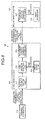
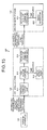
- FIG. 6 is a diagram of an example of a process of the communication system according to the second embodiment.
- the terminal apparatus 110 while the terminal apparatus 110 is communicating with the first base station 120, the first base station 120 is selected as the downlink base station at step S502 in FIG. 5 and the second base station 130 is selected as the uplink base station at step S505.
- the terminal apparatus 110 transmits an asymmetric transmission request (request signal) to the first base station 120 at step S507 in FIG. 5 .
- the asymmetric transmission request transmitted by the terminal apparatus 110 includes correspondence information that indicates the base station that corresponds to the uplink and the base station that corresponds to the downlink in the asymmetric transmission.
- the first base station 120 includes a terminal communication unit 611, a time division controller 612, a radio scheduler 613, and an inter-base station communication unit 614.
- the terminal communication unit 611 receives and outputs to the time division controller 612, the asymmetric transmission request transmitted from the terminal apparatus 110.
- the time division controller 612 based on the correspondence information included in the asymmetric transmission request output from the terminal communication unit 611, allocates time resources for the uplink and the downlink.
- the time division controller 612 allocates the odd numbered wireless frames “1", “3”, “5", “7”, and “9” to the uplink and allocates the even numbered wireless frames "0", “2", “4", “6” , and “8” to the downlink (see FIG. 4 ).
- the time division controller 612 notifies the radio scheduler 613 of the wireless resources allocated to the downlink.
- the time division controller 612 notifies the second base station 130 of the asymmetric transmission request, via the inter-base station communication unit 614.
- the asymmetric transmission request transmitted by the time division controller 612 includes link direction information that indicates that the second base station 130 corresponds to the uplink and information indicating the time resources allocated to the uplink.
- the radio scheduler 613 performs downlink scheduling from the first base station 120 to the terminal apparatus 110, using the time resources indicated by the time division controller 612. Based on the scheduling result from the radio scheduler 613, the first base station 120 performs downlink communication with the terminal apparatus 110.
- the second base station 130 includes an inter-base station communication unit 621, and a radio scheduler 622.
- the inter-base station communication unit 62 receives the asymmetric transmission request transmitted from the first base station 120.
- the inter-base station communication unit 621 notifies the radio scheduler 622 of the link direction and the time resources included in the received asymmetric transmission request.
- the radio scheduler 622 performs uplink scheduling from the terminal apparatus 110 to the second base station 130, using the time resources indicated by the inter-base station communication unit 621.
- the second base station 130 based on the scheduling result from the radio scheduler 622, performs uplink communication with the terminal apparatus 110.
- Transmission of the asymmetric transmission request between the terminal apparatus 110 and the first base station 120 is performed through respective wireless communication interfaces. Further, the transmission of the asymmetric transmission request between the first base station 120 and the second base station 130 is performed through respective communication interfaces and, for example, is implemented by wired communication.
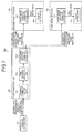
- FIG. 7 is a diagram of a modified example of a process of the communication system depicted in FIG. 6 .
- the communication system 100 includes the terminal apparatus 110, the first base station 120, the second base station 130, and a third base station 710. Further, while the terminal apparatus 110 is communicating with the first base station 120, the second base station 130 is selected as the uplink base station at step S502 in FIG. 5 and the third base station 710 is selected as the downlink base station at step S505.
- the terminal apparatus 110 transmits an asymmetric transmission request to the first base station 120 at step S507 in FIG. 5 .
- the time division controller 612 transmits the asymmetric transmission request, via the inter-base station communication unit 614, to the second base station 130 and the third base station 710.
- the asymmetric transmission request provided to the second base station 130 includes link direction information indicating that the second base station 130 corresponds to the uplink and information indicating the time resources allocated to the uplink.
- the asymmetric transmission request provided to the third base station 710 includes link direction information indicating that the third base station 710 corresponds to the downlink and information indicating the time resources allocated for the downlink.
- the third base station 710 includes an inter-base station communication unit 711 and a radio scheduler 712.
- the inter-base station communication unit 711 receives the asymmetric transmission request transmitted from the first base station 120.
- the inter-base station communication unit 711 notifies the radio scheduler 712 of the link direction and the time resources included in the received asymmetric transmission request.
- the radio scheduler 712 performs downlink scheduling from the third base station 710 to the terminal apparatus 110, using the time resources indicated by the inter-base station communication unit 711.
- the third base station 710 based on the scheduling result from the radio scheduler 712, performs downlink communication with the terminal apparatus 110.
- the base station that has received the asymmetric transmission request from the terminal apparatus 110 may be a base station that does not correspond to the uplink and the downlink.
- uplink communication and downlink communication are mutually performed by time division. Consequently, communication that is in the same direction, but with different base stations can be prevented.
- the effects of the communication system 100 according to the first embodiment can be achieved and communication circuit of the terminal apparatus 110 can be simplified, enabling reductions in the manufacturing cost and power consumption of the terminal apparatus 110. Further, since the simultaneous transmission of signals to different base stations can be prevented, transmission strength of the signals can be assured, enabling communication quality to be improved.
- FIG. 8 is a diagram of an example of operation of the communication system according to a third embodiment.
- the first base station 120 includes a traffic meter 810 in addition to the configuration depicted in FIG. 6 .
- the traffic meter 810 measures the uplink traffic at the terminal apparatus 110 and the downlink traffic at the terminal apparatus 110. For example, the traffic meter 810 acquires downlink request information transmitted by the terminal apparatus 110 to the first base station 120 and uplink request information transmitted by the terminal apparatus 110 to the second base station 130 and based on the acquired request information, measures the uplink and downlink traffic, respectively.
- the traffic meter 810 notifies the time division controller 612 of the measured uplink and downlink traffic.
- the notification of the uplink and downlink traffic from the traffic meter 810 to the time division controller 612 may be performed periodically, or may be performed when the first base station 120 receives an asymmetric transmission request from the terminal apparatus 110.
- the time division controller 612 calculates the ratio of uplink data rate at the terminal apparatus 110 and the downlink data rate at the terminal apparatus 110.
- the time division controller 612 allocates time resources to the uplink and the downlink of the terminal apparatus 110 to become as close as possible to the calculated ratio of the data rates.
- the time division controller 612 performs allocation for a 3:1 ratio of the downlink data rate to the uplink data rate. In this case, the time division controller 612 performs allocations such that the time resources allocated to the downlink and the time resources allocated to the uplink are at a ratio of 3:1 (see, for example, FIG. 9 ).
- FIG. 9 is a diagram of time resource allocation according to the third embodiment.
- the traffic measured by the traffic meter 810 is assumed to be 384 [kbps] for the downlink data rate and 128 [kbps] for the uplink data rate, giving a downlink to uplink ratio of 3:1.
- the time division controller 612 for example, allocates wireless frames “0”, “2”, “3”, “4", “6”, “7”, and “8” to the downlink channel 410. Further, the time division controller 612 allocates wireless frames “1”, “5", and “9” to the uplink channel 420.
- time resources allocated to the downlink and the time resources allocated to the uplink have a ratio of approximately 3:1.
- time resource allocation to the downlink and the uplink can be changed according to the amount of uplink and downlink traffic.
- time resources can be allocated to the uplink and the downlink of the terminal apparatus 110, based on the uplink data traffic and the downlink data traffic. Consequently, time resources can be efficiently allocated to the uplink and the downlink. For example, during data transmission, the amount of uplink traffic and downlink traffic differ greatly. Therefore, by allocating time resources according to the amount of uplink data and downlink data traffic, time resources can be efficiently used.
- FIG. 10 is a diagram of an example of operation of the communication system according to a fourth embodiment.
- the terminal apparatus 110 according to the fourth embodiment includes an interference power measurer 1011.
- the second base station 130 according to the fourth embodiment includes an interference power measurer 1012 in addition to the configuration depicted in FIG. 6 .
- the interference power measurer 1011 of the terminal apparatus 110 measures the downlink interference power from the first base station 120 to the terminal apparatus 110, for each wireless frame into which the wireless resources are time divided. For example, the interference power measurer 1011 measures interference power, based on a signal (e.g., a pilot signal) transmitted from the first base station 120. The interference power measurer 1011 notifies the first base station 120 of the measured interference power.
- a signal e.g., a pilot signal
- the interference power measurer 1012 of the second base station 130 measures the uplink interference power from the terminal apparatus 110 to the second base station 130, for each wireless frame into which the wireless resources are divided. For example, the interference power measurer 1012 measures the interference power, based on a signal (e.g., a pilot signal) transmitted from the terminal apparatus 110. The interference power measurer 1012 notifies the first base station 120 of the measured interference power.
- a signal e.g., a pilot signal
- Notification of the interference power from the interference power measurer 1011 to the first base station 120 may be performed periodically, or may be performed when the terminal apparatus 110 transmits an asymmetric transmission request to the first base station 120. Further, the notification of the interference power from the interference power measurer 1012 to the first base station 120 may be performed periodically, or may be performed when the interference power measurer 1012 receives an asymmetric transmission request from the first base station 120.
- the time division controller 612 of the first base station 120 allocates time resources to the uplink and the downlink respectively, based in the downlink interference power indicated by the terminal apparatus 110 and the uplink interference power indicated by the second base station 130.
- the time division controller 612 preferentially allocates to the downlink, wireless frames having a low downlink interference power. Further, based on the uplink interference power indicated for each wireless frame by the second base station 130, the time division controller 612 preferentially allocates to the uplink, wireless frames having a low uplink interference power.
- Notification of the interference power between the terminal apparatus 110 and the first base station 120 is performed through respective wireless communication interfaces. Further, the notification of the interference power between the first base station 120 and the second base station 130 is performed through respective communication interfaces and, for example, is implemented by wired communication.
- FIG. 11 is a diagram of an example of time resource allocation according to the fourth embodiment.
- An interference power curve 1110 indicates the average downlink interference power from the first base station 120 to the terminal apparatus 110, for each wireless frame. This average, for example, is calculated at constant intervals.
- the interference power curve 1110 is relatively small at wireless frames "0", “1", “4", “5", “8", and “9” and relatively large at wireless frames "2", "3", “6", and "7".
- An interference power curve 1120 indicates the average uplink interference power from the terminal apparatus 110 to the second base station 130, for each wireless frame. This average, for example, is calculated at constant intervals.
- the interference power curve 1120 is relatively large at wireless frames “0", “1", "4", "5", "8", and "9” and is relatively small at wireless frames “2", "3", "6", and "7".
- the time division controller 612 allocates to the downlink from the first base station 120 to the terminal apparatus 110, wireless frames “0”, “1”, “4", “5", “8”, and “9” for which the interference power curve 1110 is small. Further, the time division controller 612 allocates to the uplink from the terminal apparatus 110 to the second base station 130, wireless frames "2", “3”, “6", and “7” for which the interference power curve 1120 is relatively small. In this manner, the time division controller 612, based on the measured interference power, automatically allocates time resources such that the interference power becomes small.
- time resources are allocated to the uplink and the downlink of the terminal apparatus 110, based on the interference power of uplink data and downlink data. Consequently, since time resources having low interference power can be preferentially allocated to the uplink and the downlink, communication quality can be improved.
- a portion of the control channel may be transmitted and received by a base station that is not the optimal base station.
- the first base station 120 is the optimal base station for the downlink at the terminal apparatus 110
- the downlink control information 153 is transmitted from the second base station 130 to the terminal apparatus 110.
- the second base station 130 is the optimal base station for the uplink at the terminal apparatus 110
- the uplink control information 143 is transmitted from the terminal apparatus 110 to the first base station 120.
- the downlink control information 153 and the uplink control information 143 are transmitted to base stations that are not the optimal base stations and consequently, compared to transmission to the optimal base stations, transmission strength becomes strong. As a result, interference between the first base station 120 and the second base station 130 consequent to the downlink control information 153 and the uplink control information 143 may occur. In particular, when the transmission strength of the uplink control information 143 becomes great, interference of communication to the second base station 130 may increase, causing communication quality to deteriorate.
- FIG. 12 is a diagram of a process of the communication system according to the fifth embodiment.
- the radio scheduler 613 of the first base station 120 notifies the second base station 130 of the wireless resources allocated to the uplink control channel of the downlink at the terminal apparatus 110 (uplink control channel resource information).
- the radio scheduler 622 of the second base station 130 allocates for each communication of the second base station 130, wireless resources that are different from the wireless resources indicated by the radio scheduler 613 of the first base station 120. For example, the radio scheduler 622 prohibits subsequent use of the wireless resources indicated by the radio scheduler 613. Further, if the wireless resources indicated by the radio scheduler 613 have already been allocated, the radio scheduler 622 performs reallocation of other available time resources.
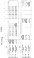
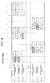
- FIG. 13 is a diagram of an example of time resource allocation according to the fifth embodiment.
- components identical to those depicted in FIG. 4 are given the same reference numerals used in FIG. 4 and description thereof is omitted.
- the horizontal axis represents wireless frames (time resources).
- the vertical axis in FIG. 13 represents frequency resources.
- Downlink resources 1310 represent wireless resources allocated to the downlink of the terminal apparatus 110.
- the downlink resources 1310 include control channel resources 1311 and data channel resources 1312.
- a wireless resource 1311a among the control channel resources 1311 is a wireless resource allocated to the uplink control channel of the downlink of the terminal apparatus 110.
- Uplink resources 1320 represent wireless resources allocated to the uplink of the terminal apparatus 110.
- the uplink resources 1320 include control channel resources 1321 and data channel resources 1322.
- a wireless resource 1321a among the control channel resources 1321 is the same wireless resource (the wireless resource 1311a) of the control channel resources 1311.
- the radio scheduler 613 of the first base station 120 notifies the second base station 130 of the wireless resource 1321a allocated to the uplink control channel of the downlink of the terminal apparatus 110.
- the radio scheduler 622 of the second base station 130 based on the notification from the radio scheduler 613 of the first base station 120, allocates to each communication of the second base station 130, a wireless resource that is different from the wireless resource 1321a.
- the first base station 120 notifies the second base station 130 of the wireless resources allocated for the control information that is received from the terminal apparatus 110 and for downlink data transmission.
- the second base station 130 allocates to each communication at the second base station 130, a wireless resource that is different from the time resource notified by the first base station 120.
- interference of communication to the second base station 130 consequent to increased transmission strength of the control information can be prevented.
- the second base station 130 may notify the first base station 120 of the wireless resources allocated for the control information that is received from the terminal apparatus 110 and for uplink data reception.
- the first base station 120 allocates to each communication at the first base station 120, a wireless resource that is different from the time resource notified by the second base station 130. Consequently, interference of communication to the first base station 120 consequent to increased transmission strength of the control information can be prevented.
- FIG. 14 is a diagram of an example of timing overlap of the uplink and the downlink. Even when different wireless frames are allocated for the uplink and the downlink, if the timing of the downlink communication and the uplink communication deviate, the uplink and downlink communication may temporally overlap.
- the uplink and downlink communication overlap.
- either the downlink communication or the uplink communication is unable to be performed.
- FIG. 15 is a diagram of an example of a process of the communication system according to the sixth embodiment.
- the terminal apparatus 110 based on the pilot signal periodically transmitted from the first base station 120, measures the communication timing at the first base station 120. Further, the terminal apparatus 110, based on the pilot signal periodically transmitted from the second base station 130, measures the communication timing at the second base station 130.
- the terminal apparatus 110 transmits to the first base station 120, an asymmetric transmission request that includes information indicating the communication timings measured for the first base station 120 and the second base station 130, respectively.
- the time division controller 612 based on the information included in the asymmetric transmission request and indicating the communication timings for the first base station 120 and the second base station 130, respectively, allocates time resources to the uplink and the downlink. For example, the time division controller 612 allocates the time resources to have a guard time that is based on each of the communication timings, such that the communication timing of the downlink by the first base station 120 and the uplink by the second base station 130 do not overlap.
- FIG. 16 is a diagram of an example of a time resource allocation process according to the sixth embodiment.
- components identical to those depicted in FIG. 4 are given the same reference numerals used in FIG.4 and description thereof is omitted.
- wireless frames "0", “1” , “4", “5", “8” , and “9” are allocated to the downlink channel 410.
- wireless frames "2", “3", “6", and “7” are allocated to the uplink channel 420.
- the time division controller 612 of the first base station 120 allocates the time resources to have a guard time that is based on each of the communication timings, such that the communication timing of the downlink by the first base station 120 and the uplink by the second base station 130 do not overlap.
- the communication timing of the downlink and the uplink do not overlap by allocating to the downlink, time resources that are sufficiently long.
- the terminal apparatus 110 measures the communication timing of the first base station 120 and the communication timing of the second base station 130.
- the first base station 120 and the second base station 130 allocate to the uplink and the downlink, time resources to have a guard time that is based on the respective timings measured by the terminal apparatus 110.
- a guard time is set so that the uplink and the downlink do not temporally overlap, enabling improvement of the communication quality.
- first base station 120 and the second base station 130 are different base stations.
- first base station 120 and the second base station 130 for example, mutually perform communication through a backbone network.
- a configuration may be such that the first base station 120 and the second base station 130 are included the same base station.
- FIG. 17 is a diagram of a modified example of the communication system according to FIG. 1 .
- the communication system 100 includes a base station control apparatus 1710 in addition to the configuration depicted in FIG. 1 .
- the first base station 120 and the second base station 130 are connected to the base station control apparatus 1710 through a dedicated line.
- the base station control apparatus 1710 performs communication by controlling the first base station 120 and the second base station 130.
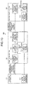
- FIG. 18 is a diagram of an example of a process of the base station depicted in FIG. 17 .
- a base station 1800 depicted in FIG. 18 is a base station that includes the first base station 120, the second base station 130, and the base station control apparatus 1710 depicted in FIG. 17 .
- the base station 1800 includes a terminal communication unit 1811, a time division controller 1812, a radio scheduler 1813, and a radio scheduler 1814.
- the terminal communication unit 1811 has a configuration that corresponds to the terminal communication unit 611 depicted in FIG. 6 .
- the terminal communication unit 1811 is implemented by the first base station 120 and the second base station 130, receives the asymmetric transmission request transmitted from the terminal apparatus 110, and outputs the received the asymmetric transmission request to the time division controller 1812.
- the time division controller 1812 has a configuration that corresponds to the time division controller 612 depicted in FIG. 6 .
- the time division controller 1812 based on correspondence information included in the asymmetric transmission request output from the terminal communication unit 1811, allocates time resources to the uplink and the downlink.
- the time division controller 1812 notifies the radio scheduler 1813 of the time resources allocated to the downlink.
- the time division controller 1812 further notifies the radio scheduler 1814 of the time resources allocated to the downlink.
- the radio scheduler 1813 has a configuration that corresponds to the radio scheduler 613 depicted in FIG. 6 .
- the radio scheduler 1813 by the time resources indicated by the time division controller 1812, performs scheduling of the downlink from the first base station 120 to the terminal apparatus 110.
- the base station 1800 performs downlink communication with the terminal apparatus 110, based on the scheduling results from the radio scheduler 1813.
- the radio scheduler 1814 has a configuration that corresponds to the radio scheduler 622 depicted in FIG. 6 .
- the radio scheduler 1814 by the time resources indicated by the time division controller 1812, performs scheduling of the uplink from the terminal apparatus 110 to the second base station 130.
- the base station 1800 performs uplink communication with the terminal apparatus 110, based on the scheduling result from the radio scheduler 1814.
Landscapes
- Engineering & Computer Science (AREA)
- Computer Networks & Wireless Communication (AREA)
- Signal Processing (AREA)
- Mobile Radio Communication Systems (AREA)
Applications Claiming Priority (1)
| Application Number | Priority Date | Filing Date | Title |
|---|---|---|---|
| PCT/JP2009/062998 WO2011007451A1 (ja) | 2009-07-17 | 2009-07-17 | 端末装置、通信システムおよび通信方法 |
Publications (2)
| Publication Number | Publication Date |
|---|---|
| EP2456272A1 true EP2456272A1 (de) | 2012-05-23 |
| EP2456272A4 EP2456272A4 (de) | 2017-06-28 |
Family
ID=43449066
Family Applications (1)
| Application Number | Title | Priority Date | Filing Date |
|---|---|---|---|
| EP09847349.9A Withdrawn EP2456272A4 (de) | 2009-07-17 | 2009-07-17 | Endgerät, kommunikationssystem und kommunikationsverfahren |
Country Status (6)
| Country | Link |
|---|---|
| US (1) | US9730190B2 (de) |
| EP (1) | EP2456272A4 (de) |
| JP (1) | JP5488601B2 (de) |
| KR (1) | KR101383513B1 (de) |
| CN (1) | CN102474851B (de) |
| WO (1) | WO2011007451A1 (de) |
Families Citing this family (15)
| Publication number | Priority date | Publication date | Assignee | Title |
|---|---|---|---|---|
| US9232462B2 (en) * | 2009-10-15 | 2016-01-05 | Qualcomm Incorporated | Methods and apparatus for cross-cell coordination and signaling |
| US9398592B2 (en) * | 2011-08-03 | 2016-07-19 | Telefonaktiebolaget Lm Ericsson (Publ) | Scheduling apparatus and method for a TDD communication system |
| JP2013175893A (ja) * | 2012-02-24 | 2013-09-05 | Kddi Corp | 制御チャネル無線リソース割当装置、及び制御チャネル無線リソース割当プログラム |
| JP6050028B2 (ja) * | 2012-05-25 | 2016-12-21 | シャープ株式会社 | 端末、基地局、通信方法及び集積回路 |
| US9185587B2 (en) | 2012-10-18 | 2015-11-10 | Apple Inc. | Load estimation in 3GPP networks |
| US8958799B2 (en) * | 2012-10-18 | 2015-02-17 | Apple Inc. | Wireless device based inter radio access technology handover initiation |
| CN103959875A (zh) * | 2012-10-19 | 2014-07-30 | 华为技术有限公司 | 通信方法和设备 |
| ES2663022T3 (es) | 2013-02-01 | 2018-04-10 | Huawei Technologies Co., Ltd. | Método y dispositivo de interacción de datos |
| EP2958355B1 (de) * | 2013-02-15 | 2017-12-20 | Mitsubishi Electric Corporation | Kommunikationssystem |
| US9590792B2 (en) * | 2013-04-01 | 2017-03-07 | Marvell World Trade Ltd. | Termination of wireless communication uplink periods to facilitate reception of other wireless communications |
| CN104737604B9 (zh) * | 2013-06-28 | 2018-12-07 | 华为技术有限公司 | 上行数据的传输方法、无线通信节点和终端 |
| US9319957B1 (en) * | 2013-07-31 | 2016-04-19 | Sprint Spectrum L.P. | Dynamic swapping of uplink and downlink base stations |
| US9608678B1 (en) | 2013-12-19 | 2017-03-28 | Marvell International Ltd. | Method and apparatus for mitigating interference between wireless local area network (WLAN) communications and cellular communications |
| JP6254467B2 (ja) * | 2014-03-20 | 2017-12-27 | Kddi株式会社 | 端末装置、基地局装置、使用アーキテクチャ決定方法、及びコンピュータプログラム |
| EP3316635B1 (de) | 2015-06-24 | 2021-08-25 | NTT DoCoMo, Inc. | Benutzervorrichtung, basisstation und kommunikationsverfahren zur nutzung vorbestimmter uplink funkressourcen |
Family Cites Families (32)
| Publication number | Priority date | Publication date | Assignee | Title |
|---|---|---|---|---|
| US5548806A (en) | 1993-01-25 | 1996-08-20 | Kokusai Denshin Denwa Co., Ltd. | Mobile communication system having a cell structure constituted by integrating macro cells and micro cells |
| JP2669288B2 (ja) | 1993-01-25 | 1997-10-27 | 国際電信電話株式会社 | マイクロセル/マクロセル統合移動通信方式 |
| JPH0730527A (ja) * | 1993-06-25 | 1995-01-31 | Matsushita Electric Ind Co Ltd | 無線パケット伝送装置 |
| JP3392710B2 (ja) * | 1997-06-04 | 2003-03-31 | 株式会社東芝 | 無線通信システム |
| JP3310209B2 (ja) * | 1998-01-28 | 2002-08-05 | 株式会社エヌ・ティ・ティ・ドコモ | 通信チャネル選択方法および基地局装置 |
| FI107218B (fi) * | 1998-10-15 | 2001-06-15 | Nokia Networks Oy | Menetelmä kanavan allokoimiseksi matkaviestinjärjestelmässä |
| JP2001339770A (ja) | 2000-05-30 | 2001-12-07 | Matsushita Electric Ind Co Ltd | 無線通信システム及びそれに用いる通信端末装置 |
| JP2002112326A (ja) * | 2000-10-02 | 2002-04-12 | Ntt Docomo Inc | 無線リソース割当方法及び基地局装置 |
| JP3816334B2 (ja) * | 2000-12-22 | 2006-08-30 | 株式会社エヌ・ティ・ティ・ドコモ | 無線リソース割当方法及び基地局 |
| JP2002204470A (ja) * | 2000-12-28 | 2002-07-19 | Mitsubishi Electric Corp | 無線通信システム、無線通信システムの通信制御方法及びその管理方法 |
| JP3634797B2 (ja) * | 2001-11-30 | 2005-03-30 | 株式会社東芝 | 無線リンク制御方法および通信システムおよび通信装置 |
| US7463616B1 (en) * | 2002-03-28 | 2008-12-09 | Nortel Networks Limited | Scheduling based on channel change indicia |
| US7133673B2 (en) * | 2002-06-28 | 2006-11-07 | Interdigital Technology Corporation | Method and system for determining correct escape mechanisms and controlling interference in third generation wireless systems |
| JP3898681B2 (ja) * | 2003-09-30 | 2007-03-28 | 株式会社東芝 | 携帯端末、通信システムおよび通信方法 |
| US7142861B2 (en) | 2003-12-12 | 2006-11-28 | Telefonaktiebolaget Lm Ericsson (Publ) | Mobile communications in a hierarchical cell structure |
| JP2006054597A (ja) | 2004-08-10 | 2006-02-23 | Ntt Docomo Inc | スロット割当装置及びその方法 |
| JP4592545B2 (ja) * | 2005-08-24 | 2010-12-01 | 株式会社エヌ・ティ・ティ・ドコモ | 送信電力制御方法及び移動通信システム |
| US8694042B2 (en) * | 2005-10-14 | 2014-04-08 | Qualcomm Incorporated | Method and apparatus for determining a base station's transmission power budget |
| KR101202901B1 (ko) | 2005-11-05 | 2012-11-19 | 인하대학교 산학협력단 | 무선 인지 기술을 기반으로 하는 무선통신시스템에서 자원 분배방법 및 이를 지원하는 시스템 |
| JP4430052B2 (ja) | 2006-06-19 | 2010-03-10 | 株式会社エヌ・ティ・ティ・ドコモ | 移動通信システム、ユーザ装置及び送信方法 |
| JP4676533B2 (ja) * | 2006-07-14 | 2011-04-27 | 富士通株式会社 | 移動通信システム及び基地局 |
| JP4703513B2 (ja) | 2006-08-22 | 2011-06-15 | 株式会社エヌ・ティ・ティ・ドコモ | 移動通信システムで使用される無線基地局及び方法 |
| KR20080034290A (ko) * | 2006-10-16 | 2008-04-21 | 삼성전자주식회사 | 휴대 인터넷 서비스 시스템 및 방법 |
| JP4485547B2 (ja) * | 2007-06-21 | 2010-06-23 | 株式会社エヌ・ティ・ティ・ドコモ | 移動局、および、移動局における送信電力制御方法 |
| US20090161627A1 (en) * | 2007-12-19 | 2009-06-25 | Freescale Semiconductor, Inc. | Switching communication networks in a mobile device |
| JP5174520B2 (ja) * | 2008-04-18 | 2013-04-03 | 京セラ株式会社 | 移動通信システム、およびチャネル割り当て方法 |
| JP4352281B1 (ja) * | 2008-05-23 | 2009-10-28 | 日本電気株式会社 | 無線通信システム、基地局、基地局間同期方法、プログラム |
| JP5173667B2 (ja) * | 2008-08-11 | 2013-04-03 | 株式会社エヌ・ティ・ティ・ドコモ | ユーザ装置、無線基地局及び方法 |
| US8149813B2 (en) * | 2008-08-13 | 2012-04-03 | Research In Motion Limited | Wireless device having fast-receive mode for measuring received signal strength (RSSI) for higher time division multiple access (TDMA) multislot classes |
| US8391244B2 (en) * | 2008-08-14 | 2013-03-05 | Intel Mobile Communications GmbH | Radio communication terminal devices, radio communication network system, method for operating a radio communication terminal device |
| KR101540815B1 (ko) * | 2008-09-24 | 2015-08-07 | 엘지전자 주식회사 | 무선통신 시스템에서의 상향링크와 하향링크를 위한 무선자원의 관리 방법 |
| US9001783B2 (en) * | 2009-01-05 | 2015-04-07 | Intel Corporation | Dual base stations for wireless communications systems |
-
2009
- 2009-07-17 JP JP2011522673A patent/JP5488601B2/ja not_active Expired - Fee Related
- 2009-07-17 CN CN200980160456.1A patent/CN102474851B/zh not_active Expired - Fee Related
- 2009-07-17 EP EP09847349.9A patent/EP2456272A4/de not_active Withdrawn
- 2009-07-17 KR KR1020127000407A patent/KR101383513B1/ko not_active Expired - Fee Related
- 2009-07-17 WO PCT/JP2009/062998 patent/WO2011007451A1/ja not_active Ceased
-
2011
- 2011-12-30 US US13/341,083 patent/US9730190B2/en not_active Expired - Fee Related
Non-Patent Citations (1)
| Title |
|---|
| See references of WO2011007451A1 * |
Also Published As
| Publication number | Publication date |
|---|---|
| CN102474851A (zh) | 2012-05-23 |
| CN102474851B (zh) | 2016-04-13 |
| US9730190B2 (en) | 2017-08-08 |
| JP5488601B2 (ja) | 2014-05-14 |
| KR20120025590A (ko) | 2012-03-15 |
| EP2456272A4 (de) | 2017-06-28 |
| US20120099458A1 (en) | 2012-04-26 |
| WO2011007451A1 (ja) | 2011-01-20 |
| JPWO2011007451A1 (ja) | 2012-12-20 |
| KR101383513B1 (ko) | 2014-04-08 |
Similar Documents
| Publication | Publication Date | Title |
|---|---|---|
| EP2456272A1 (de) | Endgerät, kommunikationssystem und kommunikationsverfahren | |
| JP4982409B2 (ja) | 無線通信装置及び方法 | |
| US7944879B2 (en) | Resource allocating apparatus and method in multihop relay wireless communication system | |
| US8467730B2 (en) | Radio communication method, base station apparatus and terminal apparatus in radio communication system, and radio communication system | |
| EP4097929B1 (de) | Kommunikationssteuerungsmechanismus mit vollduplex-kommunikationsverbindung | |
| US20150103789A1 (en) | Radio communication system, radio base station apparatus, terminal apparatus, and radio resource allocation method | |
| JP2003032734A (ja) | 移動通信システムにおけるタイムスロット割当て方法、信号伝送方法、無線基地局制御装置、無線基地局及び移動局 | |
| US8345582B2 (en) | Mobile communications system, base station apparatus, user apparatus and method | |
| CN103139784B (zh) | 用户设备收发转化时间的处理方法及装置 | |
| EP3273730A1 (de) | Benutzervorrichtung und basisstation | |
| EP3155845B1 (de) | Netzwerkvorrichtung und verfahren zur zuordnung einer radiofrequenzband an einer benutzervorrichtung | |
| JP2016508306A (ja) | ネットワーク支援型d2dのための物理チャネル設計 | |
| CN101895987B (zh) | 回程链路上行资源配置指示及数据传输的方法及系统 | |
| KR20140135331A (ko) | 무선 통신 시스템에서 동적 시분할 복식 시스템 운영 방법 및 장치 | |
| US20100080194A1 (en) | Radio base station and mobile station | |
| CN105122917A (zh) | 动态tdd配置系统方法 | |
| AU2014266127A1 (en) | Interference measurement method and apparatus for controlling inter-cell interference in wireless communication system | |
| JPWO2010150898A1 (ja) | 無線通信システム、無線基地局及び無線通信方法 | |
| KR20120127490A (ko) | 무선 통신 시스템, 통신 제어 방법, 및 기지국 및 이동 단말기 | |
| US20260122673A1 (en) | Methods and apparatus of channel occupancy time (cot) sharing in sidelink unlicensed communication systems | |
| CN106792776B (zh) | 一种波束处理方法和基站 | |
| CN101557594A (zh) | 一种多载波功率共享的方法、装置及系统 | |
| CN101442357A (zh) | 一种采用支持Relay的帧结构进行无线传输的方法和系统 |
Legal Events
| Date | Code | Title | Description |
|---|---|---|---|
| PUAI | Public reference made under article 153(3) epc to a published international application that has entered the european phase |
Free format text: ORIGINAL CODE: 0009012 |
|
| 17P | Request for examination filed |
Effective date: 20120213 |
|
| AK | Designated contracting states |
Kind code of ref document: A1 Designated state(s): AT BE BG CH CY CZ DE DK EE ES FI FR GB GR HR HU IE IS IT LI LT LU LV MC MK MT NL NO PL PT RO SE SI SK SM TR |
|
| DAX | Request for extension of the european patent (deleted) | ||
| RA4 | Supplementary search report drawn up and despatched (corrected) |
Effective date: 20170526 |
|
| RIC1 | Information provided on ipc code assigned before grant |
Ipc: H04W 72/12 20090101ALI20170519BHEP Ipc: H04W 88/02 20090101ALN20170519BHEP Ipc: H04W 72/04 20090101AFI20170519BHEP |
|
| GRAP | Despatch of communication of intention to grant a patent |
Free format text: ORIGINAL CODE: EPIDOSNIGR1 |
|
| RIC1 | Information provided on ipc code assigned before grant |
Ipc: H04W 72/04 20090101AFI20180911BHEP Ipc: H04W 72/12 20090101ALI20180911BHEP Ipc: H04W 88/02 20090101ALN20180911BHEP |
|
| INTG | Intention to grant announced |
Effective date: 20180926 |
|
| STAA | Information on the status of an ep patent application or granted ep patent |
Free format text: STATUS: THE APPLICATION IS DEEMED TO BE WITHDRAWN |
|
| 18D | Application deemed to be withdrawn |
Effective date: 20190207 |