EP2456667B1 - Structure pour cabine d'un vehicule - Google Patents
Structure pour cabine d'un vehicule Download PDFInfo
- Publication number
- EP2456667B1 EP2456667B1 EP10735287.4A EP10735287A EP2456667B1 EP 2456667 B1 EP2456667 B1 EP 2456667B1 EP 10735287 A EP10735287 A EP 10735287A EP 2456667 B1 EP2456667 B1 EP 2456667B1
- Authority
- EP
- European Patent Office
- Prior art keywords
- housing part
- monument
- floor
- housing
- cabin
- Prior art date
- Legal status (The legal status is an assumption and is not a legal conclusion. Google has not performed a legal analysis and makes no representation as to the accuracy of the status listed.)
- Not-in-force
Links
- 238000009434 installation Methods 0.000 claims description 8
- 230000003213 activating effect Effects 0.000 claims 1
- 238000005253 cladding Methods 0.000 description 17
- 238000011161 development Methods 0.000 description 11
- 230000018109 developmental process Effects 0.000 description 11
- 238000006073 displacement reaction Methods 0.000 description 5
- 239000000463 material Substances 0.000 description 3
- 239000002131 composite material Substances 0.000 description 2
- 238000009408 flooring Methods 0.000 description 2
- 238000003780 insertion Methods 0.000 description 2
- 230000037431 insertion Effects 0.000 description 2
- 239000007788 liquid Substances 0.000 description 2
- 230000007246 mechanism Effects 0.000 description 2
- 229920002430 Fibre-reinforced plastic Polymers 0.000 description 1
- 238000010276 construction Methods 0.000 description 1
- 239000000356 contaminant Substances 0.000 description 1
- 230000001419 dependent effect Effects 0.000 description 1
- 238000013461 design Methods 0.000 description 1
- 238000000605 extraction Methods 0.000 description 1
- 230000002349 favourable effect Effects 0.000 description 1
- 239000000835 fiber Substances 0.000 description 1
- 239000011151 fibre-reinforced plastic Substances 0.000 description 1
- 230000001771 impaired effect Effects 0.000 description 1
- 238000012423 maintenance Methods 0.000 description 1
- 238000000034 method Methods 0.000 description 1
- 239000000203 mixture Substances 0.000 description 1
- 239000004033 plastic Substances 0.000 description 1
- 229920003023 plastic Polymers 0.000 description 1
- 238000005096 rolling process Methods 0.000 description 1
- 239000007787 solid Substances 0.000 description 1
- 239000011343 solid material Substances 0.000 description 1
- 239000002699 waste material Substances 0.000 description 1
Images




Classifications
-
- B—PERFORMING OPERATIONS; TRANSPORTING
- B64—AIRCRAFT; AVIATION; COSMONAUTICS
- B64D—EQUIPMENT FOR FITTING IN OR TO AIRCRAFT; FLIGHT SUITS; PARACHUTES; ARRANGEMENT OR MOUNTING OF POWER PLANTS OR PROPULSION TRANSMISSIONS IN AIRCRAFT
- B64D11/00—Passenger or crew accommodation; Flight-deck installations not otherwise provided for
- B64D11/02—Toilet fittings
-
- B—PERFORMING OPERATIONS; TRANSPORTING
- B64—AIRCRAFT; AVIATION; COSMONAUTICS
- B64D—EQUIPMENT FOR FITTING IN OR TO AIRCRAFT; FLIGHT SUITS; PARACHUTES; ARRANGEMENT OR MOUNTING OF POWER PLANTS OR PROPULSION TRANSMISSIONS IN AIRCRAFT
- B64D11/00—Passenger or crew accommodation; Flight-deck installations not otherwise provided for
- B64D2011/0046—Modular or preassembled units for creating cabin interior structures
Definitions
- the invention relates to a monument for a cabin of a vehicle, the use of a monument in a passenger cabin of a vehicle and a vehicle having a passenger cabin, at least one passenger cabin exit and at least one monument.
- Passenger cabins of modern vehicles are distinguished by the fact that they not only provide facilities for accommodating passengers, but also facilities that make the stay on board the vehicle pleasant.
- passenger cabins for example, of commercial aircraft usually different major installations, which are also known by the term "monument" and can fulfill a variety of different tasks.
- a monument could house a washroom with sanitary facilities that passengers can access and lock from the inside.
- monuments Due to the usually limited space available in vehicles monuments have a highly integrated structure and thus in a small space the greatest possible concentration of facilities, for example Sanitary articles, waste containers, paper towel dispensers, mirrors, lighting equipment and the like. Due to the strong space limitation, the prior art also discloses enlargeable monuments which have a variable housing design and extend, for example, in a stowed position only over a very small floor surface of a cabin floor, but in an operating position over a relatively large floor area, which extends as far as extends an area in front of a passenger cabin door.
- a sanitary installation is set forth, which achieves an enlargement of the floor plan in that a sanitary installation unit is rotatably mounted and can be pivoted from a stowed position to a plan-increasing position.
- a sanitary installation unit is rotatably mounted and can be pivoted from a stowed position to a plan-increasing position.
- a further object of the invention is to provide all the basic functions both in a reduced and in an enlarged plan in an enlargeable monument.
- the monument according to the invention has a first housing part with a bottom side and a connection side, a second housing part with a bottom side and a connection side and at least one first trim element.
- the first housing part is adapted to be fixed with its bottom side to a floor of the cabin.
- an outer cross section of the connecting side of one of the housing parts is dimensioned to be smaller than an opening cross section of the connecting side of the other housing part.
- the first housing part and the second housing part thus form a housing which limits the monument to the outside.
- the first housing part and / or the second housing part has locking means for locking the second housing part in a first relative position and in a second relative position to the first housing part.
- the first cladding element serves to create a gap between the connection side to disguise the first housing part and the second housing part in the second relative position.
- the monument according to the invention consists of two Operamonumenten, which are each realized by a housing part.
- a first housing part is to be firmly mounted on the floor of the passenger cabin of the vehicle.
- the second partial monument can be arranged in the form of the second housing part.
- the opening of the first housing part is accordingly designed so that the second housing part can be inserted into the opening of the first housing part.
- the opening cross-section of the second housing part may be designed such that the second housing part can be pushed over the first housing part.
- the monument according to the invention has a first cladding element with an arbitrary construction, which enables the first cladding means to cover the gap between the first housing part and the second housing part.
- a first cladding element with an arbitrary construction, which enables the first cladding means to cover the gap between the first housing part and the second housing part.
- solid materials such as plastics, fiber reinforced plastics or other composite materials, sandwich panels and the like conceivable.
- flexible materials by appropriate stretching, unwinding, unwinding or the like would also be suitable to be pulled over the gap to completely close the housing.
- a second cladding element could be provided, which complements the first cladding element.
- the second cladding element could be about be foldable, unrolled or extendable be arranged on the first cladding element, or on one of the housing parts.
- the monument according to the invention could be arranged in an area of the passenger cabin of the vehicle, in the immediate vicinity of which a passenger cabin door is arranged.
- a collapsed state i. when taking the first relative position
- the extension of the monument according to the invention ends in addition to the fully usable in this state passenger cabin door. If it is provided in an operating phase of the vehicle to keep the passenger cabin door closed, for example in the case of an aircraft during flight, the monument according to the invention can be pushed apart, with the second housing part then assuming the second relative position.
- the extension of the entire housing of the monument according to the invention then ends, for example, in an area which covers the passenger cabin door at least partially.
- an access opening is provided, which is preferably arranged parallel to an extension axis of the monument according to the invention.
- the extension axis is to be understood as the axis in which the relative movement of the two housing parts takes place relative to each other.
- the access opening arranged parallel to this extension axis permits a movement on the floor of the passenger cabin perpendicular to the extension direction into the monument according to the invention.
- Such an opening is at both reduced floor plan with the second housing part in the first relative position and in an enlarged plan with the second housing part in the first relative position usable.
- the first housing part and the second housing part are each configured such that the access opening remains completely free in each of the two relative positions.
- the second housing part has a cutout which, in the first relative position when the monument is pushed together, is aligned with an access opening arranged in the first housing part or vice versa.
- the gap between the two housing parts is formed by this cutout, which then has to be covered by the first cladding element.
- the extension direction of the monument according to the invention is advantageously aligned parallel to a wall of the cabin, so that from before or behind the monument of the invention arranged seats direct insight into an open access opening or on a person walking through the access opening person is not possible.
- the second housing part is movably mounted on a guide device relative to the first housing part.
- a guide device that allow easy sliding of the second housing part, so that the second housing part can be easily moved by a single person.
- the guide and support of the second housing part could be ensured by a guide means located on the cabin floor as well as by a arranged between the first housing part and the second housing part guide means in the manner of a drawer extension.
- the locking means is adapted to the first housing part and the second housing part if necessary rigidly connect with each other.
- the two housing parts are connected to one another at their top sides and / or bottom sides and / or side surfaces via corresponding mechanisms known in the prior art by means of corresponding actuating devices such that they can no longer be moved relative to one another.
- a guide device is provided for guiding the second housing part between the first housing part and the second housing part, the locking of the second housing part can also be effected by clamping or locking the guide device.
- the second housing part could be connected in an advantageous embodiment of the monument according to the invention, if necessary, with the cabin floor and / or with a cabin ceiling, so that locking of the second housing part can be independent of the first housing part.
- the locking means for locking the second housing part in all spatial directions at least one actuator.
- This could serve, for example, for introducing at least one latch body into at least one corresponding latch body receptacle in the cabin floor and / or in the cabin ceiling and / or in the first housing part.
- the locking body could thereby be moved transversely to the direction of extent of the monument according to the invention or to the direction of displacement of the second housing part in the respective locking body receptacle.
- a particularly easy lockability of the second housing part is made possible relative to the first housing part fixed thereto.
- the locking body is locked when it reaches its end position.
- this actuating device is a displaceable, rotatable, pushable or withdrawable Handle that moves the appropriate bar body via suitable connecting means. It is conceivable, for example, a rotatable handle which is centrally and easily accessible to an operator located on a side surface of the second housing part and a linear elastic or fixed moving means, such as a Bowden cable or a rod moves a bolt body.
- the cladding element is a wall element which is movably arranged on the first housing part or the second housing part.
- This wall element could be arranged at a collapsed monument according to the invention with the second housing part in the first relative position on a side surface of the monument, so that in this position an access opening of the monument according to the invention is not hindered.
- In a disengaged state with the second housing part in the second relative position of this wall element can be folded to the gap, deflected or pivoted and locked there.
- the housing has a flexible floor which extends between the first housing part and the second housing part.
- the first housing part and / or the second housing part may further comprise receiving means for stowing and releasing an excess floor length, ie a part of the flexible floor. If the floor of the monument according to the invention were inflexible and dimensioned such that it would completely fill a telescoped monument with the second housing part in the second relative position, the floor would interfere with the collapse of the monument according to the invention or prevent it from being pushed together. If the floor were inflexible and dimensioned such that it would completely fill the monument according to the invention in the collapsed state, the floor would be too short when the monument according to the invention slid apart.
- a flexible embodiment can by various receiving means are achieved when shooting together of the monument according to the invention absorb an excess floor length. This should preferably be carried out such that the excess floor length in the collapsed state of the monument according to the invention is not visible and disappears behind, for example, various installations.
- the flexible floor has at least one fixed section and at least one lamellar section. This mechanically creates a simple, stable floor whose lamellar portion can be accommodated, if necessary, with receiving means. This can be realized in the manner of a drawer extension or in the manner of a Venetian blind cabinet with a sliding blind for releasing or closing a cabinet opening.
- the floor has a flexible floor covering which forms a floor pan over an edge termination of the floor. This can ensure that any contaminants or liquids occurring in the monument according to the invention do not escape to the outside.
- the monument according to the invention it would be favorable to guide the excess floor length in the vertical direction via a receiving means designed as a guide means into an edge region of the first housing part and / or of the second housing part.
- the one or more guide means could extend behind internals, so that the recorded excess part of the floor from the collapsed monument according to the invention is no longer visible.
- Such installations could be realized as storage compartments, storage cabinets, cover plates, sanitary items or the like.
- the male part of the floor under the fixtures in the vertical direction is guided on a wall of the first and / or the second housing part. The excess part of Floor is thus hidden for the user of the monument according to the invention, while the remaining part of the flexible floor allows conventional reuse.
- a first piece of furniture is arranged movably in the housing and can be locked in a first operating position and in a second operating position.
- This possibility of moving the first furnishing can be transferred to other furnishing items and is not limited to sanitary items.
- the displacement and optionally also the locking of the first furnishing and the locking and releasing of the second furnishing can also be coupled with the displacement of the second housing part.
- the first furnishing item automatically reaches its operating position when enlarging the monument according to the invention.
- the monument is designed as on-board toilet monument.
- Such on-board toilet monuments are frequented in the vehicle by many passengers one after the other, so that the sense of comfort of all passengers in the passenger cabin can be significantly increased by the monument according to the invention with a higher space available.
- a preferred monument according to the invention has a second furniture object arranged movably on the first housing part or the second housing part, wherein the second furniture article can be brought into a use position and into a locking position.
- This could take place, for example, manually or automatically, the latter being controlled individually by a user, for example via a proximity switch or an operating element.
- the housing is set up to lock the second piece of furniture in the locked position when the first relative position of the second housing part is taken in relation to the first housing part, ie in the pushed-together state. If the monument according to the invention is in the collapsed state, otherwise the pivoting out would possibly exceed the available space within the monument according to the invention.
- the second furniture item is a first sanitary object with a drain, wherein the drain is connected to a drain pipe whose ends are movable relative to each other.
- the drain is connected to a drain pipe whose ends are movable relative to each other.
- the drain line has at least one first drain line section and a second drain line section, which form the drain line via a flexible connection, for example a joint.
- a flexible connection for example a joint.
- the monument is designed for installation in a passenger cabin of an aircraft.
- the particular advantage of the monument according to the invention is that usually unused space used during the operation of the vehicle by the surface extension of the monument according to the invention and can be made accessible again when boarding or disembarking the vehicle.
- the Monument according to the invention can fulfill a variety of tasks and be used for example as on-board toilet, laundry room, changing room or the like.
- the object is further achieved by the use of an above-described monument of a passenger cabin of a vehicle.
- the object is achieved by a vehicle having a passenger cabin, at least one passenger cabin exit and at least one monument, wherein the monument has a first housing part with a bottom side and a connection side, a second housing part with a bottom side and a connection side and at least one first trim element.
- the first housing part is fastened with its bottom side to a floor of the cabin.
- the housing parts are designed as described above. In this case, it is possible to lock the second housing part in a first position next to the passenger cabin exit and in a second position in front of the passenger cabin exit.
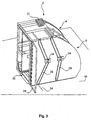
- Fig. 1 shows a monument according to the invention 2 with a first housing part 4 and a second housing part 6.
- the first housing part 4 is fixed to a bottom side 8 on a cabin floor 10.
- the second housing part 6 has on a connecting side 12 a cross section, which allows insertion of the second housing part 6 in a connecting side 14 of the first housing part 4.
- the housing part 4 and the second housing part together form a housing which defines the outer dimensions of the monument 2 according to the invention.
- Monument 2 of the invention reaches its minimum size.
- the monument 2 according to the invention reaches its maximum size.
- the second housing part 6 has locking means 16. These could be designed as a locking body 18, which can be introduced into corresponding corresponding bolt body receptacles 20 of the cabin floor 10 or a cabin ceiling, not shown.
- a side surface 22 of the second housing part 6 is equipped with two actuating devices 24 designed as handles, which each move the locking means 16 via movement means 26.
- the movement means 26 could be linear, such as push rods executed.
- the monument 2 according to the invention has an access opening 30 which runs parallel to an extension direction 32 of the monument 2 according to the invention. If the first cladding element 28 were fixedly arranged on the second housing part 6, it would close the access opening 30 in a collapsed state of the monument 2 according to the invention. However, the first cladding element 28 is adapted to be used only when needed, so that it does not obstruct the access opening 30 in a collapsed state of the monument 2 according to the invention.
- the displacement of the second housing part 6 can optionally take place by means of a drive device 31, which is arranged merely by way of example on the upper side of the monument 2 according to the invention.
- the drive device 31 may have any mode of operation and implement a movement approximately electrically, pneumatically or hydraulically.
- the first cladding element 28 can be activated as a pivotally mounted door or flap and arranged on the second housing part 6 to the gap between the first housing part 4 and the second housing part 6 in the second relative position, that is at maximum extended second Housing part 6, to dress. If the second housing part 6 is in the first relative position to the first housing part 4, the first cladding element 28 can be folded against the side surface 22 of the second housing part 6.
- the actuators 24 for actuating the locking means 16 are preferably positioned on the surface 22 such that they are not impaired by the unfolded covering means 28 in their function.
- the cladding element 28 can be seen in a folded-down position, which allows the second housing part 6 to be pulled out of the first housing part 4.
- the cabin floor 10 and / or the first housing part 4 and / or the second housing part 6 could have suitable guide means 34 for simplifying the extraction, for example, designed as a sliding or roller rail or in the manner of a drawer extension between the first housing part 4 and the second housing part 6 could be, from which the entire load of the second housing part 6 are received.
- the second housing part 6 can be easily pulled out of the first housing part 4, that even a single vehicle companion, such as a stewardess in an aircraft, the displacement of the second housing part 6 is possible.
- hinged or deactivatable cladding elements are required only in the housing area with the access opening 30.
- two ceiling elements arranged on corresponding housing parts 4 or 6 can simply be displaced relative to one another.
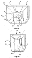
- a first sanitary object 36 is shown, which could be arranged in the monument 2 according to the invention and advantageously use the variable space comfortably.
- the first sanitary object 36 has an outlet 38, which is connected to a drain line 40.
- the drain line 40 has a first drain line section 42, a second drain section 44 and a joint 46 arranged between the two drain sections 42 and 44.
- the first drainage portion 42 is also hinged to the drain 38.
- the second discharge section 44 is articulated to an outflow port 48, which is located at a predetermined position within the monument 2 according to the invention.
- the drain line 40 and thus the drain line sections 42 and 44 can be made of a rigid material so that the drain line 40 does not collapse when the vacuum is applied.
- the first sanitary object 36 could, for example, be located inside the monument 2 according to the invention when the first relative position of the second housing part 6 relative to the first housing part 4 is assumed, as shown in FIG Fig. 4b shown.
- a guide means 50 is preferably arranged in the monument 2 according to the invention, which could be designed as a rail on which a sliding element 51 is displaceable. This mechanism could be extended to hold the first sanitary article 36 in a first operating position and in a second operating position by means of locking elements 47 and 49 arranged at predetermined positions.
- the movement and locking of the first sanitary article 36 may be coupled to the movement of the second housing part 6 such that automatically when enlarging or reducing the size of the monument 2 according to the invention, the first sanitary article 36 is automatically located at its proper operating position.
- This can also, as in Fig. 1 . 2 . 3a and 3b shown to be realized by the drive means 31.
- the first sanitary article 36 may also be displaced and locked by an independent drive means not shown in the figures.
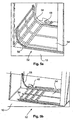
- Fig. 5a and 5b further show a flexible floor 52 consisting of a straight floor section 54 and a plurality of finned floor sections 56 articulated thereto. If the second housing part is in the first relative position, the excess portion of the floor 52, ie the length of the floor 52 that extends beyond the extent of the inventive monument 2, is guided into a region of the monument 2 according to the invention with the aid of a receiving means 58, embodied as an example as a guide rail. in which the unnecessary floor sections 56 are no longer visible to the user of the monument 2 according to the invention. This could be, for example, below a storage compartment or the like.
- the advantage of such a floor 52 is that the entire floor area of the monument 2 according to the invention has a continuous floor covering, so that an underlying floor covering of the vehicle is not soiled in any relative position by the user of the monument 2 according to the invention. It will be understood by one of ordinary skill in the art that other types of flooring 52 and containment means 58 could be used in the monument of the invention. Thus, fully elastic floors 52 could be taken up by receiving means 58, which were designed as rollers or rollers, or released again as needed.
- the monument 2 according to the invention could have, for example, a first sanitary object 36 which can be used in each operating mode of the monument 2 according to the invention.
- a first sanitary object 36 which can be used in each operating mode of the monument 2 according to the invention.
- the collapsed state of the first sanitary object 36 is positioned closely adjacent to an outer wall of the monument according to the invention, so that the space required for the monument 2 according to the invention in an inserted state is not excessively large.
- the first sanitary object 36 slightly detached from this outer wall of the monument 2 according to the invention, so that a use of the first sanitary article 36 is facilitated.
- the second sanitary object 60 Since there is a free space within the monument according to the invention in the ejected state, it would be possible to operate within this free space an additional second sanitary object 60, which is designed approximately as a urinal. So that it does not bother in the unused state or repels passengers within the monument according to the invention, the second sanitary object can be arranged pivotably within a trim 62. In order to prevent swiveling out of the second sanitary object 60 in the collapsed state, a lock could be arranged in the covering 62, which blocks the second sanitary object 60 in this state.
- the swinging out of the second sanitary object can be carried out by any actuating means, such as a knob or a non-contact proximity sensor.
- a floor covering 59 can be seen, which is arranged on the actual flexible floor.
- the floor covering 59 is adapted to form, in combination with an edge region 61 of the floor, a type of floor pan which prevents escape of dirt and liquids to the outside.
- Fig. 7 1 also shows an aircraft 64 having a passenger cabin and a plurality of monuments 2 according to the invention, which are arranged only by way of example therein and which are located both in areas of passenger cabin doors 66 and in areas in the middle of the passenger compartment Passenger cabin can be arranged.
- a maximum amount of comfort is provided in the monuments 2 according to the invention during the trip flight, however, a sufficiently rapid boarding is always permitted during the floor stay.
Landscapes
- Engineering & Computer Science (AREA)
- Aviation & Aerospace Engineering (AREA)
- Vehicle Waterproofing, Decoration, And Sanitation Devices (AREA)
- Residential Or Office Buildings (AREA)
- Tents Or Canopies (AREA)
- Vehicle Step Arrangements And Article Storage (AREA)
- Body Structure For Vehicles (AREA)
- Specific Sealing Or Ventilating Devices For Doors And Windows (AREA)
Claims (18)
- Structure (2) pour une cabine d'un véhicule, la structure (2) présentant :- une première partie de boîtier (4) avec un côté inférieur (8) et un côté de liaison (12) ;- une seconde partie de boîtier (6) avec un côté inférieur et un côté de liaison (14) et- au moins un premier élément de revêtement (28) ;dans laquelle la première partie de boîtier (4) est mise en place de manière à être fixée avec son côté inférieur (8) à un sol (10) de la cabine,
dans laquelle pour insérer l'une des parties de boîtier (4, 6) dans l'autre partie de boîtier (4, 6) une section extérieure du côté de liaison (12, 14) d'une des parties de boîtier (4, 6) est dimensionnée plus petite qu'une section d'ouverture du côté de liaison (12, 14) de l'autre partie de boîtier (4, 6) et la première partie de boîtier (4) et la seconde partie de boîtier (6) forment un boîtier,
dans laquelle la première partie de boîtier (4) et/ou la seconde partie de boîtier (6) présente des moyens de verrouillage (16) pour arrêter la seconde partie de boîtier (6) dans une première position relative et dans une seconde position relative par rapport à la première partie de boîtier (4) ; et
dans laquelle le premier élément de revêtement (28) est disposé sur la première partie de boîtier (4) ou la seconde partie de boîtier (6) pour recouvrir une fente entre le côté de liaison de la première partie de boîtier (4) et de la seconde partie de boîtier (6) dans la seconde position relative ;
présentant en outre un premier objet d'équipement qui est disposé de manière mobile dans le boîtier et peut être arrêté dans une première position de fonctionnement et dans une seconde position de fonctionnement ;
dans laquelle le premier objet d'équipement est un premier objet sanitaire (36) comportant une évacuation (38), et
dans laquelle l'évacuation (38) est reliée à un conduit d'évacuation (40) dont les extrémités sont mobiles l'une part rapport à l'autre. - Structure (2) selon la revendication 1, dans laquelle le moyen de verrouillage (16) est mis en place de manière à relier la première partie de boîtier (4) et la seconde partie de boîtier (6) l'une à l'autre de manière rigide si besoin.
- Structure (2) selon la revendication 1, dans laquelle le moyen de verrouillage (16) est mis en place de manière à relier la seconde partie de boîtier (6) si besoin au plancher de cabine (10) et/ou à un plafond de cabine.
- Structure (2) selon une des revendications précédentes, dans laquelle le moyen de verrouillage (16) présente un dispositif d'actionnement (24) pour activer ou désactiver le moyen de verrouillage (16).
- Structure (2) selon la revendication 4, dans laquelle le dispositif d'actionnement (24) est une poignée coulissante ou rotative qui déplace pour verrouiller par l'intermédiaire de moyens de déplacement (26) au moins un corps de verrou (18) dans au moins un logement de corps de verrou correspondant (20) et verrouille dans la position finale respective.
- Structure (2) selon une des revendications précédentes,
dans laquelle le premier élément de revêtement (28) est un élément de paroi disposé de manière mobile sur la première partie de boîtier (4) ou la seconde partie de boîtier (6). - Structure (2) selon une des revendications précédentes,
dans laquelle le boîtier présente un plancher souple (52) qui s'étend entre la première partie de boîtier (4) et la seconde partie de boîtier (6) et
dans laquelle la première partie de boîtier (4) et/ou la seconde partie de boîtier (6) présente des moyens de logement (58) pour arrimer et libérer une longueur de plancher excédentaire. - Structure (2) selon la revendication 7,
dans laquelle le plancher souple (52) présente au moins un premier segment fixe (54) et au moins un segment en forme de lamelles (56). - Structure (2) selon la revendication 7 ou 8,
dans laquelle le plancher (52) présente un revêtement de sol souple (59) qui forme une cuve par l'intermédiaire d'un rebord (61) du plancher. - Structure (2) selon une des revendications 7 à 9, présentant des moyens de guidage servant de moyens de logement (58) pour guider la longueur de plancher excédentaire en direction verticale dans une zone de bordure de la première partie de boîtier (4) et/ou de la seconde partie de boîtier (6).
- Structure (2) selon la revendication 10, dans laquelle le conduit d'évacuation (40) présente au moins une première pièce partielle de conduit d'évacuation (42) et une seconde pièce partielle de conduit d'évacuation (44) qui sont reliées l'une à l'autre par l'intermédiaire d'une articulation (46).
- Structure (2) selon une des revendications précédentes, dans laquelle la structure (2) est une structure de toilettes de bord.
- Structure (2) selon une des revendications précédentes, présentant en outre un second objet d'équipement disposé de manière mobile sur la première partie de boîtier (4) ou la seconde partie de boîtier (6),
dans laquelle le second objet d'équipement peut être amené dans une position d'utilisation et dans une position d'arrêt. - Structure (2) selon la revendication 13,
dans laquelle le boîtier est mis en place de manière à verrouiller le second objet d'équipement dans la position d'arrêt lors du positionnement dans la première position relative de la première partie de boîtier (4) par rapport à la seconde partie de boîtier (6). - Structure (2) selon la revendication 13 ou 14,
dans laquelle le second objet d'équipement est un second objet sanitaire (60), en particulier un urinoir. - Structure (2) selon une des revendications précédentes, conçue pour être montée dans une cabine passagers d'un avion (64).
- Utilisation d'une structure (2) selon une des revendications 1 à 16 dans une cabine passagers d'un véhicule.
- Avion (64), comportant une cabine passagers, au moins une porte de cabine passagers (66) et au moins une structure selon la revendication 1.
Priority Applications (1)
| Application Number | Priority Date | Filing Date | Title |
|---|---|---|---|
| EP14155620.9A EP2735509B1 (fr) | 2009-07-23 | 2010-07-22 | Monument pour cabine d'aéronef |
Applications Claiming Priority (3)
| Application Number | Priority Date | Filing Date | Title |
|---|---|---|---|
| US22803709P | 2009-07-23 | 2009-07-23 | |
| DE102009034406A DE102009034406A1 (de) | 2009-07-23 | 2009-07-23 | Monument für eine Kabine eines Fahrzeugs |
| PCT/EP2010/060635 WO2011009912A1 (fr) | 2009-07-23 | 2010-07-22 | Structure pour cabine d'un véhicule |
Related Child Applications (1)
| Application Number | Title | Priority Date | Filing Date |
|---|---|---|---|
| EP14155620.9A Division EP2735509B1 (fr) | 2009-07-23 | 2010-07-22 | Monument pour cabine d'aéronef |
Publications (2)
| Publication Number | Publication Date |
|---|---|
| EP2456667A1 EP2456667A1 (fr) | 2012-05-30 |
| EP2456667B1 true EP2456667B1 (fr) | 2014-02-19 |
Family
ID=43402418
Family Applications (2)
| Application Number | Title | Priority Date | Filing Date |
|---|---|---|---|
| EP14155620.9A Not-in-force EP2735509B1 (fr) | 2009-07-23 | 2010-07-22 | Monument pour cabine d'aéronef |
| EP10735287.4A Not-in-force EP2456667B1 (fr) | 2009-07-23 | 2010-07-22 | Structure pour cabine d'un vehicule |
Family Applications Before (1)
| Application Number | Title | Priority Date | Filing Date |
|---|---|---|---|
| EP14155620.9A Not-in-force EP2735509B1 (fr) | 2009-07-23 | 2010-07-22 | Monument pour cabine d'aéronef |
Country Status (5)
| Country | Link |
|---|---|
| US (1) | US8662444B2 (fr) |
| EP (2) | EP2735509B1 (fr) |
| CN (1) | CN102481977B (fr) |
| DE (1) | DE102009034406A1 (fr) |
| WO (1) | WO2011009912A1 (fr) |
Families Citing this family (22)
| Publication number | Priority date | Publication date | Assignee | Title |
|---|---|---|---|---|
| US20130099055A1 (en) * | 2011-10-24 | 2013-04-25 | Schneller, Inc. | Integrated lavatory pan for commercial aircraft |
| DE102012003713B4 (de) | 2012-02-24 | 2025-10-02 | Airbus Operations Gmbh | Toilettenmodul für ein Fahrzeug und ein Fahrzeug mit einer Fahrzeugkabine und mindestens einem Toilettenmodul |
| EP2664542A1 (fr) | 2012-05-18 | 2013-11-20 | Airbus Operations GmbH | Toilettes de véhicule |
| WO2014031915A1 (fr) * | 2012-08-23 | 2014-02-27 | Mag Aerospace Industries, Inc. | Solutions de stockage perfectionnées qui utilisent les toilettes d'un avion |
| US8720827B2 (en) * | 2012-09-25 | 2014-05-13 | The Boeing Company | Dual function lavatory door |
| CN103818556A (zh) * | 2012-11-16 | 2014-05-28 | 哈尔滨飞机工业集团有限责任公司 | 小型飞机多功能整体盥洗室 |
| US8888045B2 (en) * | 2013-01-15 | 2014-11-18 | The Boeing Company | Apparatus for a no touch lavatory door |
| EP2978666B1 (fr) * | 2013-03-26 | 2020-10-14 | Airbus Operations GmbH | Unité de toilettes |
| US9908623B2 (en) * | 2013-05-10 | 2018-03-06 | B/E Aerospace, Inc. | Wall mounted stowage compartment |
| EP2848531B1 (fr) * | 2013-09-11 | 2017-08-23 | Airbus Operations GmbH | Galerie extensible |
| US9688407B2 (en) * | 2013-10-03 | 2017-06-27 | The Boeing Company | Modular lavatory system |
| US10464677B2 (en) * | 2014-04-07 | 2019-11-05 | B/E Aerospace, Inc. | Aircraft modular lavatory system |
| DE102014104921A1 (de) * | 2014-04-07 | 2015-10-08 | Airbus Operations Gmbh | Haltesystem für eine bewegliche Komponente |
| US9862491B2 (en) * | 2014-04-07 | 2018-01-09 | B/E Aerospace, Inc. | Modular lavatory system optimized for narrow body commercial aircraft |
| EP2939923A1 (fr) | 2014-04-28 | 2015-11-04 | Airbus Operations GmbH | Ensemble de toilettes modulaire pour une cabine de véhicule, cabine de véhicule et d'aéronef comportant une cabine et au moins un agencement de toilettes modulaire |
| WO2016162918A1 (fr) * | 2015-04-06 | 2016-10-13 | 株式会社ジャムコ | Module de toilette pour avion |
| DE102015206713A1 (de) | 2015-04-15 | 2016-10-20 | Airbus Operations Gmbh | Bausatz und Verfahren für einen Gehäuseaufbau eines Monuments für eine Fahrzeugkabine |
| DE102015211813A1 (de) * | 2015-06-25 | 2016-12-29 | Airbus Operations Gmbh | Sanitärmodul mit Faltnische für ein Flugzeug und Flugzeugtürbereich |
| US10322806B2 (en) * | 2016-01-04 | 2019-06-18 | The Boeing Company | Sliding closet |
| US10112719B2 (en) * | 2016-03-18 | 2018-10-30 | The Boeing Company | Deployable clearance panel system, method, and assembly for a monument within an internal cabin of an aircraft |
| US10660492B2 (en) * | 2017-06-09 | 2020-05-26 | The Boeing Company | Lavatory debris removal |
| US20250002153A1 (en) * | 2023-06-29 | 2025-01-02 | B/E Aerospace, Inc. | Premium and accessible lavatory with increased door opening |
Family Cites Families (11)
| Publication number | Priority date | Publication date | Assignee | Title |
|---|---|---|---|---|
| US2650368A (en) * | 1950-06-08 | 1953-09-01 | Evans Randolph | Bathroom construction |
| US4589463A (en) | 1984-09-28 | 1986-05-20 | Falcon Jet Corporation | Expandable volume lavatory |
| US5658031A (en) * | 1995-08-25 | 1997-08-19 | Holiday Rambler Llc | Flexible plumbing assembly |
| US6007025A (en) | 1996-12-23 | 1999-12-28 | The Boeing Company | Stowable module airplane lavatory |
| US6079669A (en) * | 1997-03-24 | 2000-06-27 | The Boeing Company | Dual pivot expandable lavatory |
| JP3573707B2 (ja) * | 2000-11-22 | 2004-10-06 | 株式会社ジャムコ | 航空機用拡張式ラバトリーユニット |
| US6604709B1 (en) * | 2002-02-20 | 2003-08-12 | The Boeing Company | Dot (department of transportation) lavatory and shower combination |
| US7117646B2 (en) * | 2003-07-18 | 2006-10-10 | Triumph Boats, Inc. | Privacy enclosure |
| US6889936B1 (en) | 2003-11-17 | 2005-05-10 | The Boeing Company | Apparatus and methods for increasing useable space within aircraft lavatories |
| JP2006040399A (ja) | 2004-07-27 | 2006-02-09 | Funai Electric Co Ltd | 光ディスク装置 |
| DE102007009544B4 (de) * | 2007-02-27 | 2014-11-20 | Airbus Operations Gmbh | Vorrichtung zum Transport und zur medizinischen Versorgung von Patienten sowie zur medizinischen Notfallversorgung in einem Flugzeug |
-
2009
- 2009-07-23 DE DE102009034406A patent/DE102009034406A1/de not_active Withdrawn
-
2010
- 2010-07-22 EP EP14155620.9A patent/EP2735509B1/fr not_active Not-in-force
- 2010-07-22 CN CN201080032500.3A patent/CN102481977B/zh not_active Expired - Fee Related
- 2010-07-22 WO PCT/EP2010/060635 patent/WO2011009912A1/fr not_active Ceased
- 2010-07-22 EP EP10735287.4A patent/EP2456667B1/fr not_active Not-in-force
-
2012
- 2012-01-23 US US13/355,976 patent/US8662444B2/en not_active Expired - Fee Related
Also Published As
| Publication number | Publication date |
|---|---|
| WO2011009912A4 (fr) | 2011-03-31 |
| CN102481977B (zh) | 2015-04-08 |
| US8662444B2 (en) | 2014-03-04 |
| EP2735509A1 (fr) | 2014-05-28 |
| DE102009034406A1 (de) | 2011-02-03 |
| EP2456667A1 (fr) | 2012-05-30 |
| WO2011009912A1 (fr) | 2011-01-27 |
| EP2735509B1 (fr) | 2016-04-27 |
| CN102481977A (zh) | 2012-05-30 |
| US20120119029A1 (en) | 2012-05-17 |
Similar Documents
| Publication | Publication Date | Title |
|---|---|---|
| EP2456667B1 (fr) | Structure pour cabine d'un vehicule | |
| DE60108338T2 (de) | Erweiterbare Toiletteneinheit eines Flugzeuges | |
| WO2011101385A2 (fr) | Installation de toilettes pour moyen de transport | |
| EP2456650B1 (fr) | Tramway doté d'un siège rabattable supplémentaire pour la cabine de conduite | |
| DE60203014T2 (de) | Fahrzeugkabine zur unterbringung von passagieren | |
| DE102013108121A1 (de) | Trennwand für eine Fahrzeugkabine, eine Monumentenanordnung in einer Kabine eines Verkehrsmittels und ein Verkehrsmittel mit einer Kabine sowie mindestens einer darin angeordneten derartigen Trennwand | |
| EP1698552A1 (fr) | Disposition d'un premier et d'un deuxième élément | |
| DE102014102378A1 (de) | Modul für eine Luftfahrzeugkabine mit einem an einer Tür angebrachten Sitz | |
| DE102015208351B4 (de) | Baueinheit, umfassend eine Sitzeinrichtung und eine Halterung für die Sitzeinrichtung, zur Anordnung in einem Schienenfahrzeug, Verfahren zum Überführen der Sitzeinrichtung von einer Verstaustellung in eine Gebrauchsstellung sowie Schienenfahrzeug mit mindestens einer Baueinheit | |
| DE102014115462A1 (de) | Anordnung mit einer Trennvorrichtung in einer Kabine eines Fahrzeugs und Flugzeug mit einer Kabine und einer solchen Anordnung | |
| DE102015116804A1 (de) | Raumeffizientes Kabinensegment für ein Fahrzeug sowie eine Passagierkabine mit einer Mehrzahl von Sitzen und einem solchen Kabinensegment | |
| DE102017111913A1 (de) | Monumentenanordnung in einer Kabine eines Fahrzeugs, eine Kabine eines Fahrzeugs sowie ein Fahrzeug mit einer derartigen Kabine | |
| DE102005009750B4 (de) | Anordnung, umfassend einen Sitz und einen Flugbegleitersitz | |
| DE102014110808A1 (de) | Einrichtungseinheit für ein Fahrzeug sowie ein Fahrzeug mit einer solchen Einrichtungseinheit | |
| DE102016103825A1 (de) | Anordnung in einer Fahrzeugkabine mit einem Kabinenmonument mit zwei Zugangsöffnungen an zwei eine Schnittfläche ausbildenden Gängen | |
| DE102006049001A1 (de) | Sitzvorrichtung für ein Flugzeug | |
| EP3904207A1 (fr) | Module intégré pour un aéronef, ainsi qu'aéronef doté du module intégré | |
| DE202023102872U1 (de) | Campingfahrzeug | |
| EP3309009B1 (fr) | Dispositif de construction d'intérieur | |
| EP1195113B1 (fr) | Table du type escamotable | |
| EP3727265A1 (fr) | Siège pour véhicule d'intérêt général et spécial | |
| DE102012005712A1 (de) | Umkleidekabine in einem Flugzeug und Verfahren zum Umrüsten eines Flugzeugs mit einer Umkleidekabine | |
| DE102023113607B3 (de) | Campingfahrzeug | |
| DE102020100473A1 (de) | Inneneinrichtungsbaugruppe mit Stauraum auf einer Monumenttür, Monument und Fahrzeug mit einer Inneneinrichtungsbaugruppe | |
| DE102019135314B4 (de) | Schienenfahrzeugwagen mit anpassbarer Abteilaufteilung |
Legal Events
| Date | Code | Title | Description |
|---|---|---|---|
| PUAI | Public reference made under article 153(3) epc to a published international application that has entered the european phase |
Free format text: ORIGINAL CODE: 0009012 |
|
| 17P | Request for examination filed |
Effective date: 20120112 |
|
| AK | Designated contracting states |
Kind code of ref document: A1 Designated state(s): AL AT BE BG CH CY CZ DE DK EE ES FI FR GB GR HR HU IE IS IT LI LT LU LV MC MK MT NL NO PL PT RO SE SI SK SM TR |
|
| DAX | Request for extension of the european patent (deleted) | ||
| RIC1 | Information provided on ipc code assigned before grant |
Ipc: B64D 11/00 20060101ALI20130503BHEP Ipc: B64D 11/02 20060101AFI20130503BHEP |
|
| GRAP | Despatch of communication of intention to grant a patent |
Free format text: ORIGINAL CODE: EPIDOSNIGR1 |
|
| INTG | Intention to grant announced |
Effective date: 20130628 |
|
| GRAP | Despatch of communication of intention to grant a patent |
Free format text: ORIGINAL CODE: EPIDOSNIGR1 |
|
| INTG | Intention to grant announced |
Effective date: 20131010 |
|
| GRAS | Grant fee paid |
Free format text: ORIGINAL CODE: EPIDOSNIGR3 |
|
| GRAA | (expected) grant |
Free format text: ORIGINAL CODE: 0009210 |
|
| AK | Designated contracting states |
Kind code of ref document: B1 Designated state(s): AL AT BE BG CH CY CZ DE DK EE ES FI FR GB GR HR HU IE IS IT LI LT LU LV MC MK MT NL NO PL PT RO SE SI SK SM TR |
|
| REG | Reference to a national code |
Ref country code: GB Ref legal event code: FG4D Free format text: NOT ENGLISH |
|
| REG | Reference to a national code |
Ref country code: CH Ref legal event code: EP |
|
| REG | Reference to a national code |
Ref country code: AT Ref legal event code: REF Ref document number: 652765 Country of ref document: AT Kind code of ref document: T Effective date: 20140315 |
|
| REG | Reference to a national code |
Ref country code: IE Ref legal event code: FG4D Free format text: LANGUAGE OF EP DOCUMENT: GERMAN |
|
| REG | Reference to a national code |
Ref country code: DE Ref legal event code: R096 Ref document number: 502010006121 Country of ref document: DE Effective date: 20140410 |
|
| REG | Reference to a national code |
Ref country code: NL Ref legal event code: VDEP Effective date: 20140219 |
|
| REG | Reference to a national code |
Ref country code: LT Ref legal event code: MG4D |
|
| PG25 | Lapsed in a contracting state [announced via postgrant information from national office to epo] |
Ref country code: LT Free format text: LAPSE BECAUSE OF FAILURE TO SUBMIT A TRANSLATION OF THE DESCRIPTION OR TO PAY THE FEE WITHIN THE PRESCRIBED TIME-LIMIT Effective date: 20140219 Ref country code: NO Free format text: LAPSE BECAUSE OF FAILURE TO SUBMIT A TRANSLATION OF THE DESCRIPTION OR TO PAY THE FEE WITHIN THE PRESCRIBED TIME-LIMIT Effective date: 20140519 Ref country code: IS Free format text: LAPSE BECAUSE OF FAILURE TO SUBMIT A TRANSLATION OF THE DESCRIPTION OR TO PAY THE FEE WITHIN THE PRESCRIBED TIME-LIMIT Effective date: 20140619 |
|
| RIN2 | Information on inventor provided after grant (corrected) |
Inventor name: TRAUTMANN, FRANK Inventor name: WALLER, MICHAEL Inventor name: BEHLAU, GREGOR Inventor name: TAPPE, JUERGEN Inventor name: GRANZEIER, WERNER Inventor name: TERSTAL, ARNE Inventor name: RICHENBERGER, MICHAEL Inventor name: HOLST, CHRISTIAN Inventor name: ROSE, HASKO Inventor name: STURM, RALPH |
|
| PG25 | Lapsed in a contracting state [announced via postgrant information from national office to epo] |
Ref country code: PT Free format text: LAPSE BECAUSE OF FAILURE TO SUBMIT A TRANSLATION OF THE DESCRIPTION OR TO PAY THE FEE WITHIN THE PRESCRIBED TIME-LIMIT Effective date: 20140619 Ref country code: CY Free format text: LAPSE BECAUSE OF FAILURE TO SUBMIT A TRANSLATION OF THE DESCRIPTION OR TO PAY THE FEE WITHIN THE PRESCRIBED TIME-LIMIT Effective date: 20140219 Ref country code: FI Free format text: LAPSE BECAUSE OF FAILURE TO SUBMIT A TRANSLATION OF THE DESCRIPTION OR TO PAY THE FEE WITHIN THE PRESCRIBED TIME-LIMIT Effective date: 20140219 Ref country code: NL Free format text: LAPSE BECAUSE OF FAILURE TO SUBMIT A TRANSLATION OF THE DESCRIPTION OR TO PAY THE FEE WITHIN THE PRESCRIBED TIME-LIMIT Effective date: 20140219 Ref country code: SE Free format text: LAPSE BECAUSE OF FAILURE TO SUBMIT A TRANSLATION OF THE DESCRIPTION OR TO PAY THE FEE WITHIN THE PRESCRIBED TIME-LIMIT Effective date: 20140219 Ref country code: ES Free format text: LAPSE BECAUSE OF FAILURE TO SUBMIT A TRANSLATION OF THE DESCRIPTION OR TO PAY THE FEE WITHIN THE PRESCRIBED TIME-LIMIT Effective date: 20140219 |
|
| PG25 | Lapsed in a contracting state [announced via postgrant information from national office to epo] |
Ref country code: LV Free format text: LAPSE BECAUSE OF FAILURE TO SUBMIT A TRANSLATION OF THE DESCRIPTION OR TO PAY THE FEE WITHIN THE PRESCRIBED TIME-LIMIT Effective date: 20140219 Ref country code: HR Free format text: LAPSE BECAUSE OF FAILURE TO SUBMIT A TRANSLATION OF THE DESCRIPTION OR TO PAY THE FEE WITHIN THE PRESCRIBED TIME-LIMIT Effective date: 20140219 |
|
| PG25 | Lapsed in a contracting state [announced via postgrant information from national office to epo] |
Ref country code: RO Free format text: LAPSE BECAUSE OF FAILURE TO SUBMIT A TRANSLATION OF THE DESCRIPTION OR TO PAY THE FEE WITHIN THE PRESCRIBED TIME-LIMIT Effective date: 20140219 Ref country code: CZ Free format text: LAPSE BECAUSE OF FAILURE TO SUBMIT A TRANSLATION OF THE DESCRIPTION OR TO PAY THE FEE WITHIN THE PRESCRIBED TIME-LIMIT Effective date: 20140219 Ref country code: DK Free format text: LAPSE BECAUSE OF FAILURE TO SUBMIT A TRANSLATION OF THE DESCRIPTION OR TO PAY THE FEE WITHIN THE PRESCRIBED TIME-LIMIT Effective date: 20140219 Ref country code: EE Free format text: LAPSE BECAUSE OF FAILURE TO SUBMIT A TRANSLATION OF THE DESCRIPTION OR TO PAY THE FEE WITHIN THE PRESCRIBED TIME-LIMIT Effective date: 20140219 |
|
| REG | Reference to a national code |
Ref country code: DE Ref legal event code: R097 Ref document number: 502010006121 Country of ref document: DE |
|
| PG25 | Lapsed in a contracting state [announced via postgrant information from national office to epo] |
Ref country code: SK Free format text: LAPSE BECAUSE OF FAILURE TO SUBMIT A TRANSLATION OF THE DESCRIPTION OR TO PAY THE FEE WITHIN THE PRESCRIBED TIME-LIMIT Effective date: 20140219 Ref country code: PL Free format text: LAPSE BECAUSE OF FAILURE TO SUBMIT A TRANSLATION OF THE DESCRIPTION OR TO PAY THE FEE WITHIN THE PRESCRIBED TIME-LIMIT Effective date: 20140219 |
|
| PLBE | No opposition filed within time limit |
Free format text: ORIGINAL CODE: 0009261 |
|
| STAA | Information on the status of an ep patent application or granted ep patent |
Free format text: STATUS: NO OPPOSITION FILED WITHIN TIME LIMIT |
|
| 26N | No opposition filed |
Effective date: 20141120 |
|
| PG25 | Lapsed in a contracting state [announced via postgrant information from national office to epo] |
Ref country code: LU Free format text: LAPSE BECAUSE OF FAILURE TO SUBMIT A TRANSLATION OF THE DESCRIPTION OR TO PAY THE FEE WITHIN THE PRESCRIBED TIME-LIMIT Effective date: 20140722 |
|
| REG | Reference to a national code |
Ref country code: CH Ref legal event code: PL |
|
| REG | Reference to a national code |
Ref country code: DE Ref legal event code: R097 Ref document number: 502010006121 Country of ref document: DE Effective date: 20141120 |
|
| PG25 | Lapsed in a contracting state [announced via postgrant information from national office to epo] |
Ref country code: IT Free format text: LAPSE BECAUSE OF FAILURE TO SUBMIT A TRANSLATION OF THE DESCRIPTION OR TO PAY THE FEE WITHIN THE PRESCRIBED TIME-LIMIT Effective date: 20140219 |
|
| REG | Reference to a national code |
Ref country code: IE Ref legal event code: MM4A |
|
| PG25 | Lapsed in a contracting state [announced via postgrant information from national office to epo] |
Ref country code: CH Free format text: LAPSE BECAUSE OF NON-PAYMENT OF DUE FEES Effective date: 20140731 Ref country code: LI Free format text: LAPSE BECAUSE OF NON-PAYMENT OF DUE FEES Effective date: 20140731 |
|
| PG25 | Lapsed in a contracting state [announced via postgrant information from national office to epo] |
Ref country code: SI Free format text: LAPSE BECAUSE OF FAILURE TO SUBMIT A TRANSLATION OF THE DESCRIPTION OR TO PAY THE FEE WITHIN THE PRESCRIBED TIME-LIMIT Effective date: 20140219 |
|
| REG | Reference to a national code |
Ref country code: FR Ref legal event code: PLFP Year of fee payment: 6 |
|
| PG25 | Lapsed in a contracting state [announced via postgrant information from national office to epo] |
Ref country code: IE Free format text: LAPSE BECAUSE OF NON-PAYMENT OF DUE FEES Effective date: 20140722 |
|
| REG | Reference to a national code |
Ref country code: DE Ref legal event code: R082 Ref document number: 502010006121 Country of ref document: DE Representative=s name: LKGLOBAL | LORENZ & KOPF PARTG MBB PATENTANWAE, DE Ref country code: DE Ref legal event code: R082 Ref document number: 502010006121 Country of ref document: DE Representative=s name: KOPF WESTENBERGER WACHENHAUSEN PATENTANWAELTE , DE |
|
| PG25 | Lapsed in a contracting state [announced via postgrant information from national office to epo] |
Ref country code: MC Free format text: LAPSE BECAUSE OF FAILURE TO SUBMIT A TRANSLATION OF THE DESCRIPTION OR TO PAY THE FEE WITHIN THE PRESCRIBED TIME-LIMIT Effective date: 20140219 Ref country code: SM Free format text: LAPSE BECAUSE OF FAILURE TO SUBMIT A TRANSLATION OF THE DESCRIPTION OR TO PAY THE FEE WITHIN THE PRESCRIBED TIME-LIMIT Effective date: 20140219 |
|
| PG25 | Lapsed in a contracting state [announced via postgrant information from national office to epo] |
Ref country code: MT Free format text: LAPSE BECAUSE OF FAILURE TO SUBMIT A TRANSLATION OF THE DESCRIPTION OR TO PAY THE FEE WITHIN THE PRESCRIBED TIME-LIMIT Effective date: 20140219 Ref country code: BG Free format text: LAPSE BECAUSE OF FAILURE TO SUBMIT A TRANSLATION OF THE DESCRIPTION OR TO PAY THE FEE WITHIN THE PRESCRIBED TIME-LIMIT Effective date: 20140219 Ref country code: GR Free format text: LAPSE BECAUSE OF FAILURE TO SUBMIT A TRANSLATION OF THE DESCRIPTION OR TO PAY THE FEE WITHIN THE PRESCRIBED TIME-LIMIT Effective date: 20140520 |
|
| REG | Reference to a national code |
Ref country code: FR Ref legal event code: PLFP Year of fee payment: 7 |
|
| PG25 | Lapsed in a contracting state [announced via postgrant information from national office to epo] |
Ref country code: HU Free format text: LAPSE BECAUSE OF FAILURE TO SUBMIT A TRANSLATION OF THE DESCRIPTION OR TO PAY THE FEE WITHIN THE PRESCRIBED TIME-LIMIT; INVALID AB INITIO Effective date: 20100722 Ref country code: TR Free format text: LAPSE BECAUSE OF FAILURE TO SUBMIT A TRANSLATION OF THE DESCRIPTION OR TO PAY THE FEE WITHIN THE PRESCRIBED TIME-LIMIT Effective date: 20140219 Ref country code: BE Free format text: LAPSE BECAUSE OF FAILURE TO SUBMIT A TRANSLATION OF THE DESCRIPTION OR TO PAY THE FEE WITHIN THE PRESCRIBED TIME-LIMIT Effective date: 20140731 |
|
| REG | Reference to a national code |
Ref country code: AT Ref legal event code: MM01 Ref document number: 652765 Country of ref document: AT Kind code of ref document: T Effective date: 20150722 |
|
| PGFP | Annual fee paid to national office [announced via postgrant information from national office to epo] |
Ref country code: GB Payment date: 20160721 Year of fee payment: 7 |
|
| PG25 | Lapsed in a contracting state [announced via postgrant information from national office to epo] |
Ref country code: AT Free format text: LAPSE BECAUSE OF NON-PAYMENT OF DUE FEES Effective date: 20150722 |
|
| PGFP | Annual fee paid to national office [announced via postgrant information from national office to epo] |
Ref country code: FR Payment date: 20160721 Year of fee payment: 7 |
|
| GBPC | Gb: european patent ceased through non-payment of renewal fee |
Effective date: 20170722 |
|
| REG | Reference to a national code |
Ref country code: FR Ref legal event code: ST Effective date: 20180330 |
|
| PG25 | Lapsed in a contracting state [announced via postgrant information from national office to epo] |
Ref country code: GB Free format text: LAPSE BECAUSE OF NON-PAYMENT OF DUE FEES Effective date: 20170722 |
|
| PG25 | Lapsed in a contracting state [announced via postgrant information from national office to epo] |
Ref country code: FR Free format text: LAPSE BECAUSE OF NON-PAYMENT OF DUE FEES Effective date: 20170731 |
|
| PG25 | Lapsed in a contracting state [announced via postgrant information from national office to epo] |
Ref country code: MK Free format text: LAPSE BECAUSE OF FAILURE TO SUBMIT A TRANSLATION OF THE DESCRIPTION OR TO PAY THE FEE WITHIN THE PRESCRIBED TIME-LIMIT Effective date: 20140219 |
|
| PG25 | Lapsed in a contracting state [announced via postgrant information from national office to epo] |
Ref country code: AL Free format text: LAPSE BECAUSE OF FAILURE TO SUBMIT A TRANSLATION OF THE DESCRIPTION OR TO PAY THE FEE WITHIN THE PRESCRIBED TIME-LIMIT Effective date: 20140219 |
|
| PGFP | Annual fee paid to national office [announced via postgrant information from national office to epo] |
Ref country code: DE Payment date: 20190719 Year of fee payment: 10 |
|
| REG | Reference to a national code |
Ref country code: DE Ref legal event code: R119 Ref document number: 502010006121 Country of ref document: DE |
|
| PG25 | Lapsed in a contracting state [announced via postgrant information from national office to epo] |
Ref country code: DE Free format text: LAPSE BECAUSE OF NON-PAYMENT OF DUE FEES Effective date: 20210202 |