EP2457722A2 - Dispositif de compactage pour automates de reprise - Google Patents
Dispositif de compactage pour automates de reprise Download PDFInfo
- Publication number
- EP2457722A2 EP2457722A2 EP11007941A EP11007941A EP2457722A2 EP 2457722 A2 EP2457722 A2 EP 2457722A2 EP 11007941 A EP11007941 A EP 11007941A EP 11007941 A EP11007941 A EP 11007941A EP 2457722 A2 EP2457722 A2 EP 2457722A2
- Authority
- EP
- European Patent Office
- Prior art keywords
- spring
- holder
- counter
- spring element
- deflection
- Prior art date
- Legal status (The legal status is an assumption and is not a legal conclusion. Google has not performed a legal analysis and makes no representation as to the accuracy of the status listed.)
- Granted
Links
Images
Classifications
-
- B—PERFORMING OPERATIONS; TRANSPORTING
- B30—PRESSES
- B30B—PRESSES IN GENERAL
- B30B9/00—Presses specially adapted for particular purposes
- B30B9/32—Presses specially adapted for particular purposes for consolidating scrap metal or for compacting used cars
- B30B9/321—Presses specially adapted for particular purposes for consolidating scrap metal or for compacting used cars for consolidating empty containers, e.g. cans
-
- B—PERFORMING OPERATIONS; TRANSPORTING
- B30—PRESSES
- B30B—PRESSES IN GENERAL
- B30B9/00—Presses specially adapted for particular purposes
- B30B9/32—Presses specially adapted for particular purposes for consolidating scrap metal or for compacting used cars
- B30B9/321—Presses specially adapted for particular purposes for consolidating scrap metal or for compacting used cars for consolidating empty containers, e.g. cans
- B30B9/325—Presses specially adapted for particular purposes for consolidating scrap metal or for compacting used cars for consolidating empty containers, e.g. cans between rotary pressing members, e.g. rollers, discs
Definitions
- the invention relates to a compacting device for reverse vending machines for compacting empties with means for feeding the empties along a feed direction to a reduction, with a cutting unit arranged at the reduction and with a counter-holder for reducing the empties in the volume transverse to the feed direction, wherein the anvil over a Spring unit is arranged biased transversely to the feed direction.
- a compacting device for automatic reverse vending machines for compaction of empties which provides means for supplying empties to a reduction place, on which is reduced by cooperation of a cutting element with a counter-holder, the empties in its volume.
- the empties are pressed or crimped, for example, so that the empties permanently in its reduced flat shape remains and can then be stored in a downstream storage container to save space.
- the counter-holder is arranged biased transversely to the feed direction via a spring unit and allows as an abutment that the empties is forced through a reduction gap with reduction of the volume.
- the spring unit consists of a plastic spring, which acts on the counter-holder with a contact force transversely to the feed direction.
- the spring unit In order for relatively small empties to be compacted or reduced relatively reliably in cross-section, the spring unit must provide a relatively large spring force. However, if relatively large or thick empties are to be drawn through the reduction gap in the transverse direction, it may cause jamming due to the relatively large spring force that builds up, which prevents the empties from being conveyed further. For the continued operation of the compacting the relatively thick empties would have to be removed from the compacting, which is associated with a relatively large effort.
- Object of the present invention is therefore to develop a compacting device for reverse vending machines for compaction of empties so that a secure compaction of empties different transverse extent or wall thickness is ensured without the risk of jamming the empties is.
- the invention is characterized in connection with the preamble of claim 1, characterized in that the spring unit is designed such that upon deflection of the counter-holder, starting from a zero position, in a first deflection region of the counter-holder is subjected to an increasing spring force, and that after exceeding a transitional deflection by the counter-holder it is acted upon by further deflection in a second deflection range with a spring force whose spring force increase is smaller than a spring force increase in the first deflection range.
- the particular advantage of the invention is that can be compacted in a relatively wide transverse extension range or thickness range by the inventive design of a spring unit empties.
- a relatively large spring force increase acts on the counter-holder or the empties
- relatively thin empties can be securely compacted or spent in a relatively flat reduction state.
- a Grenzauslenkungsweges reaches a second deflection range, in which the spring force increase is lower than in the first deflection range, relatively thick empties can be compacted, without causing an undesirable jamming of the same in the compacting device.
- the basic idea of the invention is to provide an adapted pressure force for compacting it as a function of the transverse extent or thickness of the empties.
- the invention thus enables a setting of the pressing force adapted to the type of empties, which leads to the pressing in a flat reduction state of the same.
- the first deflection region of the counter-holder is dimensioned such that empties can be compacted with a small cross-section.
- a subsequent to the first deflection range second deflection region of the counter-holder has a reduced increase in spring force, so that empties can be compacted with a large cross-section.
- the compacting device allows two defined work areas, with a first working area for empties with a smaller cross section and a second work area for empties with a large cross section is provided. For different categories of empties can thus set an optimal contact pressure, which leads to a correspondingly flat pressing the empties.
- the spring unit has at least two spring elements, wherein a first spring element has a larger spring constant than a second spring element.
- a behavior of the spring unit adapted to the application can be set here, wherein a flattening of the spring characteristic line occurs in the second deflection region. If only two spring elements are used, the pitch of the spring characteristic curves in the first deflection region and the second deflection region is constant in each case. If more than two spring elements of different spring constants are used, the first deflection region and / or the second deflection region can also have sections having different spring characteristic slope. A further optimization of the pressure force can be provided thereby.
- a second spring element is biased to a biasing force corresponding to a maximum spring force of the first deflection range.
- a first spring element is biased to a biasing force that is smaller than the biasing force of the second spring element and greater than a minimum spring force.
- the pressing force is advantageous hereby set in the initial state of the counter-holder and the Mattergangsauslenkungsweg.
- the spring elements are designed as helical springs, which are arranged in series with each other.
- the spring elements are clamped between a base plate and the counter-holder, with corresponding clamping screws or threaded rods for adjusting the different spring elements.
- this can be done in a space-saving and handling technically simple way to adjust the spring forces.
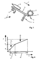
- a compacting apparatus 1 is integrated into a reverse vending machine which is set up in beverage or supermarkets to accept, compact and collect empties (preferably PET sheets) occupied by a deposit.
- the compacting device 1 consists essentially of a cutting unit 2, a counter-holder 3 and a spring unit 4, which are arranged at a reduction 5 of the reverse vending machine.
- the bottle-shaped empties 6 is fed via feed to the reduction 5 in the feed direction 7, wherein the empties 6 is fed sequentially to the reduction 5 by means of a non-illustrated driven impeller along the counter-holder 3.
- the cutting unit 2 is formed by a drivable cutting roller 2 whose axis of rotation is oriented perpendicular to the feed direction 7.
- the cutting roller 2 has a plurality of circumferentially distributed spikes 2 ', which press into the material of the empties 6 when the empties 6 reaches the reduction 5 and is pressed against the biased by the spring unit counter-holder 3, so that after leaving the Reduction site 5 a flat pressed or reduced in volume empties 6 a collecting container, not shown, can be fed.
- the counter-holder 3 is formed as a flat plate which is pivotally mounted about a pivot bearing 9.
- the pivot bearing 9 is arranged at a distance from the reduction location 5, preferably at a rear end of the counter-holder 3 in the feed direction 7.
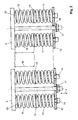
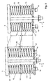
- the spring unit 4 has a pair of a first spring element 10 and a second spring element 11, wherein the two pairs of spring elements 10, 11 are arranged in a common plane which is perpendicular to the feed direction 7.
- the first spring element 10 and the second spring element 11 of the pair of spring elements 10, 11 are arranged in series with each other, between the anvil 3 and a base plate 12th
- the first spring element 10 is disposed on a side facing the anvil 3 and the second spring element 11 is disposed on a side facing the base plate 12.
- the first spring element 10 and the second spring element 11 are designed as helical springs.
- An end of the second spring element 11 facing the counter-holder 3 and an end of the first spring element 10 facing away from the counter-holder 3 are supported on opposite sides of a ring nut 13.
- the ring nut 13 has an internal thread, via which it is in threaded engagement with a clamping screw 14 supported on the base plate 12.
- the clamping screw 14 extends with its thread within the second spring element eleventh
- the second spring element 11 can be biased by a deflection s, so that the biasing force of the maximum force F2 of the first deflection region 18 corresponds.
- the clamping screw 14 is inserted through a bore 15 of the base plate 12.
- the first spring elements 10 can be biased.
- a threaded rod 16 arranged between adjacent pairs of spring elements 10, 11 is provided which is rotatably and axially fixed to the counter-holder 3 and is rotatably and axially movable relative to the base plate 12 via a thread.
- the threaded rod 16 with a clamping nut 17 is engaged, by means of which the base plate 12 in the direction of the counter-holder 3 is movable, so that the first spring elements 10 can be biased by tightening the clamping nut 17 ,
- the first spring elements 10 are biased by a deflection path s, so that in the first spring elements 10, a biasing force is set, which is smaller than the biasing force F2 of the second spring element eleventh
- first deflection region 18 of the counter-holder 3 for forming a first working region, in which a first spring constant D1 of the first spring element 10 is effective, and a second deflection region 19 for forming a second working region, in which a resulting spring constant D of the first spring element 10 and the second spring element 11 is effective, which is smaller than the first spring constant D1 of the first spring element 10 and as a second spring constant D2 of the second spring element 11, see FIG. 4 ,
- the resulting spring characteristic in the second deflection region 19 is flatter than the spring characteristic in the first deflection region 18 or a gradient D of the spring characteristic in the second deflection region 19 is smaller than a gradient D1 of the spring characteristic in the first deflection region 18.
- transitional deflection s 2 is formed such that in the first deflection region 18, such a spring force F acts on the counter-holder 3, that empties with a small cross-section are securely pressed or reduced on the one hand and that in the second deflection region 19 empties with a large cross-section without the risk of undesirable jamming of the same is pressed or reduced on the other hand.
- the set biasing force of the second spring element 11 corresponds to a maximum spring force F2 of the first deflection region 18.
- the biasing force of the first spring element 10 is smaller than the biasing force F2 of the second spring element 11 and greater than a predetermined minimum spring force, which causes the anvil 3 against the cutting roller 2 presses.
- the counter-holder 3 has on a base plate 12 side facing a centering cam 20 on which one end of the first spring element 10 is arranged centered.
- more than two pairs of spring elements 10, 11 may be provided. This is particularly useful when the cutting roller 2 has a relatively large length.
- more than two spring elements can be arranged in series, so that the spring characteristic has more than one kink.
- the spring elements 10, 11 are preferably made of a plastic material (PU material) or of a metal material.
Landscapes
- Engineering & Computer Science (AREA)
- Mechanical Engineering (AREA)
- Control Of Vending Devices And Auxiliary Devices For Vending Devices (AREA)
- Springs (AREA)
Applications Claiming Priority (1)
| Application Number | Priority Date | Filing Date | Title |
|---|---|---|---|
| DE102010060913A DE102010060913A1 (de) | 2010-11-30 | 2010-11-30 | Kompaktiervorrichtung für Rücknahmeautomaten |
Publications (3)
| Publication Number | Publication Date |
|---|---|
| EP2457722A2 true EP2457722A2 (fr) | 2012-05-30 |
| EP2457722A3 EP2457722A3 (fr) | 2013-11-06 |
| EP2457722B1 EP2457722B1 (fr) | 2015-08-05 |
Family
ID=44799490
Family Applications (1)
| Application Number | Title | Priority Date | Filing Date |
|---|---|---|---|
| EP11007941.5A Active EP2457722B1 (fr) | 2010-11-30 | 2011-09-30 | Dispositif de compactage pour automates de reprise |
Country Status (2)
| Country | Link |
|---|---|
| EP (1) | EP2457722B1 (fr) |
| DE (1) | DE102010060913A1 (fr) |
Cited By (1)
| Publication number | Priority date | Publication date | Assignee | Title |
|---|---|---|---|---|
| FR3015960A1 (fr) * | 2013-12-31 | 2015-07-03 | Plastic Omnium Cie | Compacteur a dechets |
Families Citing this family (1)
| Publication number | Priority date | Publication date | Assignee | Title |
|---|---|---|---|---|
| DE102016207702A1 (de) | 2016-05-04 | 2017-11-09 | Ernst Hombach Gmbh & Co. Kg | Kompaktierungsvorrichtung für Leergutrücknahmeautomaten |
Citations (1)
| Publication number | Priority date | Publication date | Assignee | Title |
|---|---|---|---|---|
| DE102006033615A1 (de) | 2006-04-21 | 2007-10-25 | Hermann Scharfen Maschinenfabrik Gmbh & Co. Kg | Einheit zum Kompaktieren von Hohlkörpern |
Family Cites Families (9)
| Publication number | Priority date | Publication date | Assignee | Title |
|---|---|---|---|---|
| US1509730A (en) * | 1922-08-01 | 1924-09-23 | William R Hughes | Hulling attachment for thrashing machines |
| US2675970A (en) * | 1952-12-22 | 1954-04-20 | Harold G Edwards | Crushing and flattening machine |
| GB2055790B (en) * | 1979-08-08 | 1983-01-12 | Miller J H | Selective recovery of light non-ferrous metal |
| US4358995A (en) * | 1980-09-02 | 1982-11-16 | Vivitar Corporation | Apparatus for crushing articles |
| US4516489A (en) * | 1982-06-24 | 1985-05-14 | Balcon Industries | Apparatus for crushing articles |
| DE29700368U1 (de) * | 1996-01-12 | 1997-03-06 | Egger, Ueli, Brissago | Vorrichtung zum Verringern des Volumens von hohlen Gegenständen, insbesondere PET-Flaschen |
| DE102006033617A1 (de) * | 2006-04-21 | 2007-10-25 | Hermann Scharfen Maschinenfabrik Gmbh & Co. Kg | Kompaktieranlage zum Kompaktieren von Hohlkörpern |
| DE102006031970A1 (de) * | 2006-07-11 | 2008-01-17 | Rolf Baumann | Vorrichtung zum Zerdrücken von Verpackungsmüll |
| US8091809B2 (en) * | 2009-03-24 | 2012-01-10 | Fellowes, Inc. | Shredder with jam proof system |
-
2010
- 2010-11-30 DE DE102010060913A patent/DE102010060913A1/de not_active Withdrawn
-
2011
- 2011-09-30 EP EP11007941.5A patent/EP2457722B1/fr active Active
Patent Citations (1)
| Publication number | Priority date | Publication date | Assignee | Title |
|---|---|---|---|---|
| DE102006033615A1 (de) | 2006-04-21 | 2007-10-25 | Hermann Scharfen Maschinenfabrik Gmbh & Co. Kg | Einheit zum Kompaktieren von Hohlkörpern |
Cited By (1)
| Publication number | Priority date | Publication date | Assignee | Title |
|---|---|---|---|---|
| FR3015960A1 (fr) * | 2013-12-31 | 2015-07-03 | Plastic Omnium Cie | Compacteur a dechets |
Also Published As
| Publication number | Publication date |
|---|---|
| DE102010060913A1 (de) | 2012-05-31 |
| EP2457722A3 (fr) | 2013-11-06 |
| EP2457722B1 (fr) | 2015-08-05 |
Similar Documents
| Publication | Publication Date | Title |
|---|---|---|
| EP0155619B1 (fr) | Procédé pour réaliser des liaisons de tôles | |
| DE60215809T2 (de) | Längenverstellbares stanzwerkzeug | |
| DE2918243C2 (de) | Ausdrehkopf | |
| DE102008057137B4 (de) | Kompaktiervorrichtung | |
| DE2718766B2 (de) | Stempel-Abstreifer-Anordnung | |
| EP0623417A2 (fr) | Matrice profilée, procédé pour sa fabrication et outil susceptible d'être utilisé pour la mise en oeuvre de ce procédé | |
| DE2216604B2 (de) | Vorrichtung zum einsetzen von stanzmuttern in werkstuecke | |
| EP1711288B2 (fr) | Dispositif d'assemblage | |
| EP2457722B1 (fr) | Dispositif de compactage pour automates de reprise | |
| DE112018007878T5 (de) | Streckbördelwerkzeug, Streckbördelverfahren unter Verwendung desselben und Bauteil mit Streckflansch | |
| AT513741A4 (de) | Biegewerkzeuge zum Vorbiegen und Zudrücken | |
| DE1937818A1 (de) | Verfahren und Vorrichtung zum Ausstanzen sechseckiger Rohlinge | |
| DE10035427B4 (de) | Vorrichtung zum Eindrücken von Schrauben | |
| DE3915281C1 (en) | Guiding and positioning arrangement for metal strip - has block with guide bore in lower part for piston, horizontal axis in upper part for spherical roller, etc. | |
| DE102012013771B4 (de) | Schneidwerkzeug und mit solchem ausgestattete Schneidvorrichtung | |
| DE112021004973T5 (de) | Vorrichtung und verfahren zur befestigung einer mutter an der innenfläche eines rohrelements | |
| EP2042751B1 (fr) | Procédé d'application d'un élément de fonction sur une pièce en tôle et composant d'ensemble | |
| DE102020212354B4 (de) | Presswerkzeug | |
| DE2344831B2 (de) | Verfahren zur Herstellung gekrümmter Fittings und Verwendung einer Einrichtung zur Durchführung des Verfahrens | |
| WO2012024805A1 (fr) | Procédé de formage d'un tronçon d'extrémité passant d'un matériau en barre | |
| DE102019134506B3 (de) | Strangpresse | |
| EP4716032A1 (fr) | Dispositif de connexion d'un élément de contact à un conducteur et procédé | |
| EP2042750B1 (fr) | Procédé d'application d'un élément de fonction sur une pièce en tôle et composant d'ensemble | |
| DE102023123858A1 (de) | Verfahren und Vorrichtung zur Herstellung eines beulstrukturierten Rohres | |
| EP2945777B1 (fr) | Dispositif d'enfoncement |
Legal Events
| Date | Code | Title | Description |
|---|---|---|---|
| PUAI | Public reference made under article 153(3) epc to a published international application that has entered the european phase |
Free format text: ORIGINAL CODE: 0009012 |
|
| AK | Designated contracting states |
Kind code of ref document: A2 Designated state(s): AL AT BE BG CH CY CZ DE DK EE ES FI FR GB GR HR HU IE IS IT LI LT LU LV MC MK MT NL NO PL PT RO RS SE SI SK SM TR |
|
| AX | Request for extension of the european patent |
Extension state: BA ME |
|
| PUAL | Search report despatched |
Free format text: ORIGINAL CODE: 0009013 |
|
| AK | Designated contracting states |
Kind code of ref document: A3 Designated state(s): AL AT BE BG CH CY CZ DE DK EE ES FI FR GB GR HR HU IE IS IT LI LT LU LV MC MK MT NL NO PL PT RO RS SE SI SK SM TR |
|
| AX | Request for extension of the european patent |
Extension state: BA ME |
|
| RIC1 | Information provided on ipc code assigned before grant |
Ipc: B30B 9/32 20060101AFI20131001BHEP |
|
| 17P | Request for examination filed |
Effective date: 20140616 |
|
| GRAP | Despatch of communication of intention to grant a patent |
Free format text: ORIGINAL CODE: EPIDOSNIGR1 |
|
| INTG | Intention to grant announced |
Effective date: 20140919 |
|
| GRAS | Grant fee paid |
Free format text: ORIGINAL CODE: EPIDOSNIGR3 |
|
| GRAP | Despatch of communication of intention to grant a patent |
Free format text: ORIGINAL CODE: EPIDOSNIGR1 |
|
| INTG | Intention to grant announced |
Effective date: 20150116 |
|
| GRAA | (expected) grant |
Free format text: ORIGINAL CODE: 0009210 |
|
| AK | Designated contracting states |
Kind code of ref document: B1 Designated state(s): AL AT BE BG CH CY CZ DE DK EE ES FI FR GB GR HR HU IE IS IT LI LT LU LV MC MK MT NL NO PL PT RO RS SE SI SK SM TR |
|
| REG | Reference to a national code |
Ref country code: GB Ref legal event code: FG4D Free format text: NOT ENGLISH |
|
| REG | Reference to a national code |
Ref country code: CH Ref legal event code: EP |
|
| REG | Reference to a national code |
Ref country code: AT Ref legal event code: REF Ref document number: 740459 Country of ref document: AT Kind code of ref document: T Effective date: 20150815 |
|
| REG | Reference to a national code |
Ref country code: IE Ref legal event code: FG4D Free format text: LANGUAGE OF EP DOCUMENT: GERMAN |
|
| REG | Reference to a national code |
Ref country code: DE Ref legal event code: R096 Ref document number: 502011007488 Country of ref document: DE |
|
| REG | Reference to a national code |
Ref country code: LT Ref legal event code: MG4D |
|
| REG | Reference to a national code |
Ref country code: NL Ref legal event code: MP Effective date: 20150805 |
|
| PG25 | Lapsed in a contracting state [announced via postgrant information from national office to epo] |
Ref country code: NO Free format text: LAPSE BECAUSE OF FAILURE TO SUBMIT A TRANSLATION OF THE DESCRIPTION OR TO PAY THE FEE WITHIN THE PRESCRIBED TIME-LIMIT Effective date: 20151105 Ref country code: GR Free format text: LAPSE BECAUSE OF FAILURE TO SUBMIT A TRANSLATION OF THE DESCRIPTION OR TO PAY THE FEE WITHIN THE PRESCRIBED TIME-LIMIT Effective date: 20151106 Ref country code: LT Free format text: LAPSE BECAUSE OF FAILURE TO SUBMIT A TRANSLATION OF THE DESCRIPTION OR TO PAY THE FEE WITHIN THE PRESCRIBED TIME-LIMIT Effective date: 20150805 Ref country code: LV Free format text: LAPSE BECAUSE OF FAILURE TO SUBMIT A TRANSLATION OF THE DESCRIPTION OR TO PAY THE FEE WITHIN THE PRESCRIBED TIME-LIMIT Effective date: 20150805 Ref country code: FI Free format text: LAPSE BECAUSE OF FAILURE TO SUBMIT A TRANSLATION OF THE DESCRIPTION OR TO PAY THE FEE WITHIN THE PRESCRIBED TIME-LIMIT Effective date: 20150805 |
|
| PG25 | Lapsed in a contracting state [announced via postgrant information from national office to epo] |
Ref country code: SE Free format text: LAPSE BECAUSE OF FAILURE TO SUBMIT A TRANSLATION OF THE DESCRIPTION OR TO PAY THE FEE WITHIN THE PRESCRIBED TIME-LIMIT Effective date: 20150805 Ref country code: RS Free format text: LAPSE BECAUSE OF FAILURE TO SUBMIT A TRANSLATION OF THE DESCRIPTION OR TO PAY THE FEE WITHIN THE PRESCRIBED TIME-LIMIT Effective date: 20150805 Ref country code: HR Free format text: LAPSE BECAUSE OF FAILURE TO SUBMIT A TRANSLATION OF THE DESCRIPTION OR TO PAY THE FEE WITHIN THE PRESCRIBED TIME-LIMIT Effective date: 20150805 Ref country code: PT Free format text: LAPSE BECAUSE OF FAILURE TO SUBMIT A TRANSLATION OF THE DESCRIPTION OR TO PAY THE FEE WITHIN THE PRESCRIBED TIME-LIMIT Effective date: 20151207 Ref country code: ES Free format text: LAPSE BECAUSE OF FAILURE TO SUBMIT A TRANSLATION OF THE DESCRIPTION OR TO PAY THE FEE WITHIN THE PRESCRIBED TIME-LIMIT Effective date: 20150805 Ref country code: IS Free format text: LAPSE BECAUSE OF FAILURE TO SUBMIT A TRANSLATION OF THE DESCRIPTION OR TO PAY THE FEE WITHIN THE PRESCRIBED TIME-LIMIT Effective date: 20151205 Ref country code: PL Free format text: LAPSE BECAUSE OF FAILURE TO SUBMIT A TRANSLATION OF THE DESCRIPTION OR TO PAY THE FEE WITHIN THE PRESCRIBED TIME-LIMIT Effective date: 20150805 |
|
| PG25 | Lapsed in a contracting state [announced via postgrant information from national office to epo] |
Ref country code: NL Free format text: LAPSE BECAUSE OF FAILURE TO SUBMIT A TRANSLATION OF THE DESCRIPTION OR TO PAY THE FEE WITHIN THE PRESCRIBED TIME-LIMIT Effective date: 20150805 |
|
| PG25 | Lapsed in a contracting state [announced via postgrant information from national office to epo] |
Ref country code: EE Free format text: LAPSE BECAUSE OF FAILURE TO SUBMIT A TRANSLATION OF THE DESCRIPTION OR TO PAY THE FEE WITHIN THE PRESCRIBED TIME-LIMIT Effective date: 20150805 Ref country code: CZ Free format text: LAPSE BECAUSE OF FAILURE TO SUBMIT A TRANSLATION OF THE DESCRIPTION OR TO PAY THE FEE WITHIN THE PRESCRIBED TIME-LIMIT Effective date: 20150805 Ref country code: IT Free format text: LAPSE BECAUSE OF FAILURE TO SUBMIT A TRANSLATION OF THE DESCRIPTION OR TO PAY THE FEE WITHIN THE PRESCRIBED TIME-LIMIT Effective date: 20150805 Ref country code: SK Free format text: LAPSE BECAUSE OF FAILURE TO SUBMIT A TRANSLATION OF THE DESCRIPTION OR TO PAY THE FEE WITHIN THE PRESCRIBED TIME-LIMIT Effective date: 20150805 Ref country code: DK Free format text: LAPSE BECAUSE OF FAILURE TO SUBMIT A TRANSLATION OF THE DESCRIPTION OR TO PAY THE FEE WITHIN THE PRESCRIBED TIME-LIMIT Effective date: 20150805 |
|
| REG | Reference to a national code |
Ref country code: CH Ref legal event code: PL |
|
| REG | Reference to a national code |
Ref country code: DE Ref legal event code: R097 Ref document number: 502011007488 Country of ref document: DE |
|
| PG25 | Lapsed in a contracting state [announced via postgrant information from national office to epo] |
Ref country code: RO Free format text: LAPSE BECAUSE OF FAILURE TO SUBMIT A TRANSLATION OF THE DESCRIPTION OR TO PAY THE FEE WITHIN THE PRESCRIBED TIME-LIMIT Effective date: 20150805 Ref country code: MC Free format text: LAPSE BECAUSE OF FAILURE TO SUBMIT A TRANSLATION OF THE DESCRIPTION OR TO PAY THE FEE WITHIN THE PRESCRIBED TIME-LIMIT Effective date: 20150805 |
|
| PLBE | No opposition filed within time limit |
Free format text: ORIGINAL CODE: 0009261 |
|
| STAA | Information on the status of an ep patent application or granted ep patent |
Free format text: STATUS: NO OPPOSITION FILED WITHIN TIME LIMIT |
|
| REG | Reference to a national code |
Ref country code: IE Ref legal event code: MM4A |
|
| 26N | No opposition filed |
Effective date: 20160509 |
|
| PG25 | Lapsed in a contracting state [announced via postgrant information from national office to epo] |
Ref country code: CH Free format text: LAPSE BECAUSE OF NON-PAYMENT OF DUE FEES Effective date: 20150930 Ref country code: IE Free format text: LAPSE BECAUSE OF NON-PAYMENT OF DUE FEES Effective date: 20150930 Ref country code: LI Free format text: LAPSE BECAUSE OF NON-PAYMENT OF DUE FEES Effective date: 20150930 |
|
| REG | Reference to a national code |
Ref country code: FR Ref legal event code: PLFP Year of fee payment: 6 |
|
| PG25 | Lapsed in a contracting state [announced via postgrant information from national office to epo] |
Ref country code: SI Free format text: LAPSE BECAUSE OF FAILURE TO SUBMIT A TRANSLATION OF THE DESCRIPTION OR TO PAY THE FEE WITHIN THE PRESCRIBED TIME-LIMIT Effective date: 20150805 |
|
| PG25 | Lapsed in a contracting state [announced via postgrant information from national office to epo] |
Ref country code: MT Free format text: LAPSE BECAUSE OF FAILURE TO SUBMIT A TRANSLATION OF THE DESCRIPTION OR TO PAY THE FEE WITHIN THE PRESCRIBED TIME-LIMIT Effective date: 20150805 |
|
| PG25 | Lapsed in a contracting state [announced via postgrant information from national office to epo] |
Ref country code: SM Free format text: LAPSE BECAUSE OF FAILURE TO SUBMIT A TRANSLATION OF THE DESCRIPTION OR TO PAY THE FEE WITHIN THE PRESCRIBED TIME-LIMIT Effective date: 20150805 Ref country code: HU Free format text: LAPSE BECAUSE OF FAILURE TO SUBMIT A TRANSLATION OF THE DESCRIPTION OR TO PAY THE FEE WITHIN THE PRESCRIBED TIME-LIMIT; INVALID AB INITIO Effective date: 20110930 Ref country code: BG Free format text: LAPSE BECAUSE OF FAILURE TO SUBMIT A TRANSLATION OF THE DESCRIPTION OR TO PAY THE FEE WITHIN THE PRESCRIBED TIME-LIMIT Effective date: 20150805 |
|
| PG25 | Lapsed in a contracting state [announced via postgrant information from national office to epo] |
Ref country code: CY Free format text: LAPSE BECAUSE OF FAILURE TO SUBMIT A TRANSLATION OF THE DESCRIPTION OR TO PAY THE FEE WITHIN THE PRESCRIBED TIME-LIMIT Effective date: 20150805 |
|
| PG25 | Lapsed in a contracting state [announced via postgrant information from national office to epo] |
Ref country code: BE Free format text: LAPSE BECAUSE OF NON-PAYMENT OF DUE FEES Effective date: 20150930 |
|
| REG | Reference to a national code |
Ref country code: FR Ref legal event code: PLFP Year of fee payment: 7 |
|
| PG25 | Lapsed in a contracting state [announced via postgrant information from national office to epo] |
Ref country code: TR Free format text: LAPSE BECAUSE OF FAILURE TO SUBMIT A TRANSLATION OF THE DESCRIPTION OR TO PAY THE FEE WITHIN THE PRESCRIBED TIME-LIMIT Effective date: 20150805 |
|
| REG | Reference to a national code |
Ref country code: AT Ref legal event code: MM01 Ref document number: 740459 Country of ref document: AT Kind code of ref document: T Effective date: 20160930 |
|
| PG25 | Lapsed in a contracting state [announced via postgrant information from national office to epo] |
Ref country code: LU Free format text: LAPSE BECAUSE OF NON-PAYMENT OF DUE FEES Effective date: 20150930 |
|
| PG25 | Lapsed in a contracting state [announced via postgrant information from national office to epo] |
Ref country code: AT Free format text: LAPSE BECAUSE OF NON-PAYMENT OF DUE FEES Effective date: 20160930 |
|
| PG25 | Lapsed in a contracting state [announced via postgrant information from national office to epo] |
Ref country code: MK Free format text: LAPSE BECAUSE OF FAILURE TO SUBMIT A TRANSLATION OF THE DESCRIPTION OR TO PAY THE FEE WITHIN THE PRESCRIBED TIME-LIMIT Effective date: 20150805 |
|
| REG | Reference to a national code |
Ref country code: FR Ref legal event code: PLFP Year of fee payment: 8 |
|
| PG25 | Lapsed in a contracting state [announced via postgrant information from national office to epo] |
Ref country code: AL Free format text: LAPSE BECAUSE OF FAILURE TO SUBMIT A TRANSLATION OF THE DESCRIPTION OR TO PAY THE FEE WITHIN THE PRESCRIBED TIME-LIMIT Effective date: 20150805 |
|
| PGFP | Annual fee paid to national office [announced via postgrant information from national office to epo] |
Ref country code: FR Payment date: 20190820 Year of fee payment: 9 |
|
| PG25 | Lapsed in a contracting state [announced via postgrant information from national office to epo] |
Ref country code: FR Free format text: LAPSE BECAUSE OF NON-PAYMENT OF DUE FEES Effective date: 20200930 |
|
| PGFP | Annual fee paid to national office [announced via postgrant information from national office to epo] |
Ref country code: DE Payment date: 20250825 Year of fee payment: 15 |
|
| PGFP | Annual fee paid to national office [announced via postgrant information from national office to epo] |
Ref country code: GB Payment date: 20250923 Year of fee payment: 15 |