EP2457847A2 - Module de distribution pour moyen de revêtement industriel - Google Patents
Module de distribution pour moyen de revêtement industriel Download PDFInfo
- Publication number
- EP2457847A2 EP2457847A2 EP12155704A EP12155704A EP2457847A2 EP 2457847 A2 EP2457847 A2 EP 2457847A2 EP 12155704 A EP12155704 A EP 12155704A EP 12155704 A EP12155704 A EP 12155704A EP 2457847 A2 EP2457847 A2 EP 2457847A2
- Authority
- EP
- European Patent Office
- Prior art keywords
- piston
- chamber
- component
- dispensing module
- module according
- Prior art date
- Legal status (The legal status is an assumption and is not a legal conclusion. Google has not performed a legal analysis and makes no representation as to the accuracy of the status listed.)
- Withdrawn
Links
Images


Classifications
-
- B—PERFORMING OPERATIONS; TRANSPORTING
- B65—CONVEYING; PACKING; STORING; HANDLING THIN OR FILAMENTARY MATERIAL
- B65D—CONTAINERS FOR STORAGE OR TRANSPORT OF ARTICLES OR MATERIALS, e.g. BAGS, BARRELS, BOTTLES, BOXES, CANS, CARTONS, CRATES, DRUMS, JARS, TANKS, HOPPERS, FORWARDING CONTAINERS; ACCESSORIES, CLOSURES, OR FITTINGS THEREFOR; PACKAGING ELEMENTS; PACKAGES
- B65D83/00—Containers or packages with special means for dispensing contents
- B65D83/14—Containers for dispensing liquid or semi-liquid contents by internal gaseous pressure, i.e. aerosol containers comprising propellant
- B65D83/68—Dispensing two or more contents
- B65D83/682—Dispensing two or more contents initially separated and subsequently mixed
-
- B—PERFORMING OPERATIONS; TRANSPORTING
- B65—CONVEYING; PACKING; STORING; HANDLING THIN OR FILAMENTARY MATERIAL
- B65D—CONTAINERS FOR STORAGE OR TRANSPORT OF ARTICLES OR MATERIALS, e.g. BAGS, BARRELS, BOTTLES, BOXES, CANS, CARTONS, CRATES, DRUMS, JARS, TANKS, HOPPERS, FORWARDING CONTAINERS; ACCESSORIES, CLOSURES, OR FITTINGS THEREFOR; PACKAGING ELEMENTS; PACKAGES
- B65D83/00—Containers or packages with special means for dispensing contents
- B65D83/14—Containers for dispensing liquid or semi-liquid contents by internal gaseous pressure, i.e. aerosol containers comprising propellant
- B65D83/60—Containers for dispensing liquid or semi-liquid contents by internal gaseous pressure, i.e. aerosol containers comprising propellant with contents and propellant separated
- B65D83/64—Containers for dispensing liquid or semi-liquid contents by internal gaseous pressure, i.e. aerosol containers comprising propellant with contents and propellant separated by pistons
Definitions
- Two-piston systems are also known. From the DE 20 2007 004 662 U1 for example, a container with two pistons is known, which are arranged one above the other and slide along the wall of the container. On the container a two-way pump is arranged. A first way of the pump opens at the upper end of the container. The second path terminates in a conduit which traverses the first piston and slides along the same latter. The first component is located in the space above the first piston, while the second component is in the space between the first and the second second piston is located. Also in this device, the risk of not promoting the two components in a sufficiently precise ratio, relatively large.
- the object of the invention is thus to provide a dispensing module containing a coating agent consisting of at least a first and a second component, which makes it possible to separate the components of the coating before use and, if necessary, to apply the components uniformly and in a defined ratio to a material surface.
- the dispensing module is to prevent possible malfunction in the event of deformation of the container and allow a free choice of container shape.
- a dispensing module of the aforementioned type wherein the coupling means according to the invention comprise a part which connects the first piston to the second piston, wherein the first piston, the part and the second piston form a piston unit, wherein the first chamber is annular is formed and limited in its central region by the part of the piston unit and wherein the second chamber is concentric with the first chamber and arranged above it and the first piston and / or the second piston having a piston head, initially separated from the coupling means and after filling the dispensing module with the components is irreversibly connected to the coupling means.
- the first chamber is filled with the first component of the coating agent, the second chamber with the second component of the coating agent.
- the inventive solution ensures that a coating agent consisting of at least two components, the components of which are present before use in separate chambers, if necessary, can be applied uniformly and with a defined ratio of the components to a material surface.
- a coating agent consisting of at least two components, the components of which are present before use in separate chambers, if necessary, can be applied uniformly and with a defined ratio of the components to a material surface.
- the first and the second component of the coating agent in each case have functional groups which react chemically with one another during the mixing of the components. It is advantageous here that chemical reactions during storage in the delivery module are prevented, the occurrence of which is desired only when the mixture of the two components is applied. Thus, an optimal application of the mixture of components, in addition to good end product properties is possible. Such chemical reactions lead for example, for gas release and the associated foaming of the mixture, for gelation or solidification and curing of the coating. Also color changes or special haptic effects of the coating are possible desired consequences that occur only in the application.
- the components can also have no functional groups which can chemically react with one another during the mixing of the components. It is advantageous that incompatible or non-storable components are mixed only during the application and thus negative effects, such as phase separations are avoided. Moreover, when blending the components, physical effects, such as changes in temperature, viscosity, color or state of aggregation, which are advantageous in the application, can be caused.
- the ratio of the volumes of the first and the second component is in the range between 20: 1 to 1:20, preferably between 10: 1 to 1:10 and particularly preferably between 5: 1 to 1: 5.
- a defined ratio of the volumes can be realized by the appropriate choice of the base areas of the piston of the dispensing module.
- the dispensing module according to the invention makes it possible to meter the coating components uniformly in the selected volume ratio.
- the first component comprises at least one compound selected from the group of isocyanate prepolymers, silane-terminated prepolymers, polyurethanes, anionic, cationic or nonionic polyurethane dispersions, polyureas, polyacrylates, anionic, cationic or nonionic polyacrylate dispersions, polymethacrylates, polyacrylamides, Polyamides, polyesters, polyethers, polysiloxanes, polyvinyl alcohols, epoxy resins, bituminous emulsions, phenol-formaldehyde resins, aminoplasts, ABS resins, alkyd resins, melamine resins, phenolic resins, vinyl ester resins, oils, solid lubricants, bonded coatings, thixotropic agents and preferably at least one compound from the group of isocyanate prepolymers, silane-terminated Prepolymers, anionic, cationic or nonionic polyurethane dispersions, anionic,
- the second component typically comprises at least one compound from the group of polyurethanes, anionic, cationic or nonionic polyurethane dispersions, polyacrylates, anionic, cationic or nonionic polyacrylate dispersions, polymethacrylates, polyacrylamides, polyamides, polyesters, polyethers, polysiloxanes, polyvinyl alcohols, crosslinking agents, catalysts , Initiators, antioxidants, water, aqueous or alcoholic solutions, polyols, (poly) amines, oils, solid lubricants, bonded coatings, thixotropic agents and preferably at least one compound from the group cross-linking agents, catalysts, water, aqueous or alcoholic solutions, initiators, thixotropic agents , Polyols, antioxidants and most preferably crosslinking agents, catalysts, water, aqueous or alcoholic solutions, initiators.
- propellant gases are dissolved for foaming the components in the first and / or second component.
- Suitable propellants are in particular carbon dioxide, dinitrogen monoxide and liquefied gases such as hydrocarbons, for example propane, butane, isopentane, dimethyl ether and / or fluorine hydrocarbons.
- An embodiment of the invention is that the mixture of the first and the second component has adhesive properties.
- the mixing of the components has adhesive properties when it adheres to material surfaces by adhesion and thus joining parts can be firmly bonded together.
- the first component in this case preferably comprises at least one compound from the group of isocyanate prepolymers, polyurethane dispersions, polyacrylate dispersions and the second component preferably at least one compound from the group of crosslinking agents, initiators, thixotropic agents.
- a further embodiment of the invention is that the mixture of the first and the second component is a foam, in particular an insulating foam or insulating foam.
- a foam is a three-dimensional network in which gas bubbles are separated by solid walls.
- the first component preferably comprises at least one compound from the group isocyanate prepolymer, silane-terminated prepolymers and the second component preferably at least one compound from the group crosslinking agents, catalysts, aqueous or alcoholic solutions.
- the mixture of the first and second components may be a protective film.
- a protective film is a thin layer that is applied to a surface to protect it from external influences that would cause damage or material changes.
- the film may seal or be permeable to certain substances.
- the first component in this case preferably comprises at least one compound from the group of polyurethane dispersions, alkyd resins, polyacrylates and the second component preferably at least one compound from the group of catalysts, antioxidants, crosslinking agents.
- the mixture of the first and the second component gives a sealant.
- a sealant is a material for sealing joints, gaps and openings.
- the first component preferably comprises at least one compound from the group of polysiloxanes, isocyanate prepolymers, silane-terminated prepolymers and the second component preferably comprises at least one compound from the group of catalysts, initiators, polyols.
- the mixture of the first and the second component gives a lubricant.
- Lubricants are materials that are used to reduce friction and wear, as well as for power transmission, cooling and vibration damping.
- the first component preferably comprises a mineral oil and the second component preferably comprises a thixotropic agent.
- Another object of the invention is the use of the dispensing module according to the invention for the coating of two- or three-dimensional material surfaces, consisting of metal, glass, ceramics, mineral, rock, wood, concrete, natural stone, leather, textile materials and / or plastic and particularly preferably from Mineral, rock, wood, plastic, metal and / or leather.
- the first and the second wall are cylindrical, but other embodiments are conceivable, for example, walls with an oval cross-section.
- An embodiment of the invention is that the coupling means pass through the first chamber and bring the side facing away from the opening of the first chamber side of the first piston with the side facing away from the opening of the second chamber side of the second piston in contact.
- fastening means are provided to connect the dispensing module to removal means or means for closing the openings of the chambers.
- the part which connects the first piston to the second piston is preferably cylindrical, and here, according to the design of the wall, other configurations are also conceivable.
- removal means are provided which are in communication with the openings of the chambers.
- the extraction means comprise a two-way valve or a two-way pump, wherein the first path with the opening of the first chamber and the second path is in communication with the opening of the second chamber.
- the removal means comprise a metering device.
- closing means are provided to close the openings of the first chamber and the second chamber, wherein the closing means have an open and a closed position.
- a housing is provided, which is attached to the dispensing module or to the removal means or to the closing means.
- the invention relates to a dispensing module (1) with two chambers (20, 30), which is attached to a valve (4) of a container (5), preferably a pressure vessel.
- a dispensing module (1) with two chambers (20, 30), which is attached to a valve (4) of a container (5), preferably a pressure vessel.
- Each chamber (20, 30) is provided with a piston (61, 64 and 7).
- Coupling means are provided for coupling the two pistons (61, 64 and 7) together after filling the chambers so that they move simultaneously.
- the valve (4) is preferably a two-way valve, so that the component contained in the first chamber (20) only with the exit from the valve (4) or possibly only at the exit from the valve (4) fixed outlet opening with the component of the second chamber (30) comes into contact.
- the invention also relates to the dispensing module (1) mounted on a valve (4) and the container comprising a valve (4) provided with a dispensing module (1) and mounted on a housing (5).
- the dispensing module (1) consists essentially of an outer shell (2), wherein in a part (21) of the same, the first piston (61) slides and the first chamber (20), of an inner shell (3), in the the second piston (64 and 7) slides and the second chamber (30) is formed of coupling means (62) for coupling the two pistons (61, 64 and 7) together and retaining means (8) for abutting the first one Serve piston (61).
- the outer shell (2) consists of a first, lower cylindrical part (21) and a second, upper cylindrical part (22) of smaller diameter.
- the two cylindrical parts are connected by a radial connecting wall (23).
- the wall of the second cylindrical part penetrating the radial wall (23), easily penetrates into the upper part of the first cylindrical part (21).
- This projection (25) serves as an upper stop for the first piston (61).
- the second cylindrical part (22) has in its upper region an annular radial shoulder (26) which is penetrated by one or more openings (261). It is thus achieved that the first jacket is tubular with openings at both ends.
- Channels (24) are arranged on the inside of the second cylindrical part (22). They extend over the entire height of this second part (22).
- the upper side of the second cylindrical part is provided with attachment means (27) with which the two-chamber delivery module (1) is attached to the two-way valve (4).
- These fastening means (27) comprise a crown, which is provided with locking means which can cooperate with complementary locking means on the two-way valve (4).
- the inner shell (3) consists essentially of a cylindrical main part (31) whose outer diameter substantially corresponds to the inner diameter of the second cylindrical part (22) of the outer shell (2).
- the cylindrical body portion (31) tapers in its upper portion, preferably by forming a frusto-conical wall (32), and terminates with a cylindrical portion forming a sleeve (33).
- the inner shell also has a tubular shape with openings at both ends.
- the sleeve (33) has an annular radial groove (331) which is open to the outside and the bottom diameter and height of the inner diameter and the height of the annular shoulder (26) of the second cylindrical part (22) of the outer shell (2) correspond.
- the inner shell (3) can be inserted inside the upper cylindrical wall (22) of the outer shell (2) until the sleeve (33) enters the opening in the center of the annular shoulder (26) and shoulder (26). engages in the groove (331).
- the inner shell (3) is fixed in this way inside the outer shell (2).
- the length of the inner shell (3) is chosen so that, with the position locked in the outer shell (2), the lower end is aligned with the lower end of the upper cylindrical part (22) of the outer shell (2).
- the inner shell (3) serves to define with the channels (24) the outlet lines for the component contained in the first chamber (20).
- the channels (24) are dimensioned so that they open in the space which is above the frusto-conical wall (32), but below the annular shoulder (26).
- the two pistons are combined in a piston unit (6).
- the first piston has a radial annular part (61) attached to the lower end of a cylindrical part (62).
- the radial annular part (61) has at its edge an axial rim (63) extending from the side of the annular part (61) facing away from the cylindrical part (62).
- the outer diameter of this ring (63) corresponds to the inner diameter of the first cylindrical part (21) of the outer shell.
- the ring (63) is provided with sealing means for sealing the piston (61) to the inside of the lower part (21) of the outer shell (2).
- These sealants are formed, for example, as flowable highly viscous sealants in the form of lubricants or as sealing lips (631), which consist for example of elastomeric materials.
- the outer diameter of the cylindrical part (62) of the piston unit (6) substantially corresponds to the inner diameter of the inner shell (3).
- the first chamber (20) by an annular space between on the one hand the cylindrical lower part (21) of the outer shell and the cylindrical part of the piston unit (62) and on the other hand between the first piston (61) and the radial part (23) the outer shell connecting the lower part (21) and the upper part (22) is formed.
- This first chamber (20) is open to the outside via the channels (24), the space between the frusto-conical part (32) of the inner shell and the shoulder (26) of the outer shell and the openings (261).
- An annular groove (611) is provided in the first piston (61) at the junction with the cylindrical part (62).
- the shape of this annular groove (611) is complementary to that of the projection (25) of the outer shell (2).
- the first piston (61) can slide inside the lower cylindrical part (21) of the outer shell (2).
- retaining means (8) are formed as an axial rim (81) whose inner diameter substantially corresponds to the outer diameter of the lower cylindrical part (21) of the outer shell.
- This axial rim (81) extends in its lower region via an annular radial wall (82) towards the center.
- the retaining means (8) are attached to the lower end of the lower part (21) of the outer shell (2), for example by means of locking means.
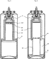
- the piston (61) can thus between a first position in which it abuts against the radial wall (23) of the outer shell (2) (see Fig. 3 ) and a second position in which its lower rim (63) abuts against the annular wall (82) of the retaining means (8) (see Fig. 4 ), be moved.
- the second piston (64) is formed by the top (64) of the cylindrical part (62) of the piston unit (6).
- This cylindrical part (62) thus serves as a coupling means, which make it possible to move the two pistons (61) and (64) simultaneously.
- a piston head (7) is attached to the top (64).
- the piston head in one piece directly at the top.
- the piston head (7) consists essentially of a radial circular wall (71), which is extended downwards by a ring (72). Sealants are provided on the outside of the ring in the form of sealing lips (721). The outer diameter of the ring (72) corresponds to the inner diameter of the cylindrical main part (31) of the inner shell (3).
- the second chamber (30) is defined by the space between on the one hand the inner side of the inner shell (3) and on the other hand the frusto-conical part (32) thereof and the piston (64 or 7). He is in the area of the upper opening of the Sleeve (33) open to the outside.
- the head (7) of the piston (64) also serves as a sealing ring for the upper part of the first chamber (20).
- the head (7) of the piston (64) is provided with locking means (722) which allow it to irreversibly lock on complementary latching means (641) which are arranged on the upper side (64) of the piston unit (6).
- These locking means (641, 722) are dimensioned so that a sufficiently strong pressure on the piston head (7) must be exercised so that it engages the top of the piston (64), and is preferably provided with one or more raster elements, the possible Can compensate for filling tolerances. This avoids unwanted locking, especially when storing or handling the empty dispensing modules.
- the height of the cylindrical body portion (31) of the inner shell (and thus the height of the upper cylindrical portion (22) of the outer shell) is selected so that when the piston unit (6) is in the upper position, the first one Plunger (61) abuts the radial connecting wall (23), there is sufficient space inside the inner shell for the cylindrical part (62) and the detached, not locked piston head (7).
- Such a two-chamber unit is intended to be mounted on dispensing means such as a two-way valve (4) or a two-way pump. It is also possible to provide only closing means which are opened during the dispensing process.
- the dispensing means may comprise dosing means such that upon actuation of the dispensing means a predetermined amount of each component is dispensed.
- Two-way valves are known, for example from the documents US 3,915,345 A or WO 2007/132 017 A1 , The example shown here is a two-way valve of the type described in the latter document. The operation of this valve is therefore not described in detail, but only the Particularities that arise in the context of its application in a two-chamber system according to the invention will be explained below.
- the valve body (41) comprises a first part in the form of a downwardly bulged collar (42) and a second central part in the form of a cylindrical pin (43), wherein the part in the form of the collar (42) surrounds the peg-shaped part (43) ,
- the collar-shaped part (42) is provided at its lower end with retaining means, which are complementary to those (27) of the outer shell (2).
- These holding means are dimensioned so that a tight connection between the outer shell (2) and the collar-shaped part (42) is provided.
- the pin-shaped part (43) is dimensioned so that it penetrates into the sleeve (33) of the inner shell and also ensures a tight connection.
- the valve is provided with two separate paths, one opening in the space between the collar (42) and the pin (43) and the other inside the pin (43).
- the unit consisting of the two-chamber delivery module (1) and the delivery means (4) can then be mounted in a housing (5). If the dimensions of the dispensing unit (1) and in particular the outer diameter of the outer jacket (2) and / or the diameter of the valve disc (44) of the dispensing means allow this, the dispenser module (1) can be inserted into the interior of a prefabricated housing. Otherwise, it is necessary to form the housing (5) around the dispensing module (1). This is the case with the example shown in the figures.
- a first advantage of the dispensing module is the fact that it is possible to use casings of any shape, in particular casings with a curved or profiled exterior.
- a second advantage is that deformations of the housing have no influence on the functioning of the pistons. While in the prior art, the slightest bump could hinder the sliding of the piston on the housing or its deformation could cause a leakage of the first chamber, the container provided with the dispensing module according to the invention is shock resistant.
- FIG. 3 shows a container provided with a dispensing module (1) attached to a two-way valve (4), the two-way valve (4) being mounted on the neck of the housing (5).
- the gas is already introduced into the housing and exerts a pressure on both the first piston (61) and on the second piston (64) or in the present case on the piston head (7).
- the container can now be filled with the two components.
- one begins by filling the first component via the first path of the dispensing means (4), then the openings (261) and the channels (24) in the first chamber (20).
- the piston unit (6) is pushed back by the incoming component pressing on the piston (61).
- the second piston has a separate piston head (7), it remains in its initial position, ie in the upper region of the second chamber (30), while the upper part (64) of the piston unit (6) is held by the first piston (7). 61) is pressed down.
- An opening (642) in the top of the piston unit (6) prevents the formation of a vacuum between the fixed piston head (7) and the downwardly extending top of the piston (64).
- the rim (63) of the first piston (61) abuts against the annular radial wall (82) of the retaining means (8), as in FIG FIG. 4 shown.
- the second component can now be filled via the second path of the valve (4) and the pin (43), and the sleeve (33) in the second chamber (30).
- the incoming component pushes the piston head (7) down.
- the gas in the space between the inside of the cylindrical part (62) of the piston unit is expressed via the opening (642) in the top part (64) of the piston unit.
- the pressure exerted by the second component on the piston head (7) is sufficient to overcome the resistance of the latching means (641, 722) and lock the piston head (7) into the piston unit (6).
- the two pistons (61, 64) are now coupled together and can only move simultaneously. This corresponds to the in FIG. 5 illustrated situation. It only needs a spray head on the rod (45) attached to the valve and possibly a Protective cap are applied.
- the container is ready for use. Thanks to the separate piston head (7) it is possible to fill the container with two separate filling units.
- the second piston is formed directly on top of the piston unit (6), this side has no opening (642), the shutdown of this top, which takes over the role of the piston, air in the second chamber (30), which forms simultaneously with the first one. Therefore, the air contained in this second, already formed chamber (30) must be sucked off before the second component is filled.
- the chambers (20, 30) form only when filling the components. If a separate piston head (7) is provided for the second chamber (30), this (30) will not be formed simultaneously with the first chamber (20). On the contrary, this forms only when filling with the second component. It is therefore not necessary to provide a suction device for removing the air from the second chamber before the second component is filled.
- the ratio between the initial volume of the first and second components is determined by the ratio between the area of the first (61) and second pistons (64).
- the dispensing module thus allows a very high precision in terms of the ratio of the initial volume of the two components. Due to the area ratio between the area of the first piston (61) and the second piston (64), it is also possible to fill the second chamber (30) with a higher pressure than the outside pressure.
- first piston (61) can also be formed with a separate piston head.
- the piston head is then annular and filling begins with the second chamber (30) and not with the first chamber (20), if only the first piston has such a piston head.
- the height of the first cylindrical portion (21) of the outer shell and / or the cylindrical portion (62) of the piston unit must be sufficiently large to allow the piston unit (6) to fully penetrate into the inner shell, with strikes her upper part without the annular piston head engages in the piston unit (6).
- the second piston (64) is also provided with a separate piston head (7).
- the dispensing module (1) is used on a pressure vessel, as is the case in the example shown here, then it may be useful to the unit consisting of the dispensing unit (1) and the dispensing means (4) in the housing (5) fasten, wherein the valve plate (44) is not mounted on the housing (5). This makes it possible to fill the propellant during filling before the valve plate (44) is mounted on the housing (5).
- a fork (9) is provided which blocks the unit so that the tip of the second cylindrical portion (22) of the outer shell abuts against the inner side of the top of the housing (5). This removable fork (9) penetrates into a groove (28), which is provided for this purpose at the top of the outer jacket (2) below the fastening means (27).
- valve plate (44) fastens the valve plate (44) to the housing (5) of the pressure vessel, then to fill the dispensing module (1) and to fill the gas via an opening in the bottom of the pressure vessel, which is subsequently closed. If the gas is filled from above, it must be ensured, for example through channels provided for this purpose, that the gas can flow to the bottom.
- Suitable propellant for discharging the components are, in particular, compressed gases, such as nitrogen, oxygen and compressed air, as well as liquefied gases, such as hydrocarbons, for example butane and isopentane, dimethyl ether and fluorine hydrocarbons.
- compressed gases such as nitrogen, oxygen and compressed air
- liquefied gases such as hydrocarbons, for example butane and isopentane, dimethyl ether and fluorine hydrocarbons.
- hydrocarbons for example butane and isopentane, dimethyl ether and fluorine hydrocarbons.
- elastomers restoring force
Landscapes
- Chemical & Material Sciences (AREA)
- Dispersion Chemistry (AREA)
- Engineering & Computer Science (AREA)
- Mechanical Engineering (AREA)
- Containers And Packaging Bodies Having A Special Means To Remove Contents (AREA)
- Coating Apparatus (AREA)
Priority Applications (1)
| Application Number | Priority Date | Filing Date | Title |
|---|---|---|---|
| EP12155704A EP2457847A3 (fr) | 2012-02-16 | 2012-02-16 | Module de distribution pour moyen de revêtement industriel |
Applications Claiming Priority (1)
| Application Number | Priority Date | Filing Date | Title |
|---|---|---|---|
| EP12155704A EP2457847A3 (fr) | 2012-02-16 | 2012-02-16 | Module de distribution pour moyen de revêtement industriel |
Publications (2)
| Publication Number | Publication Date |
|---|---|
| EP2457847A2 true EP2457847A2 (fr) | 2012-05-30 |
| EP2457847A3 EP2457847A3 (fr) | 2012-06-27 |
Family
ID=45655909
Family Applications (1)
| Application Number | Title | Priority Date | Filing Date |
|---|---|---|---|
| EP12155704A Withdrawn EP2457847A3 (fr) | 2012-02-16 | 2012-02-16 | Module de distribution pour moyen de revêtement industriel |
Country Status (1)
| Country | Link |
|---|---|
| EP (1) | EP2457847A3 (fr) |
Citations (4)
| Publication number | Priority date | Publication date | Assignee | Title |
|---|---|---|---|---|
| DE2007199A1 (de) | 1969-02-21 | 1970-09-03 | Fa. L'oreal, Paris | Verfahren zur gleichzeitigen Konditionierung und Verteilung von zwei fließfähigen Medien unter Druck und Behälter zur Durchführung des Verfahrens durch gleichzeitige Verschiebung von zwei Kolben |
| US3915345A (en) | 1971-05-11 | 1975-10-28 | Stanley Harrison | Aerosol can for dispensing materials in fixed volumetric ratio |
| WO2007132017A1 (fr) | 2006-05-16 | 2007-11-22 | Lindal France Sas | Valve à deux voies |
| DE202007004662U1 (de) | 2007-03-28 | 2008-08-07 | Geiberger, Christoph | Mehrkammerbehälter |
Family Cites Families (5)
| Publication number | Priority date | Publication date | Assignee | Title |
|---|---|---|---|---|
| CH337744A (fr) * | 1957-04-13 | 1959-04-15 | Maillard Jules | Appareil pour le mélange de proportions déterminées de matériaux |
| DE29905762U1 (de) * | 1999-03-29 | 1999-09-30 | Müller, Paul, Dübendorf | Vorrichtung zur getrennten Aufnahme und gemeinsamen Abgabe von Komponenten einer aushärtbaren Mehrkomponenten-Plaste |
| DE10132417A1 (de) * | 2001-07-04 | 2003-01-16 | Wella Ag | Vorrichtung zum gezielten Entnehmen von Teilmengen zweier flüssiger Produkte |
| WO2008109130A1 (fr) * | 2007-03-05 | 2008-09-12 | Robert Craig Virnelson | Distributeur de deux composants |
| EP2605857B1 (fr) * | 2010-08-16 | 2015-08-12 | Bayer MaterialScience AG | Module de distribution |
-
2012
- 2012-02-16 EP EP12155704A patent/EP2457847A3/fr not_active Withdrawn
Patent Citations (4)
| Publication number | Priority date | Publication date | Assignee | Title |
|---|---|---|---|---|
| DE2007199A1 (de) | 1969-02-21 | 1970-09-03 | Fa. L'oreal, Paris | Verfahren zur gleichzeitigen Konditionierung und Verteilung von zwei fließfähigen Medien unter Druck und Behälter zur Durchführung des Verfahrens durch gleichzeitige Verschiebung von zwei Kolben |
| US3915345A (en) | 1971-05-11 | 1975-10-28 | Stanley Harrison | Aerosol can for dispensing materials in fixed volumetric ratio |
| WO2007132017A1 (fr) | 2006-05-16 | 2007-11-22 | Lindal France Sas | Valve à deux voies |
| DE202007004662U1 (de) | 2007-03-28 | 2008-08-07 | Geiberger, Christoph | Mehrkammerbehälter |
Also Published As
| Publication number | Publication date |
|---|---|
| EP2457847A3 (fr) | 2012-06-27 |
Similar Documents
| Publication | Publication Date | Title |
|---|---|---|
| EP2605857B1 (fr) | Module de distribution | |
| EP2605858B1 (fr) | Module de distribution et procédé pour remplir un module de distribution | |
| EP1447140B1 (fr) | Dispositif de décharge pour produire manuellement un écoulement d'un volume donné | |
| DE10114624B4 (de) | Druckdose und ihre Verwendung für 2-Komponentensysteme | |
| EP3094414B1 (fr) | Dispositif de distribution | |
| EP1108439B1 (fr) | Distributeur de produit | |
| DE3151892A1 (de) | Handpumpe zur druckfoerderung von fluessigkeiten und/oder dickfluessigen substanzen aus einem behaelter | |
| DE202014001084U1 (de) | Abgabevorrichtung | |
| DE102009017459A1 (de) | Austragvorrichtung | |
| DE102011106261A1 (de) | Spender zur dosierten Abgabe von flüssigen Medien | |
| EP3048081B1 (fr) | Systeme de bloc de soupapes pour un appareil de fixation de bouteille | |
| DE202008007515U1 (de) | Fluidspender | |
| DE69805180T2 (de) | Druckknopf mit einer beweglichen düse zum austragen von unter druck stehenden flüssigkeiten | |
| DE102014011395A1 (de) | Vorrichtung zum Fördern von viskosem Material | |
| EP2457847A2 (fr) | Module de distribution pour moyen de revêtement industriel | |
| DE102007013723A1 (de) | Handbetätigter Spender für pastöse bis fluide Massen und Andockbehältnis hierfür | |
| DE102011005820A1 (de) | Austragvorrichtung | |
| EP2900391B1 (fr) | Dispositif de fourniture | |
| EP2393730B1 (fr) | Distributeur pour la distribution dosée d'une formulation de gaz liquéfié et procédé pour la fabrication du distributeur | |
| EP3717377B1 (fr) | Récipient sous pression à deux composants | |
| DE19947185C2 (de) | Injektionsspritze | |
| DE102023102632B4 (de) | Kartuschensystem zur Abgabe einer wässrigen Lösung | |
| EP2303470B1 (fr) | Dispositif distributeur | |
| DE102007029584A1 (de) | Vorrichtung zum Ausbringen einer von wenigstens zwei Komponenten durch Mischen gebildeten Masse | |
| DE102008064050A1 (de) | Mehrkomponentenkartusche |
Legal Events
| Date | Code | Title | Description |
|---|---|---|---|
| PUAL | Search report despatched |
Free format text: ORIGINAL CODE: 0009013 |
|
| PUAI | Public reference made under article 153(3) epc to a published international application that has entered the european phase |
Free format text: ORIGINAL CODE: 0009012 |
|
| AK | Designated contracting states |
Kind code of ref document: A2 Designated state(s): AL AT BE BG CH CY CZ DE DK EE ES FI FR GB GR HR HU IE IS IT LI LT LU LV MC MK MT NL NO PL PT RO RS SE SI SK SM TR |
|
| AX | Request for extension of the european patent |
Extension state: BA ME |
|
| AK | Designated contracting states |
Kind code of ref document: A3 Designated state(s): AL AT BE BG CH CY CZ DE DK EE ES FI FR GB GR HR HU IE IS IT LI LT LU LV MC MK MT NL NO PL PT RO RS SE SI SK SM TR |
|
| AX | Request for extension of the european patent |
Extension state: BA ME |
|
| RIC1 | Information provided on ipc code assigned before grant |
Ipc: B65D 83/14 20060101AFI20120521BHEP Ipc: B65D 83/64 20060101ALI20120521BHEP Ipc: B65D 83/68 20060101ALI20120521BHEP |
|
| STAA | Information on the status of an ep patent application or granted ep patent |
Free format text: STATUS: THE APPLICATION HAS BEEN WITHDRAWN |
|
| 18W | Application withdrawn |
Effective date: 20120907 |