EP2458088A2 - Dispositif déplaçable pour la solidification d'une structure en couches de sol et procédé de la détermination d'un module d'Young à couche d'une couche supérieure de ladite structure en couches de sol - Google Patents
Dispositif déplaçable pour la solidification d'une structure en couches de sol et procédé de la détermination d'un module d'Young à couche d'une couche supérieure de ladite structure en couches de sol Download PDFInfo
- Publication number
- EP2458088A2 EP2458088A2 EP11008033A EP11008033A EP2458088A2 EP 2458088 A2 EP2458088 A2 EP 2458088A2 EP 11008033 A EP11008033 A EP 11008033A EP 11008033 A EP11008033 A EP 11008033A EP 2458088 A2 EP2458088 A2 EP 2458088A2
- Authority
- EP
- European Patent Office
- Prior art keywords
- layer structure
- load
- detection
- detection means
- bottom layer
- Prior art date
- Legal status (The legal status is an assumption and is not a legal conclusion. Google has not performed a legal analysis and makes no representation as to the accuracy of the status listed.)
- Granted
Links
Images

Classifications
-
- E—FIXED CONSTRUCTIONS
- E01—CONSTRUCTION OF ROADS, RAILWAYS, OR BRIDGES
- E01C—CONSTRUCTION OF, OR SURFACES FOR, ROADS, SPORTS GROUNDS, OR THE LIKE; MACHINES OR AUXILIARY TOOLS FOR CONSTRUCTION OR REPAIR
- E01C19/00—Machines, tools or auxiliary devices for preparing or distributing paving materials, for working the placed materials, or for forming, consolidating, or finishing the paving
- E01C19/22—Machines, tools or auxiliary devices for preparing or distributing paving materials, for working the placed materials, or for forming, consolidating, or finishing the paving for consolidating or finishing laid-down unset materials
- E01C19/23—Rollers therefor; Such rollers usable also for compacting soil
- E01C19/28—Vibrated rollers or rollers subjected to impacts, e.g. hammering blows
- E01C19/288—Vibrated rollers or rollers subjected to impacts, e.g. hammering blows adapted for monitoring characteristics of the material being compacted, e.g. indicating resonant frequency, measuring degree of compaction, by measuring values, detectable on the roller; using detected values to control operation of the roller, e.g. automatic adjustment of vibration responsive to such measurements
-
- E—FIXED CONSTRUCTIONS
- E01—CONSTRUCTION OF ROADS, RAILWAYS, OR BRIDGES
- E01C—CONSTRUCTION OF, OR SURFACES FOR, ROADS, SPORTS GROUNDS, OR THE LIKE; MACHINES OR AUXILIARY TOOLS FOR CONSTRUCTION OR REPAIR
- E01C19/00—Machines, tools or auxiliary devices for preparing or distributing paving materials, for working the placed materials, or for forming, consolidating, or finishing the paving
- E01C19/22—Machines, tools or auxiliary devices for preparing or distributing paving materials, for working the placed materials, or for forming, consolidating, or finishing the paving for consolidating or finishing laid-down unset materials
- E01C19/23—Rollers therefor; Such rollers usable also for compacting soil
- E01C19/28—Vibrated rollers or rollers subjected to impacts, e.g. hammering blows
- E01C19/282—Vibrated rollers or rollers subjected to impacts, e.g. hammering blows self-propelled, e.g. with an own traction-unit
-
- E—FIXED CONSTRUCTIONS
- E02—HYDRAULIC ENGINEERING; FOUNDATIONS; SOIL SHIFTING
- E02D—FOUNDATIONS; EXCAVATIONS; EMBANKMENTS; UNDERGROUND OR UNDERWATER STRUCTURES
- E02D1/00—Investigation of foundation soil in situ
- E02D1/02—Investigation of foundation soil in situ before construction work
- E02D1/022—Investigation of foundation soil in situ before construction work by investigating mechanical properties of the soil
-
- E—FIXED CONSTRUCTIONS
- E02—HYDRAULIC ENGINEERING; FOUNDATIONS; SOIL SHIFTING
- E02D—FOUNDATIONS; EXCAVATIONS; EMBANKMENTS; UNDERGROUND OR UNDERWATER STRUCTURES
- E02D3/00—Improving or preserving soil or rock, e.g. preserving permafrost soil
- E02D3/02—Improving by compacting
- E02D3/026—Improving by compacting by rolling with rollers usable only for or specially adapted for soil compaction, e.g. sheepsfoot rollers
-
- E—FIXED CONSTRUCTIONS
- E02—HYDRAULIC ENGINEERING; FOUNDATIONS; SOIL SHIFTING
- E02D—FOUNDATIONS; EXCAVATIONS; EMBANKMENTS; UNDERGROUND OR UNDERWATER STRUCTURES
- E02D3/00—Improving or preserving soil or rock, e.g. preserving permafrost soil
- E02D3/02—Improving by compacting
- E02D3/046—Improving by compacting by tamping or vibrating, e.g. with auxiliary watering of the soil
Definitions
- the invention relates to a movable device for compacting a bottom layer structure, comprising at least one vibrating means, such as a vibrating roller or a vibrating plate, via which load pulses compressing the bottom layer structure in at least one load introduction region can be introduced.
- at least one vibrating means such as a vibrating roller or a vibrating plate
- the invention relates to a method for determining a layer E modulus of an uppermost layer of a bottom layer structure, in particular a roadway asphalt layer during a compacting operation.
- Such devices for compaction of a bottom layer structure are known from the prior art. They exist, for example, as machine-driven rollers and in particular road rollers through which a bottom layer structure and in particular an asphalt road including its substructure can be compacted. For this purpose, the devices and also the aforementioned road roller on a vibrating means, over the bottom layer structure compressing load pulses are introduced into the surface of the bottom layer structure.
- the movable device moves in several steps over the compacted soil layer structure, with each crossing a further compression is achieved up to a maximum compression. After reaching the maximum compaction, further compaction of the soil layer structure is no longer necessary or even counterproductive, because it leads to a renewed loosening of the compacted soil layer structure and to an excessive load the compression device leads. For this reason it is important to detect continuously or at certain intervals the degree of compaction of the soil layer structure.
- FWD Fralling Weight Deflectometer
- the stiffness of the entire road construction is determined. As the distance from the load application point increases, the influence of the deeper layers on the measured depressions increases. This means that the depression at the load application point depends on the load-bearing capacity of the entire layer structure, while the depression on the most remote pick-up is essentially determined by the load-bearing capacity of the substrate or lower layers.
- the stiffnesses or the layer moduli are then calculated on the basis of the theory of the elastic half-space and of a multilayer model (eg of a 2-layer or 3-layer model) according to Boussinesq / Odemark.
- the stiffness modulus at the load application point results in the so-called equivalent module, ie the modulus of elasticity of the entire bottom layer structure under the influence of all layers.
- equivalent module ie the modulus of elasticity of the entire bottom layer structure under the influence of all layers.
- bedding module the modulus of elasticity of the substructure.
- the moduli of elasticity of the individual layers are then re-calculated from the measured ones Dumping or elasticity modules of the roadway determined.
- the layer thicknesses of the bound and unbound base layers are included in the calculation.
- a disadvantage of this method is that the determination of the layer E modules with the FWD is very time-consuming and during the measurement no further work on the soil layer structures can be made. Also, the values obtained by the FWD are available only with a time delay to a soil compaction device and in particular a road roller, so that a compression-controlled method or compaction-controlled soil compaction is only possible with difficulty.
- a movable device for compacting a bottom layer structure with at least one vibrating means, such as a vibrating roller or a vibrating plate over which in at least one load application area the bottom layer structure compacting load pulses can be introduced wherein at least a first and a second detection means for detecting the E Modules are provided of the bottom layer structure, which are arranged at such a distance from each other on the device, that the first detection means allows detection in the load application area and at least the second detection means allows detection outside the load application area.
- this object is achieved by a method for determining a layer E modulus of a layer of a base layer structure, in particular a roadway asphalt layer, with the following steps: introducing at least one load pulse across the surface of the uppermost layer of the bottom layer structure in a load introduction area; Detecting a first value of a depression depression of the soil layer structure in the load introduction region by means of a first detection means, determining the equivalent module of the soil layer structure from the detected first value of the depression depression; Detection of at least a second value of the depression trough outside the load introduction area by means of at least one second detection means; Determining the bedding modulus and the modulus E of the top layer of the bottom layer structure from the detected values of the trough, wherein the load momentum is introduced into the bottom layer structure via a vibration means, such as a vibratory roller or vibration plate, of a soil compaction machine.
- a vibration means such as a vibratory roller or vibration plate
- a movable device can be understood as any device which has a working means for soil compaction functioning as a vibrating means and, in particular, means which serve for mechanical compacting of the soil, in particular during construction. It is relevant here that the device is embodied such that the two detection means for detecting the modulus of elasticity or for detecting a depression depression are arranged at a distance from one another such that the first detection means in the load introduction region of the or a vibration means detects at least the second detection means outside detects this load application area.
- “outside this load introduction area” is understood to mean any position in which the effect of the load pulse can be detected at a distance from a load introduction area.
- the first detection means is designed such that it allows detection of a first value of a depression trough of the bottom layer structure in the load introduction region, wherein at least the second detection means is then preferably designed such that it allows detection of at least a second value of the depression trough outside the load introduction region.
- a targeted determination of the respective layer module can then be made via the values thus detected.
- the first detection means is preferably designed and arranged such that it allows a detection of a first value of the depression trough in the load introduction region.
- This first value enables the calculation of the equivalent modulus of the soil layer structure, ie the modulus of elasticity of the entire soil layer structure, as it influences all deformations of the soil layer structure, from the uppermost layers to very far below. In particular, it is possible to perform this detection during the soil compaction operation.
- the second detection means which is arranged outside the load introduction region or outside of each load introduction region, so that it only detects effects of the load pulse of the compression means, then another modulus of elasticity, namely the ballast modulus, can be determined.
- This determination is again made by the detection of at least one value of the depression trough, namely at least the second value in the region of the second detection means. From at least this second value of the depression trough then the bedding module can be determined. Again, the detection during the soil compaction operation is possible.
- This bedding module is almost only dependent on the substructure, since, as already mentioned, the deformation at this point is essentially determined only by the substrate and not by the uppermost layer.
- the layer thickness of the individual layers of the bottom layer structure is used to determine the layer modulus of the top layer and, in particular, the layer modulus of the asphalt layer.
- a subfloor-modified asphalt module it represents the rigidity of the asphalt layer much more accurately than the equivalent modulus determined in the load introduction area.
- a control of the compaction state in particular a load capacity analysis of an asphalt road, can also be carried out during the compaction operation and in particular during the operation of a road roller or a comparable compaction means.
- the values determined in this way can then be incorporated directly into the control processes of the road construction machine in order to achieve a particularly effective on-demand control of the machine.
- the first and at least the second detection means preferably have at least one geophone or the like strain gauge over which reflection waves due to the introduced load pulses can be detected in the bottom layer structure, in particular. In this way, a very accurate detection of the respective values of the depression trough is possible.
- the first and / or the second detection means to a force sensor or a similar load cell, via which the introduced force pulses can be detected and / or forwarded to a corresponding processing unit.
- the detected force pulses are preferably stored.
- the evaluation unit the evaluation of the detected values and the determination of the respective E-modules is preferably possible. It also preferably takes over the comparison of the determined equivalent and ballast modules and the determination of the respective resulting layer module.
- corresponding control and regulating programs as well as processing programs are contained or storable in the processing unit. The resulting results can then be displayed in a display unit and / or supplied to further program routines, such as the result-oriented control of the vibrating means.
- the first and at least second detection means are preferably designed so that they in the respective areas, an accurate detection of the by the load application pulses allow deformations caused. Detection may be by any of the methods and devices known in the art. So it is also possible to perform a detection of the vibration means itself and their settlement movements during the vibration process. A very simple detection of the first and at least second values is possible, for example, by means of an electro-mechanical converter designed as a geophone, which converts the ground vibrations into analog voltage signals.
- the detection means are arranged such that a static coupling exists between the uppermost layer of the bottom layer structure and the detection means.
- the first detection means is arranged on the device such that it permits detection in the load center of the load introduction region. In this way, a maximum value can be determined as the first value of the depression trough.
- the first detection means is also arranged coaxially to the Lasteinleitachse the vibrating roller.
- the first detection means on the vibrating roller or its bearing device, in particular on a vibrating drum of the vibrating roller. In this way, it is very easy to make an accurate detection of the first value in the load introduction area and, in particular, the load center of the load introduction area.
- At least the second detection means is arranged on a static roller, in particular on its static drum.
- a static roller is understood in the scope of the invention, such a roller, which has no independent vibration means.
- Such a static roller can thus lead, for example, purely due to its weight to a compaction of the soil, but it can also serve merely as a driving means for the device according to the invention.
- the term static roller also includes rubber wheels or the like driving means within the scope of the invention.
- the arrangement of the second detection means on a further non-vibrating, ie static suspension and in particular a static roller also allows the cost-effective and very accurate detection of a second value of the depression trough.
- all methods known from the prior art for detecting the value in the depression trough can be used.
- At least the second detection means is arranged displaceable in its position relative to the load introduction region of the vibration means, in particular via a support frame. In this way, direct influence on the detection location of the second value of the depression trough can be taken.
- further detection means for detecting further values of the depression trough outside the load introduction region can be arranged on such a support frame.
- such further detection means can of course also be arranged on other components of the device, as long as they are spaced from the load introduction region.
- the device is designed as a compactor with a vibrating roller and at least one static roller.
- a compactor equipped with a compactor according to the invention it is then very easy to carry out soil compaction while carrying out a load capacity test and in particular detecting the carrying capacity state of the uppermost layer of the soil layer structure.
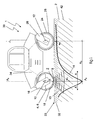
- Fig. 1 shows a representation of an embodiment of a device 1 according to the invention for compacting a bottom layer structure.
- the device 1 is designed here as a self-propelled road roller and in particular as a compactor 30. It comprises a vibrating means designed as a vibrating roller 6, which is connected via a bearing device 16 to a main body 34 of the compactor 30. Via a further bearing device 26, a static roller 24 is assigned, so that the roller train 30 via the two rollers 6, 24 is movable.
- the bottom layer structure 2 can be actively compacted in the vibrating roller 6 via driven flywheel masses.
- the vibrating roller 6 conducts load impulses P via a load introduction region 8, which essentially corresponds to the contact surface between the vibrating bandage 18 of the vibrating roller 6 and the surface 33 of the uppermost layer 32 of the bottom layer structure 2, into the ground.
- load pulses P and causing subsidence are in Fig. 1 represented by the concentric circles 15.
- a stiffness modulus Via the load pulses P introduced at the vibrating bandage 18 or vibration roller 6, which act as compaction or deformation forces in the bottom layer structure 2, a stiffness modulus can be determined, as is known from the prior art.
- This stiffness modulus corresponds to the equivalent module, ie an average stiffness value over the entire measuring depth of the bottom layer structure 2.
- both the layer E modulus of the uppermost layer 32 and the underlying bedding layers 42 have an influence on this equivalent module.
- the detection of the first value w 1 of the depression depression 14 required for determining the equivalent module takes place via a first detection means 10, which in this embodiment is arranged on the vibration roller 6 or its bearing device 16 and is statically coupled.
- a second detection means 12 is arranged, via which a second detection value E 2 of the depression trough 14 can be determined, outside of the load introduction area 8 Fig. 1 It can be seen that the second detection means 12 is spaced from the first detection means 10 and the load introduction region 8 in such a way that it is possible to detect an E-modulus of the layers arranged below the uppermost layer 32 and in particular of the bedding layer 42. Due to the distance A, D, between the first detecting means 10 or the load introduction region 8 and the second detection means 12, the deformations at the detection site of the second value W 2 are substantially determined by the ground and not on the asphalt layer itself. As an advantageous distance value A D has here a value of 1 m to 2.6 m, especially 1.8m exposed.
- detection means can be carried out according to the invention a load application P with a frequency of 30 to 50 load entries per second.
- a corresponding influence on the vibration means 4 or the vibration roller 6 can be taken here.
- the load pulse P can be regulated to a value of 50 kN via the control means, which essentially corresponds to the wheel load of a truck and thus permits a meaningful analysis of the load capacity of the bottom layer structure 2 and in particular the top layer 32.
- the device 1 according to the invention or the compactor 30 in such a way that it permits a reliable and reproducible examination of the bottom layer structure 2 and in particular of the uppermost soil layer 32.
- Fig. 2 shows a schematic representation of the device 1 according to Fig. 1 with particular attention being paid to the first and second detection devices 10 and 12.
- a geophone 11 of the first detection means 10 is arranged so as to allow detection of the reflection waves caused by the load pulses P.
- the dynamic soil stiffness of the bottom layer structure 2 lying in the load introduction region 8 can be detected via the geophone 11 or the first detection means 10.
- This dynamic soil stiffness can then be concluded in a known manner conclusions on the degree of compaction of the bottom layer structure 2.
- a geophone 13 of the second detection means 12 is also arranged on the static roller 24 of the device 1. Since the static roller 24 does not initiate its own load pulses into the bottom layer structure 2, this geophone allows detection of a stiffness value dependent on the load introduction in the load introduction region 8, which is essentially due to the distance A D between the two detection means 10 and 12 or geophones 11 and 13 depends only on the bedding layer 42 and not the upper layer 32. As a result of the value W 2 of the depression curve 14 detected by the geophone 13 or the second detection means 12, the soil stiffness and, in particular, a bedding module without the influence of the upper layer 32 can be determined.
- the first and second values W 1, W 2 determined by the two geophones 11, 13 are transmitted as measurement results to an evaluation unit 36, which compares the two detected first and second values W 1 and W 2 or from the equivalent and Bedding modules a layer E-modulus of the top layer 32 determined.
- the values thus obtained can then either be output to the operating personnel via a display unit 38 or directly influence the machine control of the device 1.
- a calibration element 40 is provided, via which, for example, the load pulses P introduced into the bottom layer structure 2 can be fixed to a defined value and in particular, for example, to a value of 50 kN.
- the vibration rate and thus the number of load pulses per second is preferably adjustable to a value between 20 and 50 times per second via such a calibration element 40.
Landscapes
- Engineering & Computer Science (AREA)
- Structural Engineering (AREA)
- Life Sciences & Earth Sciences (AREA)
- Civil Engineering (AREA)
- General Life Sciences & Earth Sciences (AREA)
- Soil Sciences (AREA)
- Mining & Mineral Resources (AREA)
- Paleontology (AREA)
- General Engineering & Computer Science (AREA)
- Architecture (AREA)
- Agronomy & Crop Science (AREA)
- Environmental & Geological Engineering (AREA)
- Chemical & Material Sciences (AREA)
- Analytical Chemistry (AREA)
- Investigation Of Foundation Soil And Reinforcement Of Foundation Soil By Compacting Or Drainage (AREA)
- Road Paving Machines (AREA)
- Investigating Strength Of Materials By Application Of Mechanical Stress (AREA)
Applications Claiming Priority (1)
| Application Number | Priority Date | Filing Date | Title |
|---|---|---|---|
| DE102010052713A DE102010052713A1 (de) | 2010-11-26 | 2010-11-26 | Verfahrbare Vorrichtung zur Verdichtung eines Bodenschichtaufbaus und Verfahren zur Ermittlung eines Schicht-E-Moduls einer obersten Schicht dieses Bodenschichtaufbaus |
Publications (3)
| Publication Number | Publication Date |
|---|---|
| EP2458088A2 true EP2458088A2 (fr) | 2012-05-30 |
| EP2458088A3 EP2458088A3 (fr) | 2016-10-05 |
| EP2458088B1 EP2458088B1 (fr) | 2018-02-21 |
Family
ID=44759382
Family Applications (1)
| Application Number | Title | Priority Date | Filing Date |
|---|---|---|---|
| EP11008033.0A Active EP2458088B1 (fr) | 2010-11-26 | 2011-10-04 | Dispositif déplaçable pour la solidification d'une structure en couches de sol et procédé de la détermination d'un module d'Young à couche d'une couche supérieure de ladite structure en couches de sol |
Country Status (4)
| Country | Link |
|---|---|
| US (1) | US8671760B2 (fr) |
| EP (1) | EP2458088B1 (fr) |
| CN (1) | CN102535313B (fr) |
| DE (1) | DE102010052713A1 (fr) |
Cited By (3)
| Publication number | Priority date | Publication date | Assignee | Title |
|---|---|---|---|---|
| CN103669179A (zh) * | 2013-11-30 | 2014-03-26 | 江苏蛟龙重工集团有限公司 | 一种路面夯实车 |
| CN104297049A (zh) * | 2014-11-10 | 2015-01-21 | 西南石油大学 | 考虑钻柱动态振动的页岩破碎实验装置及实验方法 |
| CN105324534B (zh) * | 2013-06-28 | 2017-03-08 | 卡特彼勒路面机械公司 | 基于材料压实度修改压实作用力的振动压实机 |
Families Citing this family (72)
| Publication number | Priority date | Publication date | Assignee | Title |
|---|---|---|---|---|
| AU2010362535B2 (en) * | 2010-10-13 | 2015-05-07 | Ammann Schweiz Ag | Method for determining the stiffness and/or damping of a body |
| DE102011088567A1 (de) * | 2011-12-14 | 2013-06-20 | Hamm Ag | Vorrichtung zur Erfassung der Bewegung einer Verdichterwalze eines Bodenverdichters |
| CN104364445A (zh) * | 2012-04-06 | 2015-02-18 | 俄克拉何马大学董事会 | 用于测定道路硬度的方法和设备 |
| US9650062B2 (en) | 2013-08-26 | 2017-05-16 | Wacker Neuson Production Americas Llc | System for controlling remote operation of ground working devices |
| DE102014008116A1 (de) | 2014-06-03 | 2015-12-03 | Bomag Gmbh | Verfahren zur schmiermittelversorgung eines getriebes, getriebeschmiereinrichtung, getriebeeinheit und baumaschine |
| US9534995B2 (en) * | 2014-06-11 | 2017-01-03 | Caterpillar Paving Products Inc. | System and method for determining a modulus of resilience |
| US9845580B2 (en) | 2016-04-25 | 2017-12-19 | Caterpillar Paving Products Inc. | Compaction system including articulated joint force measurement |
| CN107059572B (zh) * | 2017-02-13 | 2019-01-15 | 嘉兴钛胺新材料科技有限公司 | 一种道路建设用土壤平整单元 |
| WO2018157091A1 (fr) | 2017-02-24 | 2018-08-30 | Brigham Young University | Éléments de contact d'excitation acoustique fixés par l'intermédiaire d'un matériau élastique |
| DE102017006844B4 (de) | 2017-07-18 | 2019-04-11 | Bomag Gmbh | Bodenverdichter und Verfahren zur Bestimmung von Untergrundeigenschaften mittels eines Bodenverdichters |
| US20190170569A1 (en) * | 2017-12-06 | 2019-06-06 | Caterpillar Paving Products Inc. | Vibration monitoring system |
| US11589509B2 (en) | 2018-10-26 | 2023-02-28 | Deere & Company | Predictive machine characteristic map generation and control system |
| US11957072B2 (en) | 2020-02-06 | 2024-04-16 | Deere & Company | Pre-emergence weed detection and mitigation system |
| US11467605B2 (en) | 2019-04-10 | 2022-10-11 | Deere & Company | Zonal machine control |
| US11079725B2 (en) | 2019-04-10 | 2021-08-03 | Deere & Company | Machine control using real-time model |
| US11641800B2 (en) | 2020-02-06 | 2023-05-09 | Deere & Company | Agricultural harvesting machine with pre-emergence weed detection and mitigation system |
| US11653588B2 (en) | 2018-10-26 | 2023-05-23 | Deere & Company | Yield map generation and control system |
| US11240961B2 (en) | 2018-10-26 | 2022-02-08 | Deere & Company | Controlling a harvesting machine based on a geo-spatial representation indicating where the harvesting machine is likely to reach capacity |
| US11178818B2 (en) | 2018-10-26 | 2021-11-23 | Deere & Company | Harvesting machine control system with fill level processing based on yield data |
| US12069978B2 (en) | 2018-10-26 | 2024-08-27 | Deere & Company | Predictive environmental characteristic map generation and control system |
| US11672203B2 (en) | 2018-10-26 | 2023-06-13 | Deere & Company | Predictive map generation and control |
| US11460385B2 (en) | 2019-02-11 | 2022-10-04 | Ingios Geotechnics, Inc. | Compaction control system for and methods of accurately determining properties of compacted and/or existing ground materials |
| US11234366B2 (en) | 2019-04-10 | 2022-02-01 | Deere & Company | Image selection for machine control |
| US11778945B2 (en) | 2019-04-10 | 2023-10-10 | Deere & Company | Machine control using real-time model |
| US12329148B2 (en) | 2020-02-06 | 2025-06-17 | Deere & Company | Predictive weed map and material application machine control |
| US12035648B2 (en) | 2020-02-06 | 2024-07-16 | Deere & Company | Predictive weed map generation and control system |
| US12225846B2 (en) | 2020-02-06 | 2025-02-18 | Deere & Company | Machine control using a predictive map |
| US11477940B2 (en) | 2020-03-26 | 2022-10-25 | Deere & Company | Mobile work machine control based on zone parameter modification |
| CN111472243B (zh) * | 2020-04-22 | 2021-12-10 | 重庆交通大学 | 一种路基路面结构综合动态模量的测试方法 |
| US12178158B2 (en) | 2020-10-09 | 2024-12-31 | Deere & Company | Predictive map generation and control system for an agricultural work machine |
| US12386354B2 (en) | 2020-10-09 | 2025-08-12 | Deere & Company | Predictive power map generation and control system |
| US12550802B2 (en) | 2020-10-08 | 2026-02-17 | Deere & Company | Predictive machine characteristic map generation and control system |
| US12419220B2 (en) | 2020-10-09 | 2025-09-23 | Deere & Company | Predictive map generation and control system |
| US11849672B2 (en) | 2020-10-09 | 2023-12-26 | Deere & Company | Machine control using a predictive map |
| US11927459B2 (en) | 2020-10-09 | 2024-03-12 | Deere & Company | Machine control using a predictive map |
| US11983009B2 (en) | 2020-10-09 | 2024-05-14 | Deere & Company | Map generation and control system |
| US11675354B2 (en) | 2020-10-09 | 2023-06-13 | Deere & Company | Machine control using a predictive map |
| US11864483B2 (en) | 2020-10-09 | 2024-01-09 | Deere & Company | Predictive map generation and control system |
| US11592822B2 (en) | 2020-10-09 | 2023-02-28 | Deere & Company | Machine control using a predictive map |
| US11874669B2 (en) | 2020-10-09 | 2024-01-16 | Deere & Company | Map generation and control system |
| US11635765B2 (en) | 2020-10-09 | 2023-04-25 | Deere & Company | Crop state map generation and control system |
| US11889788B2 (en) | 2020-10-09 | 2024-02-06 | Deere & Company | Predictive biomass map generation and control |
| US11650587B2 (en) | 2020-10-09 | 2023-05-16 | Deere & Company | Predictive power map generation and control system |
| US11871697B2 (en) | 2020-10-09 | 2024-01-16 | Deere & Company | Crop moisture map generation and control system |
| US11895948B2 (en) | 2020-10-09 | 2024-02-13 | Deere & Company | Predictive map generation and control based on soil properties |
| US12069986B2 (en) | 2020-10-09 | 2024-08-27 | Deere & Company | Map generation and control system |
| US11825768B2 (en) | 2020-10-09 | 2023-11-28 | Deere & Company | Machine control using a predictive map |
| US11711995B2 (en) | 2020-10-09 | 2023-08-01 | Deere & Company | Machine control using a predictive map |
| US11727680B2 (en) | 2020-10-09 | 2023-08-15 | Deere & Company | Predictive map generation based on seeding characteristics and control |
| US12422847B2 (en) | 2020-10-09 | 2025-09-23 | Deere & Company | Predictive agricultural model and map generation |
| US11474523B2 (en) | 2020-10-09 | 2022-10-18 | Deere & Company | Machine control using a predictive speed map |
| US11844311B2 (en) | 2020-10-09 | 2023-12-19 | Deere & Company | Machine control using a predictive map |
| US11946747B2 (en) | 2020-10-09 | 2024-04-02 | Deere & Company | Crop constituent map generation and control system |
| US11849671B2 (en) | 2020-10-09 | 2023-12-26 | Deere & Company | Crop state map generation and control system |
| US11845449B2 (en) | 2020-10-09 | 2023-12-19 | Deere & Company | Map generation and control system |
| US12013245B2 (en) | 2020-10-09 | 2024-06-18 | Deere & Company | Predictive map generation and control system |
| US20220110238A1 (en) | 2020-10-09 | 2022-04-14 | Deere & Company | Machine control using a predictive map |
| US11889787B2 (en) | 2020-10-09 | 2024-02-06 | Deere & Company | Predictive speed map generation and control system |
| US12250905B2 (en) | 2020-10-09 | 2025-03-18 | Deere & Company | Machine control using a predictive map |
| US12127500B2 (en) | 2021-01-27 | 2024-10-29 | Deere & Company | Machine control using a map with regime zones |
| US12310286B2 (en) | 2021-12-14 | 2025-05-27 | Deere & Company | Crop constituent sensing |
| US12302791B2 (en) | 2021-12-20 | 2025-05-20 | Deere & Company | Crop constituents, predictive mapping, and agricultural harvester control |
| US12245549B2 (en) | 2022-01-11 | 2025-03-11 | Deere & Company | Predictive response map generation and control system |
| US12082531B2 (en) | 2022-01-26 | 2024-09-10 | Deere & Company | Systems and methods for predicting material dynamics |
| US12520759B2 (en) | 2022-01-26 | 2026-01-13 | Deere & Company | Systems and methods for predicting material dynamics |
| CN114674737B (zh) * | 2022-04-02 | 2023-06-16 | 西南交通大学 | 路基填料压实特性分析装置及其方法 |
| US12295288B2 (en) | 2022-04-05 | 2025-05-13 | Deere &Company | Predictive machine setting map generation and control system |
| US12358493B2 (en) | 2022-04-08 | 2025-07-15 | Deere & Company | Systems and methods for predictive power requirements and control |
| US12582035B2 (en) | 2022-04-08 | 2026-03-24 | Deere & Company | Systems and methods for predictive power requirements and control |
| US12284934B2 (en) | 2022-04-08 | 2025-04-29 | Deere & Company | Systems and methods for predictive tractive characteristics and control |
| US12058951B2 (en) | 2022-04-08 | 2024-08-13 | Deere & Company | Predictive nutrient map and control |
| US12298767B2 (en) | 2022-04-08 | 2025-05-13 | Deere & Company | Predictive material consumption map and control |
Family Cites Families (17)
| Publication number | Priority date | Publication date | Assignee | Title |
|---|---|---|---|---|
| US3553903A (en) * | 1967-07-31 | 1971-01-12 | Goodyear Tire & Rubber | Control system for a tire grinding machine |
| SE401736B (sv) * | 1976-08-18 | 1978-05-22 | Konsult Och Utveckling Ab Kuab | Apparat for anbringande av en belastning och uppmetning av sambandet mellan belastningen och deformationen |
| US5025150A (en) * | 1988-10-14 | 1991-06-18 | Mk-Ferguson Company | Site survey method and apparatus |
| DE19529115A1 (de) * | 1995-08-08 | 1997-03-06 | Wacker Werke Kg | Vibrationsmechanismus, insbesondere zur Verwendung zur Verdichtung von Böden |
| US5719338A (en) * | 1995-10-24 | 1998-02-17 | Ingersoll-Rand Company | Method and apparatus for providing an indication of compaction in a vibration compaction vehicle |
| WO1998017865A1 (fr) * | 1996-10-21 | 1998-04-30 | Ammann Verdichtung Ag | Procede pour mesurer des grandeurs mecaniques d'un sol et de compactage dudit sol, et dispositif de mesure ou de compactage de sol |
| US5952561A (en) * | 1997-03-19 | 1999-09-14 | Iowa State University Research Foundation, Inc. | Real time asphalt pavement quality sensor using a differential approach |
| CN2302499Y (zh) * | 1997-05-05 | 1998-12-30 | 南京理工大学 | 便携式激光路面弯沉检测仪 |
| US6244102B1 (en) * | 1998-09-18 | 2001-06-12 | Dynasens Ltd. | Method and system for examination and optimal compaction of soil enbankments |
| CN2364456Y (zh) * | 1999-03-12 | 2000-02-16 | 哈尔滨东北道路研究所 | 道路压实智能检测仪 |
| DE19956943B4 (de) | 1999-11-26 | 2020-03-19 | Bomag Gmbh | Vorrichtung zur Kontrolle der Verdichtung bei Vibrationsverdichtungsgeräten |
| CN1332098A (zh) * | 2001-07-06 | 2002-01-23 | 杨济安 | 车载压实度检测装置 |
| CN1152260C (zh) * | 2001-12-19 | 2004-06-02 | 河北工业大学 | 智能化道路机载压实检测仪 |
| EP1516961B1 (fr) * | 2003-09-19 | 2013-12-25 | Ammann Aufbereitung AG | Méthode de détermination de la rigidité du sol et dispositif de compactage de sol |
| CN100447337C (zh) * | 2005-06-13 | 2008-12-31 | 郑州大学 | 落锤式弯沉仪及探地雷达在道路施工过程中的应用 |
| US7938595B2 (en) * | 2007-04-30 | 2011-05-10 | Caterpillar Paving Products Inc. | Surface compactor and method of operating a surface compactor |
| EP2148005A1 (fr) * | 2008-07-24 | 2010-01-27 | Ammann Czech Republic, a.s. | Rouleau vibratoire tandem |
-
2010
- 2010-11-26 DE DE102010052713A patent/DE102010052713A1/de not_active Ceased
-
2011
- 2011-10-04 EP EP11008033.0A patent/EP2458088B1/fr active Active
- 2011-11-21 US US13/300,879 patent/US8671760B2/en not_active Expired - Fee Related
- 2011-11-25 CN CN201110378854.XA patent/CN102535313B/zh not_active Expired - Fee Related
Non-Patent Citations (1)
| Title |
|---|
| None |
Cited By (4)
| Publication number | Priority date | Publication date | Assignee | Title |
|---|---|---|---|---|
| CN105324534B (zh) * | 2013-06-28 | 2017-03-08 | 卡特彼勒路面机械公司 | 基于材料压实度修改压实作用力的振动压实机 |
| CN103669179A (zh) * | 2013-11-30 | 2014-03-26 | 江苏蛟龙重工集团有限公司 | 一种路面夯实车 |
| CN103669179B (zh) * | 2013-11-30 | 2016-04-27 | 江苏蛟龙重工集团有限公司 | 一种路面夯实车 |
| CN104297049A (zh) * | 2014-11-10 | 2015-01-21 | 西南石油大学 | 考虑钻柱动态振动的页岩破碎实验装置及实验方法 |
Also Published As
| Publication number | Publication date |
|---|---|
| EP2458088A3 (fr) | 2016-10-05 |
| CN102535313A (zh) | 2012-07-04 |
| CN102535313B (zh) | 2014-12-24 |
| DE102010052713A1 (de) | 2012-05-31 |
| US20120134746A1 (en) | 2012-05-31 |
| US8671760B2 (en) | 2014-03-18 |
| EP2458088B1 (fr) | 2018-02-21 |
Similar Documents
| Publication | Publication Date | Title |
|---|---|---|
| EP2458088B1 (fr) | Dispositif déplaçable pour la solidification d'une structure en couches de sol et procédé de la détermination d'un module d'Young à couche d'une couche supérieure de ladite structure en couches de sol | |
| DE102017006844B4 (de) | Bodenverdichter und Verfahren zur Bestimmung von Untergrundeigenschaften mittels eines Bodenverdichters | |
| EP3631087B1 (fr) | Procédé et dispositif destinés à comprimer un ballast | |
| EP1516961B1 (fr) | Méthode de détermination de la rigidité du sol et dispositif de compactage de sol | |
| EP2927372B1 (fr) | Engin automobile et procédé de commande d'un engin automobile | |
| EP3870760B1 (fr) | Procédé et machine pour stabiliser une voie ferrée | |
| EP0688902B1 (fr) | Méthode de mesure de la résistance aux déplacements latéraux des rails d'une voie ferrée | |
| EP3176324B1 (fr) | Procédé de détermination d'un état de compactage d'un sous-sol | |
| DE102015007369A1 (de) | System und verfahren zum bestimmen eines elastizitätsmoduls | |
| DE102016124875A1 (de) | Verdichtungsmessung unter Verwendung von nahegelegenen Sensoren | |
| DE102006008266B4 (de) | Verfahren und Vorrichtung zum Messen von Bodenparametern mittels Verdichtungsmaschinen | |
| EP2627826A1 (fr) | Procédé permettant de déterminer la rigidité et/ou l'amortissement d'une zone d'un corps | |
| DE102010060843A1 (de) | Verfahren und Vorrichtung zum Messen von Bodenparametern mittels Verdichtungsmaschinen | |
| WO2009124681A1 (fr) | Système de mesure de charges dans le contact roue-rail de véhicules ferroviaires | |
| DE2737099C2 (fr) | ||
| DE60303303T2 (de) | Fallgewichtverdichtung | |
| EP1182300A1 (fr) | Méthode de détermination de la sécurité sismique d'ouvrages | |
| DE102010019053A1 (de) | Bodenverdichtungsvorrichtung mit Messvorrichtung zum Bestimmen von Bodenkennwerten | |
| DE102016124106A1 (de) | Einstellung des verdichtungsaufwands unter verwendung von vibrationssensoren | |
| DE69905484T2 (de) | Verfahren und vorrichtung zur messung der tragfähigkeit eines unterbaus | |
| DE202010017338U1 (de) | Messvorrichtung zum Bestimmen vonBodenkennwerten | |
| DE3707648C2 (de) | Verfahren und Vorrichtung zum Bestimmen des Verdichtungsgrads beim Verdichten eines Untergrundes mittels einer Vibrationswalze | |
| DE60304313T2 (de) | Messung der Verdichtung von körnigen Materialschichten | |
| WO2022078698A1 (fr) | Procédé et système pour déterminer une transmission de vibrations au niveau d'une voie | |
| DE102009053297A1 (de) | Verfahren zur Bestimmung der vibrationstechnischen Eigenschaften von Unterlagsplatten in einer Umlaufanlage zur Herstellung von Betonwaren mittels Vibrationsverdichtung und Vorrichtung zur zerstörungsfreien Messung dynamischer Eigenschaften einer Unterlagsplatte |
Legal Events
| Date | Code | Title | Description |
|---|---|---|---|
| PUAI | Public reference made under article 153(3) epc to a published international application that has entered the european phase |
Free format text: ORIGINAL CODE: 0009012 |
|
| AK | Designated contracting states |
Kind code of ref document: A2 Designated state(s): AL AT BE BG CH CY CZ DE DK EE ES FI FR GB GR HR HU IE IS IT LI LT LU LV MC MK MT NL NO PL PT RO RS SE SI SK SM TR |
|
| AX | Request for extension of the european patent |
Extension state: BA ME |
|
| PUAL | Search report despatched |
Free format text: ORIGINAL CODE: 0009013 |
|
| AK | Designated contracting states |
Kind code of ref document: A3 Designated state(s): AL AT BE BG CH CY CZ DE DK EE ES FI FR GB GR HR HU IE IS IT LI LT LU LV MC MK MT NL NO PL PT RO RS SE SI SK SM TR |
|
| AX | Request for extension of the european patent |
Extension state: BA ME |
|
| RIC1 | Information provided on ipc code assigned before grant |
Ipc: E01C 19/30 20060101ALI20160830BHEP Ipc: E01C 19/28 20060101AFI20160830BHEP |
|
| 17P | Request for examination filed |
Effective date: 20170331 |
|
| RBV | Designated contracting states (corrected) |
Designated state(s): AL AT BE BG CH CY CZ DE DK EE ES FI FR GB GR HR HU IE IS IT LI LT LU LV MC MK MT NL NO PL PT RO RS SE SI SK SM TR |
|
| GRAP | Despatch of communication of intention to grant a patent |
Free format text: ORIGINAL CODE: EPIDOSNIGR1 |
|
| INTG | Intention to grant announced |
Effective date: 20170929 |
|
| GRAS | Grant fee paid |
Free format text: ORIGINAL CODE: EPIDOSNIGR3 |
|
| GRAA | (expected) grant |
Free format text: ORIGINAL CODE: 0009210 |
|
| AK | Designated contracting states |
Kind code of ref document: B1 Designated state(s): AL AT BE BG CH CY CZ DE DK EE ES FI FR GB GR HR HU IE IS IT LI LT LU LV MC MK MT NL NO PL PT RO RS SE SI SK SM TR |
|
| REG | Reference to a national code |
Ref country code: GB Ref legal event code: FG4D Free format text: NOT ENGLISH |
|
| REG | Reference to a national code |
Ref country code: CH Ref legal event code: EP |
|
| REG | Reference to a national code |
Ref country code: AT Ref legal event code: REF Ref document number: 971855 Country of ref document: AT Kind code of ref document: T Effective date: 20180315 |
|
| REG | Reference to a national code |
Ref country code: IE Ref legal event code: FG4D Free format text: LANGUAGE OF EP DOCUMENT: GERMAN |
|
| REG | Reference to a national code |
Ref country code: DE Ref legal event code: R096 Ref document number: 502011013738 Country of ref document: DE |
|
| REG | Reference to a national code |
Ref country code: CH Ref legal event code: NV Representative=s name: HEPP WENGER RYFFEL AG, CH |
|
| REG | Reference to a national code |
Ref country code: NL Ref legal event code: MP Effective date: 20180221 |
|
| REG | Reference to a national code |
Ref country code: LT Ref legal event code: MG4D |
|
| PG25 | Lapsed in a contracting state [announced via postgrant information from national office to epo] |
Ref country code: ES Free format text: LAPSE BECAUSE OF FAILURE TO SUBMIT A TRANSLATION OF THE DESCRIPTION OR TO PAY THE FEE WITHIN THE PRESCRIBED TIME-LIMIT Effective date: 20180221 Ref country code: CY Free format text: LAPSE BECAUSE OF FAILURE TO SUBMIT A TRANSLATION OF THE DESCRIPTION OR TO PAY THE FEE WITHIN THE PRESCRIBED TIME-LIMIT Effective date: 20180221 Ref country code: LT Free format text: LAPSE BECAUSE OF FAILURE TO SUBMIT A TRANSLATION OF THE DESCRIPTION OR TO PAY THE FEE WITHIN THE PRESCRIBED TIME-LIMIT Effective date: 20180221 Ref country code: NL Free format text: LAPSE BECAUSE OF FAILURE TO SUBMIT A TRANSLATION OF THE DESCRIPTION OR TO PAY THE FEE WITHIN THE PRESCRIBED TIME-LIMIT Effective date: 20180221 Ref country code: FI Free format text: LAPSE BECAUSE OF FAILURE TO SUBMIT A TRANSLATION OF THE DESCRIPTION OR TO PAY THE FEE WITHIN THE PRESCRIBED TIME-LIMIT Effective date: 20180221 Ref country code: HR Free format text: LAPSE BECAUSE OF FAILURE TO SUBMIT A TRANSLATION OF THE DESCRIPTION OR TO PAY THE FEE WITHIN THE PRESCRIBED TIME-LIMIT Effective date: 20180221 Ref country code: NO Free format text: LAPSE BECAUSE OF FAILURE TO SUBMIT A TRANSLATION OF THE DESCRIPTION OR TO PAY THE FEE WITHIN THE PRESCRIBED TIME-LIMIT Effective date: 20180521 |
|
| PG25 | Lapsed in a contracting state [announced via postgrant information from national office to epo] |
Ref country code: GR Free format text: LAPSE BECAUSE OF FAILURE TO SUBMIT A TRANSLATION OF THE DESCRIPTION OR TO PAY THE FEE WITHIN THE PRESCRIBED TIME-LIMIT Effective date: 20180522 Ref country code: RS Free format text: LAPSE BECAUSE OF FAILURE TO SUBMIT A TRANSLATION OF THE DESCRIPTION OR TO PAY THE FEE WITHIN THE PRESCRIBED TIME-LIMIT Effective date: 20180221 Ref country code: LV Free format text: LAPSE BECAUSE OF FAILURE TO SUBMIT A TRANSLATION OF THE DESCRIPTION OR TO PAY THE FEE WITHIN THE PRESCRIBED TIME-LIMIT Effective date: 20180221 Ref country code: SE Free format text: LAPSE BECAUSE OF FAILURE TO SUBMIT A TRANSLATION OF THE DESCRIPTION OR TO PAY THE FEE WITHIN THE PRESCRIBED TIME-LIMIT Effective date: 20180221 |
|
| PG25 | Lapsed in a contracting state [announced via postgrant information from national office to epo] |
Ref country code: MT Free format text: LAPSE BECAUSE OF FAILURE TO SUBMIT A TRANSLATION OF THE DESCRIPTION OR TO PAY THE FEE WITHIN THE PRESCRIBED TIME-LIMIT Effective date: 20180221 |
|
| REG | Reference to a national code |
Ref country code: FR Ref legal event code: PLFP Year of fee payment: 8 |
|
| PG25 | Lapsed in a contracting state [announced via postgrant information from national office to epo] |
Ref country code: RO Free format text: LAPSE BECAUSE OF FAILURE TO SUBMIT A TRANSLATION OF THE DESCRIPTION OR TO PAY THE FEE WITHIN THE PRESCRIBED TIME-LIMIT Effective date: 20180221 Ref country code: AL Free format text: LAPSE BECAUSE OF FAILURE TO SUBMIT A TRANSLATION OF THE DESCRIPTION OR TO PAY THE FEE WITHIN THE PRESCRIBED TIME-LIMIT Effective date: 20180221 Ref country code: PL Free format text: LAPSE BECAUSE OF FAILURE TO SUBMIT A TRANSLATION OF THE DESCRIPTION OR TO PAY THE FEE WITHIN THE PRESCRIBED TIME-LIMIT Effective date: 20180221 Ref country code: EE Free format text: LAPSE BECAUSE OF FAILURE TO SUBMIT A TRANSLATION OF THE DESCRIPTION OR TO PAY THE FEE WITHIN THE PRESCRIBED TIME-LIMIT Effective date: 20180221 Ref country code: IT Free format text: LAPSE BECAUSE OF FAILURE TO SUBMIT A TRANSLATION OF THE DESCRIPTION OR TO PAY THE FEE WITHIN THE PRESCRIBED TIME-LIMIT Effective date: 20180221 |
|
| REG | Reference to a national code |
Ref country code: DE Ref legal event code: R097 Ref document number: 502011013738 Country of ref document: DE |
|
| PG25 | Lapsed in a contracting state [announced via postgrant information from national office to epo] |
Ref country code: DK Free format text: LAPSE BECAUSE OF FAILURE TO SUBMIT A TRANSLATION OF THE DESCRIPTION OR TO PAY THE FEE WITHIN THE PRESCRIBED TIME-LIMIT Effective date: 20180221 Ref country code: SM Free format text: LAPSE BECAUSE OF FAILURE TO SUBMIT A TRANSLATION OF THE DESCRIPTION OR TO PAY THE FEE WITHIN THE PRESCRIBED TIME-LIMIT Effective date: 20180221 Ref country code: SK Free format text: LAPSE BECAUSE OF FAILURE TO SUBMIT A TRANSLATION OF THE DESCRIPTION OR TO PAY THE FEE WITHIN THE PRESCRIBED TIME-LIMIT Effective date: 20180221 |
|
| PLBE | No opposition filed within time limit |
Free format text: ORIGINAL CODE: 0009261 |
|
| STAA | Information on the status of an ep patent application or granted ep patent |
Free format text: STATUS: NO OPPOSITION FILED WITHIN TIME LIMIT |
|
| 26N | No opposition filed |
Effective date: 20181122 |
|
| PG25 | Lapsed in a contracting state [announced via postgrant information from national office to epo] |
Ref country code: SI Free format text: LAPSE BECAUSE OF FAILURE TO SUBMIT A TRANSLATION OF THE DESCRIPTION OR TO PAY THE FEE WITHIN THE PRESCRIBED TIME-LIMIT Effective date: 20180221 |
|
| REG | Reference to a national code |
Ref country code: BE Ref legal event code: MM Effective date: 20181031 |
|
| PG25 | Lapsed in a contracting state [announced via postgrant information from national office to epo] |
Ref country code: MC Free format text: LAPSE BECAUSE OF FAILURE TO SUBMIT A TRANSLATION OF THE DESCRIPTION OR TO PAY THE FEE WITHIN THE PRESCRIBED TIME-LIMIT Effective date: 20180221 Ref country code: LU Free format text: LAPSE BECAUSE OF NON-PAYMENT OF DUE FEES Effective date: 20181004 |
|
| REG | Reference to a national code |
Ref country code: IE Ref legal event code: MM4A |
|
| PG25 | Lapsed in a contracting state [announced via postgrant information from national office to epo] |
Ref country code: BE Free format text: LAPSE BECAUSE OF NON-PAYMENT OF DUE FEES Effective date: 20181031 |
|
| PG25 | Lapsed in a contracting state [announced via postgrant information from national office to epo] |
Ref country code: IE Free format text: LAPSE BECAUSE OF NON-PAYMENT OF DUE FEES Effective date: 20181004 |
|
| REG | Reference to a national code |
Ref country code: AT Ref legal event code: MM01 Ref document number: 971855 Country of ref document: AT Kind code of ref document: T Effective date: 20181004 |
|
| PG25 | Lapsed in a contracting state [announced via postgrant information from national office to epo] |
Ref country code: AT Free format text: LAPSE BECAUSE OF NON-PAYMENT OF DUE FEES Effective date: 20181004 |
|
| PG25 | Lapsed in a contracting state [announced via postgrant information from national office to epo] |
Ref country code: TR Free format text: LAPSE BECAUSE OF FAILURE TO SUBMIT A TRANSLATION OF THE DESCRIPTION OR TO PAY THE FEE WITHIN THE PRESCRIBED TIME-LIMIT Effective date: 20180221 |
|
| PG25 | Lapsed in a contracting state [announced via postgrant information from national office to epo] |
Ref country code: PT Free format text: LAPSE BECAUSE OF FAILURE TO SUBMIT A TRANSLATION OF THE DESCRIPTION OR TO PAY THE FEE WITHIN THE PRESCRIBED TIME-LIMIT Effective date: 20180221 |
|
| PG25 | Lapsed in a contracting state [announced via postgrant information from national office to epo] |
Ref country code: MK Free format text: LAPSE BECAUSE OF NON-PAYMENT OF DUE FEES Effective date: 20180221 Ref country code: HU Free format text: LAPSE BECAUSE OF FAILURE TO SUBMIT A TRANSLATION OF THE DESCRIPTION OR TO PAY THE FEE WITHIN THE PRESCRIBED TIME-LIMIT; INVALID AB INITIO Effective date: 20111004 |
|
| PG25 | Lapsed in a contracting state [announced via postgrant information from national office to epo] |
Ref country code: IS Free format text: LAPSE BECAUSE OF FAILURE TO SUBMIT A TRANSLATION OF THE DESCRIPTION OR TO PAY THE FEE WITHIN THE PRESCRIBED TIME-LIMIT Effective date: 20180621 |
|
| P01 | Opt-out of the competence of the unified patent court (upc) registered |
Effective date: 20230527 |
|
| REG | Reference to a national code |
Ref country code: DE Ref legal event code: R082 Ref document number: 502011013738 Country of ref document: DE Representative=s name: ZIMMERMANN & PARTNER PATENTANWAELTE MBB, DE |
|
| PGFP | Annual fee paid to national office [announced via postgrant information from national office to epo] |
Ref country code: CZ Payment date: 20230922 Year of fee payment: 13 |
|
| PGFP | Annual fee paid to national office [announced via postgrant information from national office to epo] |
Ref country code: GB Payment date: 20231025 Year of fee payment: 13 |
|
| PGFP | Annual fee paid to national office [announced via postgrant information from national office to epo] |
Ref country code: FR Payment date: 20231023 Year of fee payment: 13 Ref country code: DE Payment date: 20231018 Year of fee payment: 13 Ref country code: CH Payment date: 20231101 Year of fee payment: 13 Ref country code: BG Payment date: 20231019 Year of fee payment: 13 |
|
| PG25 | Lapsed in a contracting state [announced via postgrant information from national office to epo] |
Ref country code: CZ Free format text: LAPSE BECAUSE OF NON-PAYMENT OF DUE FEES Effective date: 20241004 |
|
| REG | Reference to a national code |
Ref country code: DE Ref legal event code: R119 Ref document number: 502011013738 Country of ref document: DE |
|
| REG | Reference to a national code |
Ref country code: CH Ref legal event code: PL |
|
| GBPC | Gb: european patent ceased through non-payment of renewal fee |
Effective date: 20241004 |
|
| PG25 | Lapsed in a contracting state [announced via postgrant information from national office to epo] |
Ref country code: DE Free format text: LAPSE BECAUSE OF NON-PAYMENT OF DUE FEES Effective date: 20250501 |
|
| PG25 | Lapsed in a contracting state [announced via postgrant information from national office to epo] |
Ref country code: GB Free format text: LAPSE BECAUSE OF NON-PAYMENT OF DUE FEES Effective date: 20241004 |
|
| PG25 | Lapsed in a contracting state [announced via postgrant information from national office to epo] |
Ref country code: FR Free format text: LAPSE BECAUSE OF NON-PAYMENT OF DUE FEES Effective date: 20241031 |
|
| PG25 | Lapsed in a contracting state [announced via postgrant information from national office to epo] |
Ref country code: BG Free format text: LAPSE BECAUSE OF NON-PAYMENT OF DUE FEES Effective date: 20241004 |
|
| PG25 | Lapsed in a contracting state [announced via postgrant information from national office to epo] |
Ref country code: CH Free format text: LAPSE BECAUSE OF NON-PAYMENT OF DUE FEES Effective date: 20241031 |