EP2927372B1 - Engin automobile et procédé de commande d'un engin automobile - Google Patents
Engin automobile et procédé de commande d'un engin automobile Download PDFInfo
- Publication number
- EP2927372B1 EP2927372B1 EP15160925.2A EP15160925A EP2927372B1 EP 2927372 B1 EP2927372 B1 EP 2927372B1 EP 15160925 A EP15160925 A EP 15160925A EP 2927372 B1 EP2927372 B1 EP 2927372B1
- Authority
- EP
- European Patent Office
- Prior art keywords
- ground
- machine frame
- lifting
- distance
- construction machine
- Prior art date
- Legal status (The legal status is an assumption and is not a legal conclusion. Google has not performed a legal analysis and makes no representation as to the accuracy of the status listed.)
- Active
Links
Images



Classifications
-
- E—FIXED CONSTRUCTIONS
- E01—CONSTRUCTION OF ROADS, RAILWAYS, OR BRIDGES
- E01C—CONSTRUCTION OF, OR SURFACES FOR, ROADS, SPORTS GROUNDS, OR THE LIKE; MACHINES OR AUXILIARY TOOLS FOR CONSTRUCTION OR REPAIR
- E01C19/00—Machines, tools or auxiliary devices for preparing or distributing paving materials, for working the placed materials, or for forming, consolidating, or finishing the paving
- E01C19/48—Machines, tools or auxiliary devices for preparing or distributing paving materials, for working the placed materials, or for forming, consolidating, or finishing the paving for laying-down the materials and consolidating them, or finishing the surface, e.g. slip forms therefor, forming kerbs or gutters in a continuous operation in situ
- E01C19/4886—Machines, tools or auxiliary devices for preparing or distributing paving materials, for working the placed materials, or for forming, consolidating, or finishing the paving for laying-down the materials and consolidating them, or finishing the surface, e.g. slip forms therefor, forming kerbs or gutters in a continuous operation in situ for forming in a continuous operation kerbs, gutters, berms, safety kerbs, median barriers or like structures in situ, e.g. by slip-forming, by extrusion
- E01C19/4893—Apparatus designed for railless operation
-
- B—PERFORMING OPERATIONS; TRANSPORTING
- B62—LAND VEHICLES FOR TRAVELLING OTHERWISE THAN ON RAILS
- B62D—MOTOR VEHICLES; TRAILERS
- B62D55/00—Endless track vehicles
- B62D55/08—Endless track units; Parts thereof
- B62D55/104—Suspension devices for wheels, rollers, bogies or frames
- B62D55/116—Attitude or position control of chassis by action on suspension, e.g. to compensate for a slope
-
- E—FIXED CONSTRUCTIONS
- E01—CONSTRUCTION OF ROADS, RAILWAYS, OR BRIDGES
- E01C—CONSTRUCTION OF, OR SURFACES FOR, ROADS, SPORTS GROUNDS, OR THE LIKE; MACHINES OR AUXILIARY TOOLS FOR CONSTRUCTION OR REPAIR
- E01C19/00—Machines, tools or auxiliary devices for preparing or distributing paving materials, for working the placed materials, or for forming, consolidating, or finishing the paving
- E01C19/48—Machines, tools or auxiliary devices for preparing or distributing paving materials, for working the placed materials, or for forming, consolidating, or finishing the paving for laying-down the materials and consolidating them, or finishing the surface, e.g. slip forms therefor, forming kerbs or gutters in a continuous operation in situ
-
- E—FIXED CONSTRUCTIONS
- E01—CONSTRUCTION OF ROADS, RAILWAYS, OR BRIDGES
- E01C—CONSTRUCTION OF, OR SURFACES FOR, ROADS, SPORTS GROUNDS, OR THE LIKE; MACHINES OR AUXILIARY TOOLS FOR CONSTRUCTION OR REPAIR
- E01C23/00—Auxiliary devices or arrangements for constructing, repairing, reconditioning, or taking-up road or like surfaces
- E01C23/06—Devices or arrangements for working the finished surface; Devices for repairing or reconditioning the surface of damaged paving; Recycling in place or on the road
- E01C23/07—Apparatus combining measurement of the surface configuration of paving with application of material in proportion to the measured irregularities
-
- E—FIXED CONSTRUCTIONS
- E01—CONSTRUCTION OF ROADS, RAILWAYS, OR BRIDGES
- E01C—CONSTRUCTION OF, OR SURFACES FOR, ROADS, SPORTS GROUNDS, OR THE LIKE; MACHINES OR AUXILIARY TOOLS FOR CONSTRUCTION OR REPAIR
- E01C23/00—Auxiliary devices or arrangements for constructing, repairing, reconditioning, or taking-up road or like surfaces
- E01C23/06—Devices or arrangements for working the finished surface; Devices for repairing or reconditioning the surface of damaged paving; Recycling in place or on the road
- E01C23/08—Devices or arrangements for working the finished surface; Devices for repairing or reconditioning the surface of damaged paving; Recycling in place or on the road for roughening or patterning; for removing the surface down to a predetermined depth high spots or material bonded to the surface, e.g. markings; for maintaining earth roads, clay courts or like surfaces by means of surface working tools, e.g. scarifiers, levelling blades
- E01C23/085—Devices or arrangements for working the finished surface; Devices for repairing or reconditioning the surface of damaged paving; Recycling in place or on the road for roughening or patterning; for removing the surface down to a predetermined depth high spots or material bonded to the surface, e.g. markings; for maintaining earth roads, clay courts or like surfaces by means of surface working tools, e.g. scarifiers, levelling blades using power-driven tools, e.g. vibratory tools
- E01C23/088—Rotary tools, e.g. milling drums
-
- E—FIXED CONSTRUCTIONS
- E01—CONSTRUCTION OF ROADS, RAILWAYS, OR BRIDGES
- E01C—CONSTRUCTION OF, OR SURFACES FOR, ROADS, SPORTS GROUNDS, OR THE LIKE; MACHINES OR AUXILIARY TOOLS FOR CONSTRUCTION OR REPAIR
- E01C23/00—Auxiliary devices or arrangements for constructing, repairing, reconditioning, or taking-up road or like surfaces
- E01C23/06—Devices or arrangements for working the finished surface; Devices for repairing or reconditioning the surface of damaged paving; Recycling in place or on the road
- E01C23/12—Devices or arrangements for working the finished surface; Devices for repairing or reconditioning the surface of damaged paving; Recycling in place or on the road for taking-up, tearing-up, or full-depth breaking-up paving, e.g. sett extractor
- E01C23/122—Devices or arrangements for working the finished surface; Devices for repairing or reconditioning the surface of damaged paving; Recycling in place or on the road for taking-up, tearing-up, or full-depth breaking-up paving, e.g. sett extractor with power-driven tools, e.g. oscillated hammer apparatus
- E01C23/127—Devices or arrangements for working the finished surface; Devices for repairing or reconditioning the surface of damaged paving; Recycling in place or on the road for taking-up, tearing-up, or full-depth breaking-up paving, e.g. sett extractor with power-driven tools, e.g. oscillated hammer apparatus rotary, e.g. rotary hammers
-
- E—FIXED CONSTRUCTIONS
- E01—CONSTRUCTION OF ROADS, RAILWAYS, OR BRIDGES
- E01C—CONSTRUCTION OF, OR SURFACES FOR, ROADS, SPORTS GROUNDS, OR THE LIKE; MACHINES OR AUXILIARY TOOLS FOR CONSTRUCTION OR REPAIR
- E01C2301/00—Machine characteristics, parts or accessories not otherwise provided for
Definitions
- the invention relates to a self-propelled construction machine, in particular a slipform paver or a road milling machine. Moreover, the invention relates to a method for controlling a self-propelled construction machine, in particular for controlling a slipform paver or a road milling machine.
- the known slipform pavers are known for the continuous production of structures made of a flowable material. They have a device in which the flowable material is brought into the desired shape. Such a device for molding the flowable material is also referred to as Betonmulde. With slipform pavers, for example, concrete baffles can be produced on the ground.
- the known road milling machines have a milling drum with which material is milled from the ground.
- the known slipform pavers and road milling machines have a running gear, which has at least one front and rear drive in the working direction, and a machine frame, on which the device for forming flowable material or the milling drum is provided.
- the machine frame is carried by lifting devices associated with the drives so that machine frames and drives are movable relative to one another and thus the height and orientation of the machine frame relative to the ground are adjustable.
- the concrete trough or the milling drum are attached to the machine frame so that the concrete trough and the milling drum are height-adjustable with respect to the floor.
- the drives can be crawler drives or wheels.
- a slipform paver is for example from the WO 2011 026 504 A1 and a road milling machine, for example, from EP 2 104 768 B1 known.
- the machine frame should have a parallel orientation with respect to the ground surface during the advancement of the construction machine in the longitudinal direction.
- the orientation in the transverse direction is determined by the particular application and is often parallel to the soil surface.
- the ground surface is understood to be an idealized plane surface freed from unevenness, which can be inclined in the longitudinal and / or transverse direction with respect to the horizontal. In practice, however, the surface of the soil will have unevenness, i. H. not be even.
- the from the EP 2 104 768 B1 known construction machine has a control unit with which the drives associated lifting devices are extended or retracted so that the machine frame remains in a parallel orientation to the ground surface.
- a control unit may also be provided on a slipform paver.
- the concrete trough attached to the machine frame is passed over the ground during the advancement of the construction machine.
- the concrete pit is open and bounded on the sides by side plates.
- the concrete pit is bounded by a cover plate.
- the flowable material exits at the back of the concrete trough.
- the concrete is compacted between the cover plate and the side plates on the one hand and the bottom on the other hand, before it exits in the desired shape at the back of the concrete trough.
- the concrete slab cover plate should always be at the same height with respect to the floor, so that the structure, for example the guide wall, always has the same height in the longitudinal direction.
- the lifting devices are retracted or extended so that the concrete trough is raised or lowered with the machine frame.
- guide wires use that are stretched in a given height and orientation above the ground and should represent the desired course of the structure.
- this structure should have different heights in the longitudinal direction, d. H. for a terrain depression, a greater height and for a terrain increase, a lower height, so that the upper edge of the building in the longitudinal direction is always at the same height.
- the disadvantage is that the guide wires must first be tensioned and calibrated, which is time-consuming and costly.
- the strained guide wires hinder the construction site sequence. If a guide wire is dispensed with, in a slipform paver, therefore, irregularities in the terrain, for example, elevations or depressions occurring in sections, can lead to variations in the height of the structure in the longitudinal direction. In a road milling machine, the same problem arises because the height of the machine frame relative to the terrain surface determines the milling depth.
- the invention has for its object to provide a construction machine, in particular a slipform paver or a road milling machine, with which even with irregularities of the profile of the terrain surface without the use of a guide wire optimal work results can be achieved.
- a construction machine in particular a slipform paver or a road milling machine
- the construction machine according to the invention has at least one front and rear drive in the working direction.
- the construction machine preferably has two front and two rear drives. But it can also have only one front or rear drive.
- drives are understood to mean both crawler drives and drives which have wheels.
- the control unit of the construction machine according to the invention is configured such that during the feed of the construction machine, the lifting device associated with the front drive is extended or retracted or the lifting devices associated with the front drives are extended or retracted in such a way that the machine frame Longitudinal direction remains in a predetermined orientation to the surface of the soil.
- Such a control requires the construction machine according to the invention.
- the orientation of the machine frame is related to an ideal surface free of irregularities, so that local depressions or elevations are ignored.
- a control or regulating unit here means any unit with which the lifting devices can be controlled and / or regulated. In this respect, no distinction is made here between a controller and a controller.
- the control unit may be an independent unit independent of the machine control or may be formed as part of the machine control.
- the orientation of the machine frame in the longitudinal direction can be freely selected regardless of the application in a wide range, but should preferably be a parallel orientation.
- the machines can be used optimally.
- the concrete trough of a slipform paver with the ground surface forms a shape closed on all sides and tapering in the opposite direction to the direction of travel.
- the loading process of the milled material is optimized by the parallel alignment of the machine frame.
- the operating principle of the construction machine according to the invention is based on the fact that irregularities of the terrain surface during the feed of the construction machine can be recognized by the front lifting device is extended or extended or the front lifting devices are extended or retracted to the machine frame during the feed of the To keep the construction machine in a predetermined orientation to the ground.
- the surface of the terrain is thus characterized in the regulation of the front drive or the front drives.
- the height of the apparatus for molding flowable material or the milling drum set by the rear lifting device or the rear lifting devices is at least partially corrected with respect to the ground, so that irregularities of the terrain surface are at least partially compensated.
- the control or regulation according to the invention assumes that irregularities in the terrain surface lead to an extension or retraction of the front lifting device (s). Occurring increases are compensated with a retraction of the front lifting device (s), while recesses with an extension of the front lifting device (s) are balanced to hold the machine frame in a predetermined orientation to the ground.
- An embodiment of the invention provides to monitor the position of the front lifting device (s) in order to be able to make an intervention in the regulation of the rear lifting device (s) with a time delay.
- An intervention in the regulation of the rear lifting device (s) can be made in dependence on a correlating with the position of the front (s) lifting device (s) size.
- An alternative embodiment of the invention does not provide for monitoring the position of the front lifting device (s) but the distance between the machine frame and the ground. It is assumed that the machine frame is aligned parallel to the ideal, uneven surface of the ground due to the regulation. In this embodiment, which is of independent inventive significance, the distance between any reference point on the machine frame and the ground surface is monitored with one or more suitable transducers.
- the reference point may be on the machine frame in the working direction in front of the rear drive or the rear drives, in particular in front of the front drive or the front drives.
- An intervention in the regulation of the rear lifting device (s) is then carried out as a function of a distance-correlating variable which can be detected with one or more suitable transducers
- a tactile or non-contact distance detection device For detecting the distance between the reference point on the machine frame and the floor, a tactile or non-contact distance detection device may be provided.
- the front drive with the lifting device constitutes a tactile distance detecting device, wherein the drive scans the ground. Therefore, additional components for detecting the distance are not required.
- the front drive as a probe element of a scanning the required correction movement of the rear Drive, which should have the same contact surface as the front drive, are optimally determined.
- the construction machine preferably provides that, in the event of irregularities in the terrain surface, the movement of the front lifting device or of the front drive is superimposed on the movement of the rear lifting device or of the rear drive.
- the front drive overruns a terrain elevation, its profile is characterized by the up and down movement of the drive or the movement of the lift. The same applies to driving through a depression. Since the rear drive follows the front drive, the rear drive position must be corrected by the same amount as the front drive has been raised or lowered to compensate for the increase or decrease.
- the working equipment of the construction machine in particular the concrete trough or milling drum, is set to the correct height with respect to the ground surface during the overrun of raising or recessing the rear drive so that the concrete trough or milling drum does not follow the irregularity and regardless of a local irregularity of the terrain surface is maintained at the desired height.
- the time delay with which an intervention in the regulation of the rear lifting device (s) is dependent on the feed speed of the construction machine is dependent on the feed speed of the construction machine.
- the feed rate of the construction machine can be determined or a distance measurement can be made.
- the time at which the rear drive reaches the off-road location at which the front drive has been raised or lowered with respect to the machine frame may be determined, this time being again the feed rate and the distance between the front and rear rear drive in the longitudinal direction of the machine frame results.
- a distance measuring device for measuring the distance traveled by the construction machine, wherein the control unit is configured such that the correction of the control of rear lifting device or the rear lifting devices is made when the construction machine has traveled a predetermined distance. This distance may correspond to the distance between the front and rear drives.
- a device for determining the orientation of the machine frame relative to the surface of the ground is preferably provided, which may have a distance measuring device measuring the distance to the ground surface and / or a measuring device measuring the inclination relative to the horizontal.
- a measuring device here all known from the prior art devices in question, including, but not limited to ultrasonic sensors, laser scanners, electronic tilt sensors, etc.
- the terrain slope When the slope is measured against the horizontal, it is necessary that the terrain slope is known to be able to align the machine frame parallel to the terrain surface.
- These data can be provided with different systems.
- the terrain slope can be determined from the altitude information of a GNSS-based device.
- the front and rear lifting devices are preferably hydraulic lifting columns connecting the machine frame and the drives, the longitudinal axes of the lifting columns preferably being arranged at right angles to the longitudinal axis of the machine frame.
- the exit of the flowable material forming device in the longitudinal direction of the slipform paver should be at the height of the rear drive or trailing drives, so that when lifting and lowering the flow front part of the Machine frame for setting a parallel to the ground surface alignment where the concrete trough maintains its height in relation to the terrain surface.
- the concrete tray may be located adjacent one of the two drives on one side of the machine frame.
- the rear end of the concrete trough in the working direction should preferably lie in the longitudinal direction of the machine frame at the level of the longitudinal axis of the lifting device or the center of gravity of the associated floor-mounted drive, wherein the longitudinal axis of the lifting device is preferably transverse to the longitudinal axis of the machine frame and through the center of gravity of the drive ,
- the milling drum should be located longitudinally of the road milling machine at the height of the rear drive or rear drives. This is the case with the known small milling machines, in which the milling drum is arranged between the two rear drives. But even with the known large milling machines, the invention can be used effectively. Large milling machines are characterized in that the milling drum is arranged substantially centrally between the drives of the front axle and the drives of the rear axle. In this case, it is necessary to convert the values according to the lever ratios between the axis of the milling drum and the respective lifting device.
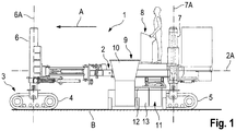
- FIGS. 1A and 1B show a slipform paver used in the European Patent Application EP 1 103 659 A2 is described in detail. Since the Slipform paver as such belongs to the state of the art, only the components of the construction machine essential to the invention are described here.
- the slipform paver 1 has a machine frame 2, which is supported by a chassis 3.
- the chassis 3 has two in the direction of travel or working A front crawler 4 and two rear crawler 5 on.
- the front and rear drives 4, 5 are respectively fixed to front and rear lifting columns 6, 7, which are mounted on the machine frame 2, so that the machine frame 2 in height relative to the bottom B is adjustable or machine frame and drives relative to each other are movable.
- the longitudinal axes 6A, 7A of the lifting columns 6, 7 run at a right angle to the longitudinal axis 2A of the machine frame 2.
- the concrete trough 9 has a chute 10 for the supply of concrete, which is arranged above a mold 11.
- the open at the bottom mold 11 is bounded at the top by a cover plate 12 and the sides of side plates 13.
- the concrete exits at the back of the mold 11, wherein the rear end of the mold 11 is located in the longitudinal direction of the slipform paver at the level of the longitudinal axes 7A of the rear lifting columns 7.
- the side plates 13 are height adjustable, so that concrete when lifting and lowering the machine frame 2 can not escape laterally.
- the height of the concrete trough 9 with respect to the floor B determines the height of the building to be erected, for example a baffle.
- an inventive slipform paver 1 as an example of a construction machine with reference to the FIGS. 2 to 6 described, in which the size of the individual parts of the sake of clarity but not drawn to scale.
- the slipform paver has two only foreshadowed front and rear drives 4, 5, to which two front and rear lifting columns 6, 7 are fixed, on which the front and rear drives 4, 5 are mounted, which stand up on the floor B.
- the concrete trough 9 is located next to the rear left Drive 5, wherein the rear end of the concrete trough 9 in the longitudinal direction of the machine frame 2 at the height of the longitudinal axis 7A of the rear lifting column 7 or the center of gravity of the footprint of the drive.
- the height of the cover plate 12 of the concrete trough 9 above the terrain surface and thus the height of the building to be constructed is determined by the position of the lifting columns 6, 7.
- the lifting columns 6, 7 are adjusted such that the cover plate 12 is at the correct height above the ground surface. This position of the lifting columns 6, 7 is hereinafter referred to as the starting position.
- the slipform paver has a central control or regulating unit 14, which is shown only schematically in the figures.
- the control or regulating unit 14 has a first control loop 14A, with which the stroke position of the rear lifting columns 7 is controlled such that the distance x of the cover plate 12 of the concrete trough to the ground remains constant and corresponds to a predetermined height of the building. With this regulation, the upper edge of the concrete trough follows the ground during the advancement of the construction machine.
- the distance x of the cover plate 12 of the concrete recess to the ground is measured with a distance sensor 15A, for example an ultrasonic sensor, which can lie in the longitudinal direction at the level of the axis 7A of the rear lifting column 7. The following describes a correction of this control.
- Fig. 8A shows in a highly simplified schematic representation and oversized size ratios, the movement of the concrete trough 9 in the case of a flat floor.
- This case is not critical.
- the upper edge 22A of the only suggestively illustrated structure 22, which corresponds to the upper edge of the concrete trough 9, is always at the same height when advancing the machine.
- Fig. 8B shows the movement of the concrete trough 9 in the case of a non-level bottom having a recess.
- the upper edge of the concrete recess follows the course of the terrain. Consequently, the upper edge 22A of the structure 22 is no longer at the same height in the longitudinal direction. However, the upper edge of the structure should be parallel to the surface of the floor B assumed to be the same.
- the control unit 14 has a second control circuit 14B.
- the second control loop 14B controls the front lifting columns 6 such that the machine frame 2 with the concrete trough 9 remains in parallel alignment with the surface B of the base B assumed to be the same.
- the front drives 6 overrun a terrain elevation
- the front elevation columns are retracted from the home position by the appropriate path so that the front drives are raised and the machine frame is held in parallel alignment with the ground surface.
- the front drives are extended from the starting position by the corresponding path. Structure and function of such a control unit are in the EP 2 104 768 B1 described in detail.
- the orientation of the machine frame 2 with respect to the terrain surface is detected with a device 15 only schematically shown in the figures, which can be designed differently.
- the machine frame orientation determining means 15 may include means for measuring the distance of the machine frame to the ground surface, which may include the rear distance sensor 15A and a front distance sensor 15B, for example, an ultrasonic sensor. From the difference of the distances measured with the distance sensors 15A and 15B to the ground, the orientation of the machine frame 2 can be determined. If the measured distance values are equal, it is assumed that the machine frame is in parallel alignment with the terrain surface. Such a determination of the orientation of the machine frame requires, however, that the distance to the as even assumed ground surface is measured, that is not the distance in the region of a depression is measured.
- An alternative embodiment of the device 15 provides means for measuring the inclination of the machine frame 2 with respect to the horizontal with a tilt sensor 15C.
- This device may receive the data from a GNSS-based device 15D or other system capable of providing data, in particular altitude information, from which the slope of the terrain can be calculated. If the inclination of the terrain is known, the difference between the inclination of the machine frame 2 measured with the inclination sensor 15C with respect to the horizontal and the inclination of the terrain surface, that is, the inclination of the ground. H. the inclination of the machine frame relative to the terrain surface, calculated.
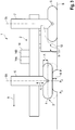
- FIGS. 2 to 4 show the lifting movement of the front drives 4 when driving over a bump.
- the control unit 14 controls the lifting columns 6 of the front drives 4 so that they are retracted accordingly when driving over the increase. If the footprint of the front drive reaches the point P 1 , the front lifting column 6 is driven so that the front drive 4 is retracted from the starting position. At the apex P 2 of the elevation, the lifting column 6 or the drive 4 is retracted from the starting position by the distance ⁇ which corresponds to the height H of the elevation. If the point P 3 happened, the lifting column 6 or the drive 4 is back in the starting position. Consequently, the machine frame 2 remains in parallel alignment with the ground surface.
- the control or regulation according to the invention provides for a correction of the regulation of the rear lifting columns 7 with the first control loop 14A in response to the control of the front lifting columns 6 with the second control loop 14B, the correction taking place with a predetermined time delay corresponding to the return of a predetermined time Distance L corresponds.
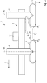
- FIGS. 4 to 6 show that the lifting movement of the rear lifting column 7 and the rear drive 5, the movement of the front lifting column 6 and the front Drive 4 is superimposed.
- the control unit 14 controls the lifting column 7 of the rear drive 5 in such a way that the rear drive 5 in addition to the predetermined by the first control stroke movement performs the same lifting movement as the front drive 4, which corresponds to the profile of the increase.
- the data describing the profile of the terrain increase receives the control unit 14 when driving over the increase with the front drive. 4
- the slipform paver has a first distance measuring device 16 for measuring the stroke position of the front lifting columns 6 and a second distance measuring device 17 for measuring the distance traveled by the construction machine.
- the first distance measuring device 16 measures the distance by which the front lifting columns 6 are retracted so that the machine frame remains in the correct position (FIG. FIGS. 2 to 4 ).
- the output signal of the first distance measuring device 16 is a quantity which correlates with the distance d between a reference point R on the machine frame 2 and the ground, wherein the reference point R can lie on the axis 6A of the front lifting column 6.
- the measurement data of the first distance measuring device 16 describe the profile of the increase, which is run over by the rear drives 5 with a time delay ( FIGS. 4 to 6 ).
- the time delay results from the feed rate of the slipform paver and the distance L between the front and rear drives 4, 5.
- the second distance measuring device 17 measures the path traveled by the front drives 4 after passing the elevation. When the measured traveled distance corresponds to the distance L between the front and rear drives 4, 5, controls the control unit 14, the lifting columns 7 of the rear drives 5 so that the lifting movement of the front lifting columns 6 and 4 drives the lifting movement of rear lifting columns 7 and 5 drives are superimposed. From the FIGS. 4 to 6 It can be seen that the concrete trough 9 is set when passing the increase with the rear drives 5 to the correct height with respect to the bottom B. When driving through a depression, the movements of the lifting columns or drives are reversed. Unevenness in the terrain does not lead to different heights of the structure ( FIGS. 8A to 8C ).
- a distance measuring device 18 may be provided which measures the distance d between a reference point R on the machine frame 2 and the bottom B.
- This distance measuring device 18 may include a distance sensor 18A, which is preferably arranged in front of the front drive 4. However, the distance sensor 18A can also be arranged on the longitudinal axis 6A of the front lifting column 6, so that the distance measurement can also be performed with the distance sensor 15B.
- Fig. 8C shows the additional stroke ⁇ of the rear lifting column 7 and the rear drive 5 when driving through a depression that has already been passed by the front drive 4.
- Fig. 8B shows that the correction of the control of the first control loop 14A as a function of the second control loop 14B results in the upper edge 22A of the structural body 22 remaining at the same level in the longitudinal direction even when passing through the recess.
- the rear lifting column 7 is extended by that amount ⁇ by which the front lifting column 6 has been previously extended.
- a road milling machine In a road milling machine, the same advantages arise as with a slipform paver. The only difference is that the construction machine has a milling drum 19 instead of a concrete trough.
- Fig. 7 shows a road milling machine 20 in a highly simplified schematic representation, but the size of the individual parts is not shown to scale. The corresponding parts are provided with the same reference numerals.
- the road milling machine 20 has a milling drum 19 which is arranged on the machine frame 2.
- the axis of the milling drum 19 is located in the longitudinal direction at the height of the axis of the rear lifting column 7 and the rear drive 5.
- the control or regulation of the lifting movement of the rear drives 5 with respect to the machine frame 2 results in that when driving over a partially occurring increase the milling depth remains constant with respect to the actual terrain surface.
Landscapes
- Engineering & Computer Science (AREA)
- Architecture (AREA)
- Civil Engineering (AREA)
- Structural Engineering (AREA)
- Mining & Mineral Resources (AREA)
- Mechanical Engineering (AREA)
- Chemical & Material Sciences (AREA)
- Combustion & Propulsion (AREA)
- Transportation (AREA)
- Road Paving Machines (AREA)
Claims (16)
- Engin automobile de construction, en particulier finisseur à coffrage glissant (1) ou fraiseuse de route (20), avec
un châssis (3) qui présente au moins un mécanisme de roulement avant (4) dressé sur le sol (B) dans le sens de travail (A) et au moins un mécanisme de roulement arrière (5) dressé sur le sol dans le sens de travail,
un bâti de machine (2), sur lequel est prévu un dispositif de travail (9, 19) qui présente un dispositif (9) pour le formage de matériau coulant ou un rouleau de fraisage (19),
dans lequel le bâti de machine (2) est porté par des dispositifs de levage (6, 7) associés aux mécanismes de roulement (4, 5) de sorte que le bâti de machine (2) et les mécanismes de roulement (4, 5) puissent être mobiles les uns par rapport aux autres et la hauteur et l'orientation du bâti de machine soient ainsi réglables par rapport au sol,
une unité de commande ou de réglage (14) pour la commande des dispositifs de levage associés aux mécanismes de roulement avant et arrière, dans lequel l'unité de commande ou de réglage (14) est configurée de telle manière que
l'unité de commande ou de réglage (14) prévoit un réglage du dispositif de levage arrière ou des dispositifs de levage arrière (7) de telle manière que le dispositif (9) pour le formage de matériau coulant ou le rouleau de fraisage (19) reste à une hauteur prédéfinie par rapport au sol pendant l'avance de l'engin de construction, et
l'unité de commande ou de réglage (14) prévoit un réglage du dispositif de levage avant ou des dispositifs de levage avant (6) de telle manière que le bâti de machine (2) reste dans une orientation prédéfinie par rapport au sol dans le sens longitudinal pendant l'avance de l'engin de construction,
caractérisé en ce que
l'unité de commande ou de réglage (14) est configurée de telle manière que pendant l'avance de l'engin de construction en fonction du réglage du dispositif de levage avant ou des dispositifs de levage avant (6) avec un retard temporel, un engagement dans le réglage du dispositif de levage arrière ou des dispositifs de levage arrière (7) soit entrepris de sorte que la hauteur du dispositif (9) pour le formage de matériau coulant ou du rouleau de fraisage (19) réglée par rapport au sol par le dispositif de levage arrière ou les dispositifs de levage arrière, soit corrigée au moins en partie pour la compensation des inégalités de sol. - Engin de construction selon la revendication 1, caractérisé en ce que l'unité de commande ou de réglage (14) est configurée de telle manière que pendant l'avance de l'engin de construction avec un retard temporel, un engagement dans le réglage du dispositif de levage arrière ou des dispositifs de levage arrière (7) soit entrepris en fonction d'une grandeur en corrélation avec la distance (d) entre un point de référence (R) sur le bâti de machine (2) et le sol (B).
- Engin de construction selon la revendication 2, caractérisé en ce que le point de référence (R) se trouve sur le bâti de machine (2) dans le sens de travail avant le mécanisme de roulement arrière ou les mécanismes de roulement arrière (5), en particulier avant le mécanisme de roulement avant ou les mécanismes de roulement avant (4).
- Engin de construction selon la revendication 2 ou 3, caractérisé en ce que l'unité de commande ou de réglage (14) est configurée de telle manière que pour une diminution de la distance (d) avec un retard temporel, le dispositif de levage arrière (7) soit rentré depuis la position prédéfinie par le réglage du dispositif de levage arrière, d'une course correspondante ou les dispositifs de levage arrière soient rentrés et pour une augmentation de la distance (d), le dispositif de levage arrière soit sorti d'une course correspondante ou les dispositifs de levage arrière soient sortis de sorte que le mouvement de levage du/des dispositif(s) de levage avant (6) soit superposé au mouvement de levage du/des dispositif(s) de levage arrière (7).
- Engin de construction selon l'une quelconque des revendications 2 à 4, caractérisé en ce que pour la détection d'une grandeur en corrélation avec la distance (d) entre un point de référence (R) sur le bâti de machine (2) et le sol (B), un dispositif de mesure de parcours (16) mesurant la position de levage du dispositif de levage avant ou des dispositifs de levage (6) avant est prévu.
- Engin de construction selon l'une quelconque des revendications 2 à 4, caractérisé en ce que pour la détection d'une grandeur en corrélation avec la distance (d) entre un point de référence (R) sur le bâti de machine (2) et le sol (B), un dispositif de mesure de distance (18) mesurant la distance (d) entre un point de référence (R) sur le bâti de machine (2) et le sol (B) est prévu.
- Engin de construction selon la revendication 6, caractérisé en ce que le dispositif de mesure de distance (18) présente un capteur de distance (18A).
- Engin de construction selon l'une quelconque des revendications 1 à 7, caractérisé en ce que l'unité de commande ou de réglage (14) présente un dispositif de mesure de parcours (17) pour la mesure de la distance parcourue par l'engin de construction, et en ce que l'unité de commande ou de réglage (14) est configurée de telle manière que la correction du réglage du dispositif de levage arrière ou des dispositifs de levage arrière (7) soit entreprise lorsque l'engin de construction a parcouru une distance prédéfinie, en particulier un parcours qui correspond sensiblement à la distance (L) entre les mécanismes de roulement avant et arrière (4, 5).
- Engin de construction selon l'une quelconque des revendications 1 à 8, caractérisé en ce que les dispositifs de levage avant et arrière sont des colonnes de levage hydrauliques (6, 7) qui relient le bâti de machine (2) et les mécanismes de roulement (4, 5), dans lequel les axes longitudinaux (6A, 7A) des colonnes de levage (6, 7) sont agencés à angle droit de l'axe longitudinal (2A) du bâti de machine (2), et en ce que l'unité de commande ou de réglage (14) est configurée de telle manière que le bâti de machine (2) reste dans le sens longitudinal dans une orientation parallèle par rapport au sol (B).
- Engin de construction selon l'une quelconque des revendications 1 à 9, caractérisé en ce que l'unité de commande ou de réglage (14) présente un dispositif (15) pour la détermination de l'orientation du bâti de machine (2) par rapport au sol (B), dans lequel le dispositif (15) pour la détermination de l'orientation du bâti de machine (2) présente par rapport au sol (B), de préférence un dispositif de mesure (15C) pour la mesure de l'inclinaison du bâti de machine (2) par rapport à l'horizontale et un dispositif (15D) pour la mise à disposition de données décrivant l'inclinaison du terrain, et le dispositif (15) pour la détermination de l'orientation du bâti de machine (2) est configuré de telle manière que la différence entre l'inclinaison du bâti de machine (2) par rapport à l'horizontale et l'inclinaison de la surface de terrain soit calculée.
- Engin de construction selon l'une quelconque des revendications 1 à 10, caractérisé en ce que l'engin de construction est un finisseur à coffrage glissant (1) avec un dispositif (9) pour le formage de matériau coulant, dans lequel la sortie du dispositif (9) pour le formage de matériau coulant est agencée dans le sens longitudinal du finisseur à coffrage glissant à la hauteur du mécanisme de roulement arrière ou des mécanismes de roulement arrière (5).
- Engin de construction selon l'une quelconque des revendications 1 à 10, caractérisé en ce que l'engin de construction est une fraiseuse de route (20) avec un rouleau de fraisage (19), dans lequel le rouleau de fraisage (19) est agencé dans le sens longitudinal de la fraiseuse de route à la hauteur du mécanisme de roulement arrière ou des mécanismes de roulement arrière (5).
- Procédé de commande d'un engin automobile de construction, en particulier d'un finisseur à coffrage glissant ou d'une fraiseuse de route, qui présente :un châssis qui a au moins un mécanisme de roulement avant dressé sur le sol dans le sens de travail et au moins un mécanisme de roulement arrière dressé sur le sol dans le sens de travail,un bâti de machine, sur lequel est prévu un dispositif de travail qui a un dispositif de formage de matériau coulant ou un rouleau de fraisage,des dispositifs de levage associés aux mécanismes de roulement qui portent le bâti de machine de sorte que le bâti de machine et les mécanismes de roulement soient mobiles les uns par rapport aux autres et la hauteur et l'orientation du bâti de machine soient réglables par rapport au sol,dans lequel pendant l'avance de l'engin de construction, le mouvement de levage du dispositif de levage arrière ou des dispositifs de levage arrière est réglé de telle manière que le dispositif pour le formage de matériau coulant ou le rouleau de fraisage reste à une hauteur prédéfinie par rapport au sol, etpendant l'avance de l'engin de construction, le mouvement de levage du dispositif de levage avant ou des dispositifs de levage avant est réglé de telle manière que le dispositif pour le formage de matériau coulant ou le rouleau de fraisage reste dans une orientation prédéfinie par rapport au sol,caractérisé en ce que
pendant l'avance de l'engin de construction en fonction du réglage du dispositif de levage avant ou des dispositifs de levage avant avec un retard temporel, un engagement dans le réglage du dispositif de levage arrière ou des dispositifs de levage arrière est entrepris, de sorte que la hauteur du dispositif pour le formage de matériau coulant ou du rouleau de fraisage par rapport au sol soit corrigée au moins en partie pour la compensation d'inégalités de sol. - Procédé selon la revendication 13, caractérisé en ce que pendant l'avance de l'engin de construction avec un retard temporel, un engagement dans le réglage du dispositif de levage arrière ou des dispositifs de levage arrière en fonction d'une grandeur en corrélation avec la distance (d) entre un point de référence (R) sur le bâti de machine et le sol est entrepris.
- Procédé selon la revendication 14, caractérisé en ce que le point de référence (R) se trouve sur le bâti de machine dans le sens de travail avant le mécanisme de roulement arrière ou les mécanismes de roulement arrière, en particulier avant le mécanisme de roulement avant ou les mécanismes de roulement avant, dans lequel pour une réduction de la distance (d) avec un retard temporel, le dispositif de levage arrière est rentré de la position prédéfinie par la réglage du dispositif de levage arrière, d'une course correspondante ou les dispositifs de levage arrière sont rentrés et pour une augmentation de la distance, le dispositif de levage arrière est sorti d'une course correspondante ou les dispositifs de levage arrière sont sortis de sorte que le mouvement de levage du/des dispositif(s) de levage avant soit superposé au mouvement de levage du/des dispositif(s) de levage arrière.
- Procédé selon la revendication 14 ou 15, caractérisé en ce que pour la détermination de la grandeur en corrélation avec la distance (d) entre un point de référence (R) sur le bâti de machine et le sol, la position de levage du dispositif de levage avant ou des dispositifs de levage avant est détectée.
Applications Claiming Priority (1)
| Application Number | Priority Date | Filing Date | Title |
|---|---|---|---|
| DE102014005077.7A DE102014005077A1 (de) | 2014-04-04 | 2014-04-04 | Selbstfahrende Baumaschine und Verfahren zum Steuern einer selbstfahrenden Baumaschine |
Publications (2)
| Publication Number | Publication Date |
|---|---|
| EP2927372A1 EP2927372A1 (fr) | 2015-10-07 |
| EP2927372B1 true EP2927372B1 (fr) | 2017-01-04 |
Family
ID=52780871
Family Applications (1)
| Application Number | Title | Priority Date | Filing Date |
|---|---|---|---|
| EP15160925.2A Active EP2927372B1 (fr) | 2014-04-04 | 2015-03-25 | Engin automobile et procédé de commande d'un engin automobile |
Country Status (4)
| Country | Link |
|---|---|
| US (2) | US9309632B2 (fr) |
| EP (1) | EP2927372B1 (fr) |
| CN (2) | CN104975554B (fr) |
| DE (1) | DE102014005077A1 (fr) |
Families Citing this family (17)
| Publication number | Priority date | Publication date | Assignee | Title |
|---|---|---|---|---|
| DE102013004757A1 (de) * | 2013-03-20 | 2014-09-25 | Dynapac Gmbh | Beschicker und Verfahren zum Umrüsten desselben |
| DE102014005077A1 (de) * | 2014-04-04 | 2015-10-08 | Wirtgen Gmbh | Selbstfahrende Baumaschine und Verfahren zum Steuern einer selbstfahrenden Baumaschine |
| ITUA20163959A1 (it) * | 2016-05-31 | 2017-12-01 | Massimo Bettella | Modulo semovente per trasporti eccezionali |
| CN106192622A (zh) * | 2016-08-31 | 2016-12-07 | 中铁四局集团第二工程有限公司 | 铁路混凝土路肩滑模摊铺机 |
| US11679639B2 (en) * | 2018-10-23 | 2023-06-20 | Caterpillar Paving Products Inc. | Systems and methods for controlling ground inclination of rotary cutting machines |
| US20200122542A1 (en) * | 2018-10-23 | 2020-04-23 | Caterpillar Paving Products Inc. | System for detecting machine elevation of a cold planer |
| US11421389B2 (en) * | 2018-12-28 | 2022-08-23 | Wirtgen Gmbh | Variable height mold |
| US11047095B2 (en) * | 2018-12-28 | 2021-06-29 | Wirtgen Gmbh | Variable height offset mold |
| CN109577155B (zh) * | 2019-01-10 | 2021-02-09 | 江苏工程职业技术学院 | 一种建筑机械用铣刨机 |
| US10844557B2 (en) * | 2019-03-27 | 2020-11-24 | Caterpillar Paving Products Inc. | Tool depth setting |
| US11549241B2 (en) * | 2019-12-23 | 2023-01-10 | Caterpillar Paving Products Inc. | Machine slope and pitch control based on dynamic center of gravity |
| PL3851584T3 (pl) * | 2020-01-16 | 2023-03-20 | Joseph Vögele AG | Wykańczarka ze sterowaniem zagęszczenia |
| CN112431101B (zh) * | 2020-11-27 | 2022-06-24 | 浙江绩丰机械有限公司 | 一种建筑机械用铣刨机 |
| CN112689423B (zh) * | 2021-01-14 | 2021-10-26 | 盐城工业职业技术学院 | 智能化的多功能机电控制设备 |
| DE102021118775A1 (de) * | 2021-04-06 | 2022-10-06 | Bomag Gmbh | Verfahren zum Einstellen der Hublage eines über Hubeinrichtungen mit Fahreinrichtungen verbundenen Maschinenrahmens einer Bodenfräsmaschine sowie Bodenfräsmaschine |
| CN115434224A (zh) * | 2022-09-13 | 2022-12-06 | 申晨璐 | 公路交通工程用标线清除方法 |
| US12553196B2 (en) * | 2022-12-14 | 2026-02-17 | Wirtgen Gmbh | Measuring paving thickness during slip form paving |
Family Cites Families (37)
| Publication number | Priority date | Publication date | Assignee | Title |
|---|---|---|---|---|
| US3423859A (en) | 1965-04-07 | 1969-01-28 | Machinery Inc Const | Road construction methods and apparatus |
| US3598027A (en) | 1969-02-05 | 1971-08-10 | Cmi Corp | Method of road construction |
| US3946506A (en) | 1972-02-14 | 1976-03-30 | Cmi Corporation | Trimmer type road construction apparatus with pivotally connected conveyor |
| US3969035A (en) * | 1974-02-28 | 1976-07-13 | Precision Paving Products Corporation | Slip from paving machine |
| US4139318A (en) | 1976-03-31 | 1979-02-13 | Cmi Corporation | Method and apparatus for planing a paved roadway |
| US4195740A (en) * | 1977-04-27 | 1980-04-01 | The Manitowoc Company, Inc. | Lift crane support system |
| US4222581A (en) * | 1978-04-07 | 1980-09-16 | Rigging International | Apparatus and method for moving a large object |
| US4325580A (en) | 1979-05-07 | 1982-04-20 | Cmi Corporation | Roadway planing apparatus |
| DE8810670U1 (de) | 1988-08-24 | 1989-01-26 | Moba-Electronic Gesellschaft für Mobil-Automation mbH, 6254 Elz | Höhensteuerungsvorrichtung |
| DE9114281U1 (de) | 1991-11-15 | 1992-01-09 | Moba-Electronic Gesellschaft für Mobil-Automation mbH, 6254 Elz | Ultraschall-Abstandsmeßeinrichtung für eine Baumaschine |
| US5315770A (en) | 1992-12-15 | 1994-05-31 | Astec Industries, Inc. | Roadway trenching apparatus |
| US5639181A (en) | 1993-06-15 | 1997-06-17 | Swisher, Jr.; George W. | Construction machine having compression-memory solid rubber tires |
| US5361550A (en) * | 1993-12-08 | 1994-11-08 | The United States Of America As Represented By The Secretary Of The Army | Movable hardened air form dome-shaped structure for containing hazardous, toxic, or radioactive airborne releases |
| US5378081A (en) | 1994-02-16 | 1995-01-03 | Swisher, Jr.; George W. | Milling machine with front-mounted cutter |
| DE19504495A1 (de) | 1995-02-12 | 1996-08-22 | Wirtgen Gmbh | Maschine zur Erneuerung von Fahrbahnen |
| US5607205A (en) | 1995-06-06 | 1997-03-04 | Caterpillar Inc. | Object responsive implement control system |
| DE19756676C1 (de) | 1997-12-19 | 1999-06-02 | Wirtgen Gmbh | Verfahren und Vorrichtung zum Abfräsen von Verkehrsflächen |
| US5984420A (en) | 1998-05-29 | 1999-11-16 | Wirtgen America, Inc. | Grade averaging system with floating boom and method of using the same |
| DE19957048C1 (de) | 1999-11-26 | 2001-08-09 | Wirtgen Gmbh | Gleitschalungsfertiger |
| IT1315336B1 (it) | 2000-05-11 | 2003-02-10 | Bitelli Spa | Metodo per la gestione integrata dei parametri relativi alla fresaturadi superfici stradali e macchina scarificatrice realizzante tale |
| EP1855899B1 (fr) | 2005-03-10 | 2013-09-18 | Wirtgen GmbH | Engin routier |
| DE102005044211A1 (de) | 2005-09-12 | 2007-03-22 | Wirtgen Gmbh | Selbstfahrende Baumaschine, sowie Hubsäule für eine Baumaschine |
| DE102006020293B4 (de) | 2006-04-27 | 2013-07-11 | Wirtgen Gmbh | Straßenbaumaschine, Nivelliereinrichtung sowie Verfahren zum Regeln der Frästiefe oder Fräsneigung bei einer Straßenbaumaschine |
| DE102006024123B4 (de) | 2006-05-22 | 2010-02-25 | Wirtgen Gmbh | Selbstfahrende Baumaschine, sowie Verfahren zum Bearbeiten von Bodenoberflächen |
| DE102006062129B4 (de) | 2006-12-22 | 2010-08-05 | Wirtgen Gmbh | Straßenbaumaschine sowie Verfahren zur Messung der Frästiefe |
| RU2401904C2 (ru) | 2006-12-22 | 2010-10-20 | Виртген Гмбх | Машина для измельчения дорожного покрытия и способ расположения контура машины параллельно поверхности земли |
| DE102008005066A1 (de) * | 2008-01-18 | 2009-07-30 | Wacker Construction Equipment Ag | Vibrationsplatte mit Riementrieb mit Mehrfachumlenkung |
| US7950478B2 (en) * | 2008-11-21 | 2011-05-31 | Intelliport Corporation | Heavy capacity transporter having multiple track-axles |
| DE102009040079A1 (de) | 2009-09-04 | 2011-03-10 | Wirtgen Gmbh | Gleitschalungsfertiger |
| CN201530976U (zh) * | 2009-11-03 | 2010-07-21 | 北京中成兴达建筑工程有限公司 | 自动抹平车 |
| CN101736678A (zh) * | 2009-11-24 | 2010-06-16 | 天宝导航有限公司 | 用可压缩材料层覆盖一区域的方法 |
| EP2514871B1 (fr) * | 2011-04-18 | 2016-05-11 | Joseph Vögele AG | Procédé pour la pose et le compactage d'une couche d'asphalte |
| US8794867B2 (en) * | 2011-05-26 | 2014-08-05 | Trimble Navigation Limited | Asphalt milling machine control and method |
| DE202012102062U1 (de) * | 2012-06-05 | 2013-09-12 | Nikolaus Berzen Ratzel | Crawler und System zum Transport von Lasten |
| DE102013010298A1 (de) * | 2013-06-19 | 2014-12-24 | Bomag Gmbh | Baumaschine, insbesondere Straßenfräse, und Verfahren zum Ausgleichen von Bodenunebenheiten für eine solche Baumaschine |
| DE102014005077A1 (de) * | 2014-04-04 | 2015-10-08 | Wirtgen Gmbh | Selbstfahrende Baumaschine und Verfahren zum Steuern einer selbstfahrenden Baumaschine |
| US9458581B1 (en) * | 2015-10-29 | 2016-10-04 | Gomaco Corporation | Coordinated and proportional grade and slope control using gain matrixes |
-
2014
- 2014-04-04 DE DE102014005077.7A patent/DE102014005077A1/de not_active Withdrawn
-
2015
- 2015-03-25 EP EP15160925.2A patent/EP2927372B1/fr active Active
- 2015-03-30 US US14/672,502 patent/US9309632B2/en active Active
- 2015-04-07 CN CN201510161108.3A patent/CN104975554B/zh active Active
- 2015-04-07 CN CN201520204665.4U patent/CN204919288U/zh not_active Withdrawn - After Issue
-
2016
- 2016-04-07 US US15/092,832 patent/US9702096B2/en active Active
Non-Patent Citations (1)
| Title |
|---|
| None * |
Also Published As
| Publication number | Publication date |
|---|---|
| EP2927372A1 (fr) | 2015-10-07 |
| US20170044727A1 (en) | 2017-02-16 |
| US9309632B2 (en) | 2016-04-12 |
| CN104975554B (zh) | 2017-11-21 |
| CN204919288U (zh) | 2015-12-30 |
| US9702096B2 (en) | 2017-07-11 |
| CN104975554A (zh) | 2015-10-14 |
| DE102014005077A1 (de) | 2015-10-08 |
| US20150284918A1 (en) | 2015-10-08 |
Similar Documents
| Publication | Publication Date | Title |
|---|---|---|
| EP2927372A1 (fr) | Engin automobile et procédé de commande d'un engin automobile | |
| EP3498914B1 (fr) | Ajustement de réglage de cylindre à niveler dans une finisseuse de route | |
| EP3228981B1 (fr) | Finisseuse de route dotée d'un dispositif de détection de l'épaisseur de couche et procédé de détection de l'épaisseur d'une couche de matériau installée | |
| DE69617129T2 (de) | Verfahren und vorrichtung für automatische laserausgerichtete nivellierung | |
| EP2025811B1 (fr) | Procédé pour l'application d'une couche de revêtement et finisseuse pour exécuter ce procédé | |
| DE102006062129B4 (de) | Straßenbaumaschine sowie Verfahren zur Messung der Frästiefe | |
| DE20009459U1 (de) | Straßenbauvorrichtung mit automatischem Steuerungssystem zur Schalungspositionierung | |
| EP2535457A1 (fr) | Finisseuse de route dotée d'un dispositif de mesure de l'épaisseur de couche | |
| EP2325393A1 (fr) | Procédé et finisseuse de route pour la fabrication d'un revêtement de route | |
| DE112016000713B4 (de) | Auto-Kalibrierung eines automatischen Nivelliersteuersystems in einer Arbeitsmaschine | |
| EP2735650A1 (fr) | Procédé de traitement de couches et son engin auxiliaire de construction | |
| EP3336254B1 (fr) | Engin de construction et procédé de conversion de l'engin de construction pour l'usinage d'un revêtement de sol | |
| EP0757735A1 (fr) | Vehicule pour la reparation des revetements de chaussees | |
| DE102022106808B3 (de) | Selbstfahrende Bodenfräsmaschine und Verfahren zum Steuern einer selbstfahrenden Bodenfräsmaschine | |
| EP0495171B1 (fr) | Procédé pour régler l'épaisseur d'une couche à poser avec un finisseur | |
| EP4515037A1 (fr) | Finisseuse d'asphalte coulé | |
| DE102025106501A1 (de) | Rüttlerfrequenzen für gleitschalungsfertiger | |
| DE102009023207A1 (de) | Straßenfertiger und Verfahren zum Verändern der Arbeitsbreite eines Straßenfertigers | |
| EP1375751A1 (fr) | Dispositif pour réaliser des surfaces planes avec matériau de construction en vrac | |
| DE102017202461A1 (de) | Stampfsysteme mit stufenlos einstellbarer amplitude und frequenz | |
| EP2857585A1 (fr) | Dispositif de lissage d'une surface plane d'une couche constituée de matériaux de construction durcissables | |
| EP3708711B1 (fr) | Système de capteurs avec unité de calcul pour finisseuse de route permettant de calculer une consommation de matière | |
| DE102018122598A1 (de) | Fahrbare Vorrichtung zur Ausbringung von Schüttgut | |
| EP3135814A1 (fr) | Dispositif de chargement pour finisseuse | |
| DE1784587A1 (de) | Fertiger zum Herstellen von platten- bzw.streifenfoermigen Betonbelaegen oder -bahnen |
Legal Events
| Date | Code | Title | Description |
|---|---|---|---|
| PUAI | Public reference made under article 153(3) epc to a published international application that has entered the european phase |
Free format text: ORIGINAL CODE: 0009012 |
|
| AK | Designated contracting states |
Kind code of ref document: A1 Designated state(s): AL AT BE BG CH CY CZ DE DK EE ES FI FR GB GR HR HU IE IS IT LI LT LU LV MC MK MT NL NO PL PT RO RS SE SI SK SM TR |
|
| AX | Request for extension of the european patent |
Extension state: BA ME |
|
| 17P | Request for examination filed |
Effective date: 20160311 |
|
| RBV | Designated contracting states (corrected) |
Designated state(s): AL AT BE BG CH CY CZ DE DK EE ES FI FR GB GR HR HU IE IS IT LI LT LU LV MC MK MT NL NO PL PT RO RS SE SI SK SM TR |
|
| RIC1 | Information provided on ipc code assigned before grant |
Ipc: E01C 23/07 20060101ALI20160701BHEP Ipc: E01C 23/088 20060101ALI20160701BHEP Ipc: E01C 19/48 20060101AFI20160701BHEP Ipc: B62D 55/116 20060101ALI20160701BHEP |
|
| GRAP | Despatch of communication of intention to grant a patent |
Free format text: ORIGINAL CODE: EPIDOSNIGR1 |
|
| INTG | Intention to grant announced |
Effective date: 20160812 |
|
| GRAS | Grant fee paid |
Free format text: ORIGINAL CODE: EPIDOSNIGR3 |
|
| STAA | Information on the status of an ep patent application or granted ep patent |
Free format text: STATUS: GRANT OF PATENT IS INTENDED |
|
| GRAA | (expected) grant |
Free format text: ORIGINAL CODE: 0009210 |
|
| STAA | Information on the status of an ep patent application or granted ep patent |
Free format text: STATUS: THE PATENT HAS BEEN GRANTED |
|
| AK | Designated contracting states |
Kind code of ref document: B1 Designated state(s): AL AT BE BG CH CY CZ DE DK EE ES FI FR GB GR HR HU IE IS IT LI LT LU LV MC MK MT NL NO PL PT RO RS SE SI SK SM TR |
|
| REG | Reference to a national code |
Ref country code: GB Ref legal event code: FG4D Free format text: NOT ENGLISH |
|
| REG | Reference to a national code |
Ref country code: CH Ref legal event code: EP |
|
| REG | Reference to a national code |
Ref country code: AT Ref legal event code: REF Ref document number: 859374 Country of ref document: AT Kind code of ref document: T Effective date: 20170115 |
|
| REG | Reference to a national code |
Ref country code: IE Ref legal event code: FG4D Free format text: LANGUAGE OF EP DOCUMENT: GERMAN |
|
| REG | Reference to a national code |
Ref country code: DE Ref legal event code: R096 Ref document number: 502015000459 Country of ref document: DE |
|
| REG | Reference to a national code |
Ref country code: FR Ref legal event code: PLFP Year of fee payment: 3 |
|
| REG | Reference to a national code |
Ref country code: SE Ref legal event code: TRGR |
|
| REG | Reference to a national code |
Ref country code: LT Ref legal event code: MG4D Ref country code: NL Ref legal event code: MP Effective date: 20170104 |
|
| PG25 | Lapsed in a contracting state [announced via postgrant information from national office to epo] |
Ref country code: NL Free format text: LAPSE BECAUSE OF FAILURE TO SUBMIT A TRANSLATION OF THE DESCRIPTION OR TO PAY THE FEE WITHIN THE PRESCRIBED TIME-LIMIT Effective date: 20170104 |
|
| PG25 | Lapsed in a contracting state [announced via postgrant information from national office to epo] |
Ref country code: FI Free format text: LAPSE BECAUSE OF FAILURE TO SUBMIT A TRANSLATION OF THE DESCRIPTION OR TO PAY THE FEE WITHIN THE PRESCRIBED TIME-LIMIT Effective date: 20170104 Ref country code: HR Free format text: LAPSE BECAUSE OF FAILURE TO SUBMIT A TRANSLATION OF THE DESCRIPTION OR TO PAY THE FEE WITHIN THE PRESCRIBED TIME-LIMIT Effective date: 20170104 Ref country code: NO Free format text: LAPSE BECAUSE OF FAILURE TO SUBMIT A TRANSLATION OF THE DESCRIPTION OR TO PAY THE FEE WITHIN THE PRESCRIBED TIME-LIMIT Effective date: 20170404 Ref country code: GR Free format text: LAPSE BECAUSE OF FAILURE TO SUBMIT A TRANSLATION OF THE DESCRIPTION OR TO PAY THE FEE WITHIN THE PRESCRIBED TIME-LIMIT Effective date: 20170405 Ref country code: IS Free format text: LAPSE BECAUSE OF FAILURE TO SUBMIT A TRANSLATION OF THE DESCRIPTION OR TO PAY THE FEE WITHIN THE PRESCRIBED TIME-LIMIT Effective date: 20170504 Ref country code: LT Free format text: LAPSE BECAUSE OF FAILURE TO SUBMIT A TRANSLATION OF THE DESCRIPTION OR TO PAY THE FEE WITHIN THE PRESCRIBED TIME-LIMIT Effective date: 20170104 |
|
| PG25 | Lapsed in a contracting state [announced via postgrant information from national office to epo] |
Ref country code: BG Free format text: LAPSE BECAUSE OF FAILURE TO SUBMIT A TRANSLATION OF THE DESCRIPTION OR TO PAY THE FEE WITHIN THE PRESCRIBED TIME-LIMIT Effective date: 20170404 Ref country code: PT Free format text: LAPSE BECAUSE OF FAILURE TO SUBMIT A TRANSLATION OF THE DESCRIPTION OR TO PAY THE FEE WITHIN THE PRESCRIBED TIME-LIMIT Effective date: 20170504 Ref country code: PL Free format text: LAPSE BECAUSE OF FAILURE TO SUBMIT A TRANSLATION OF THE DESCRIPTION OR TO PAY THE FEE WITHIN THE PRESCRIBED TIME-LIMIT Effective date: 20170104 Ref country code: ES Free format text: LAPSE BECAUSE OF FAILURE TO SUBMIT A TRANSLATION OF THE DESCRIPTION OR TO PAY THE FEE WITHIN THE PRESCRIBED TIME-LIMIT Effective date: 20170104 Ref country code: LV Free format text: LAPSE BECAUSE OF FAILURE TO SUBMIT A TRANSLATION OF THE DESCRIPTION OR TO PAY THE FEE WITHIN THE PRESCRIBED TIME-LIMIT Effective date: 20170104 Ref country code: RS Free format text: LAPSE BECAUSE OF FAILURE TO SUBMIT A TRANSLATION OF THE DESCRIPTION OR TO PAY THE FEE WITHIN THE PRESCRIBED TIME-LIMIT Effective date: 20170104 |
|
| REG | Reference to a national code |
Ref country code: DE Ref legal event code: R097 Ref document number: 502015000459 Country of ref document: DE |
|
| PG25 | Lapsed in a contracting state [announced via postgrant information from national office to epo] |
Ref country code: SK Free format text: LAPSE BECAUSE OF FAILURE TO SUBMIT A TRANSLATION OF THE DESCRIPTION OR TO PAY THE FEE WITHIN THE PRESCRIBED TIME-LIMIT Effective date: 20170104 Ref country code: CZ Free format text: LAPSE BECAUSE OF FAILURE TO SUBMIT A TRANSLATION OF THE DESCRIPTION OR TO PAY THE FEE WITHIN THE PRESCRIBED TIME-LIMIT Effective date: 20170104 Ref country code: EE Free format text: LAPSE BECAUSE OF FAILURE TO SUBMIT A TRANSLATION OF THE DESCRIPTION OR TO PAY THE FEE WITHIN THE PRESCRIBED TIME-LIMIT Effective date: 20170104 Ref country code: RO Free format text: LAPSE BECAUSE OF FAILURE TO SUBMIT A TRANSLATION OF THE DESCRIPTION OR TO PAY THE FEE WITHIN THE PRESCRIBED TIME-LIMIT Effective date: 20170104 |
|
| PLBE | No opposition filed within time limit |
Free format text: ORIGINAL CODE: 0009261 |
|
| STAA | Information on the status of an ep patent application or granted ep patent |
Free format text: STATUS: NO OPPOSITION FILED WITHIN TIME LIMIT |
|
| PG25 | Lapsed in a contracting state [announced via postgrant information from national office to epo] |
Ref country code: MC Free format text: LAPSE BECAUSE OF FAILURE TO SUBMIT A TRANSLATION OF THE DESCRIPTION OR TO PAY THE FEE WITHIN THE PRESCRIBED TIME-LIMIT Effective date: 20170104 Ref country code: DK Free format text: LAPSE BECAUSE OF FAILURE TO SUBMIT A TRANSLATION OF THE DESCRIPTION OR TO PAY THE FEE WITHIN THE PRESCRIBED TIME-LIMIT Effective date: 20170104 Ref country code: SM Free format text: LAPSE BECAUSE OF FAILURE TO SUBMIT A TRANSLATION OF THE DESCRIPTION OR TO PAY THE FEE WITHIN THE PRESCRIBED TIME-LIMIT Effective date: 20170104 |
|
| REG | Reference to a national code |
Ref country code: IE Ref legal event code: MM4A |
|
| PG25 | Lapsed in a contracting state [announced via postgrant information from national office to epo] |
Ref country code: LU Free format text: LAPSE BECAUSE OF NON-PAYMENT OF DUE FEES Effective date: 20170325 |
|
| PG25 | Lapsed in a contracting state [announced via postgrant information from national office to epo] |
Ref country code: IE Free format text: LAPSE BECAUSE OF NON-PAYMENT OF DUE FEES Effective date: 20170325 Ref country code: SI Free format text: LAPSE BECAUSE OF FAILURE TO SUBMIT A TRANSLATION OF THE DESCRIPTION OR TO PAY THE FEE WITHIN THE PRESCRIBED TIME-LIMIT Effective date: 20170104 |
|
| REG | Reference to a national code |
Ref country code: BE Ref legal event code: MM Effective date: 20170331 |
|
| REG | Reference to a national code |
Ref country code: FR Ref legal event code: PLFP Year of fee payment: 4 |
|
| PG25 | Lapsed in a contracting state [announced via postgrant information from national office to epo] |
Ref country code: BE Free format text: LAPSE BECAUSE OF NON-PAYMENT OF DUE FEES Effective date: 20170331 |
|
| PG25 | Lapsed in a contracting state [announced via postgrant information from national office to epo] |
Ref country code: MT Free format text: LAPSE BECAUSE OF FAILURE TO SUBMIT A TRANSLATION OF THE DESCRIPTION OR TO PAY THE FEE WITHIN THE PRESCRIBED TIME-LIMIT Effective date: 20170104 |
|
| REG | Reference to a national code |
Ref country code: CH Ref legal event code: PL |
|
| PG25 | Lapsed in a contracting state [announced via postgrant information from national office to epo] |
Ref country code: CH Free format text: LAPSE BECAUSE OF NON-PAYMENT OF DUE FEES Effective date: 20180331 Ref country code: LI Free format text: LAPSE BECAUSE OF NON-PAYMENT OF DUE FEES Effective date: 20180331 |
|
| PG25 | Lapsed in a contracting state [announced via postgrant information from national office to epo] |
Ref country code: HU Free format text: LAPSE BECAUSE OF FAILURE TO SUBMIT A TRANSLATION OF THE DESCRIPTION OR TO PAY THE FEE WITHIN THE PRESCRIBED TIME-LIMIT; INVALID AB INITIO Effective date: 20150325 |
|
| PG25 | Lapsed in a contracting state [announced via postgrant information from national office to epo] |
Ref country code: CY Free format text: LAPSE BECAUSE OF FAILURE TO SUBMIT A TRANSLATION OF THE DESCRIPTION OR TO PAY THE FEE WITHIN THE PRESCRIBED TIME-LIMIT Effective date: 20170104 |
|
| PG25 | Lapsed in a contracting state [announced via postgrant information from national office to epo] |
Ref country code: MK Free format text: LAPSE BECAUSE OF FAILURE TO SUBMIT A TRANSLATION OF THE DESCRIPTION OR TO PAY THE FEE WITHIN THE PRESCRIBED TIME-LIMIT Effective date: 20170104 |
|
| PG25 | Lapsed in a contracting state [announced via postgrant information from national office to epo] |
Ref country code: TR Free format text: LAPSE BECAUSE OF FAILURE TO SUBMIT A TRANSLATION OF THE DESCRIPTION OR TO PAY THE FEE WITHIN THE PRESCRIBED TIME-LIMIT Effective date: 20170104 |
|
| PG25 | Lapsed in a contracting state [announced via postgrant information from national office to epo] |
Ref country code: AL Free format text: LAPSE BECAUSE OF FAILURE TO SUBMIT A TRANSLATION OF THE DESCRIPTION OR TO PAY THE FEE WITHIN THE PRESCRIBED TIME-LIMIT Effective date: 20170104 |
|
| REG | Reference to a national code |
Ref country code: AT Ref legal event code: MM01 Ref document number: 859374 Country of ref document: AT Kind code of ref document: T Effective date: 20200325 |
|
| PG25 | Lapsed in a contracting state [announced via postgrant information from national office to epo] |
Ref country code: AT Free format text: LAPSE BECAUSE OF NON-PAYMENT OF DUE FEES Effective date: 20200325 |
|
| P01 | Opt-out of the competence of the unified patent court (upc) registered |
Effective date: 20230525 |
|
| PGFP | Annual fee paid to national office [announced via postgrant information from national office to epo] |
Ref country code: SE Payment date: 20260323 Year of fee payment: 12 |
|
| PGFP | Annual fee paid to national office [announced via postgrant information from national office to epo] |
Ref country code: GB Payment date: 20260324 Year of fee payment: 12 |
|
| PGFP | Annual fee paid to national office [announced via postgrant information from national office to epo] |
Ref country code: DE Payment date: 20260320 Year of fee payment: 12 |
|
| PGFP | Annual fee paid to national office [announced via postgrant information from national office to epo] |
Ref country code: FR Payment date: 20260325 Year of fee payment: 12 |
|
| PGFP | Annual fee paid to national office [announced via postgrant information from national office to epo] |
Ref country code: IT Payment date: 20260331 Year of fee payment: 12 |