EP2458700A1 - Elektrisches Gerät mit Stützvorrichtung für ein schwenkbares Gerät - Google Patents
Elektrisches Gerät mit Stützvorrichtung für ein schwenkbares Gerät Download PDFInfo
- Publication number
- EP2458700A1 EP2458700A1 EP11290488A EP11290488A EP2458700A1 EP 2458700 A1 EP2458700 A1 EP 2458700A1 EP 11290488 A EP11290488 A EP 11290488A EP 11290488 A EP11290488 A EP 11290488A EP 2458700 A1 EP2458700 A1 EP 2458700A1
- Authority
- EP
- European Patent Office
- Prior art keywords
- latch
- electrical equipment
- finishing plate
- support
- actuating button
- Prior art date
- Legal status (The legal status is an assumption and is not a legal conclusion. Google has not performed a legal analysis and makes no representation as to the accuracy of the status listed.)
- Granted
Links
Images


Classifications
-
- H—ELECTRICITY
- H02—GENERATION; CONVERSION OR DISTRIBUTION OF ELECTRIC POWER
- H02G—INSTALLATION OF ELECTRIC CABLES OR LINES, OR OF COMBINED OPTICAL AND ELECTRIC CABLES OR LINES
- H02G3/00—Installations of electric cables or lines or protective tubing therefor in or on buildings, equivalent structures or vehicles
- H02G3/02—Details
- H02G3/08—Distribution boxes; Connection or junction boxes
- H02G3/18—Distribution boxes; Connection or junction boxes providing line outlets
- H02G3/185—Floor outlets and access cups
Definitions
- the present invention relates, in general, the electrical equipment to be embedded in a wall, the mechanism is mounted on a rocking support to disappear under the wall or be accessible to projecting such a wall.
- the invention finds a particularly advantageous application in the production of a floor or office outlet or wall.
- an automatic ejection system is provided which continuously pushes the equipment support towards its raised position projecting from the finishing plate which bears against the mounting wall.
- the position of the latch is such that at the end of the tilting stroke of the equipment support, it rubs on a central portion of the hubcap attached to the equipment support. This repeated friction degrades the hubcap which affects the aesthetics of the equipment.
- the present invention proposes an electrical apparatus as defined in claim 1.
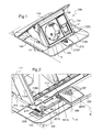
- an electrical apparatus 100 here a floor current plug to be embedded in a raised floor.
- the finishing plate 120 is advantageously made of metal material. It is intended to be applied against the front face of the recess wall of the electrical equipment, here the front face of the not shown technical floor.
- This finishing plate 120 is in the form of a relatively flat frame whose outer edge here follows a square outline. Of course, alternatively, it could be provided that the finishing plate has a rectangular or circular outer contour.
- the inner edge of the finishing plate 120 delimits a rectangular central opening ( figure 13 ) but it could also provide, according to other variants not shown, that this inner edge defines a square or circular opening. It could also be provided that the finishing plate for a multi-station apparatus comprises several openings, each intended to receive a tilting apparatus support.
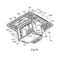
- the front face of the finishing plate 120 confers the aesthetics of the whole ( figures 1 and 8 ), while its rear face carries technical elements such as reinforcing ribs, abutment elements 123, chimneys 122, 126, orifices 124 and studs 125 for fixing various elements of the electrical equipment which will be explained in more detail later ( figures 13 and 14 ).
- the rear face comprises, along the outer edge of the finishing plate 120, a flat surface 120B for bearing against the embedding wall ( figure 13 ). This flat surface 120B of support of the finishing plate 120 could advantageously be set back to receive a seal with water and dust, this seal to marry any irregularities of the mounting wall.
- the apparatus support 110 is advantageously made of metallic material. It comprises two parallel main walls 111, 112 which extend perpendicular to the average plane P of the finishing plate 120 ( figures 1 and 14 ). These main walls 111, 112 are, at the rear of the support, connected to the two ends of a shaft of a tilting mechanism 400. At the front of the equipment support 110, the main walls 111, 112 are connected between them by a lower transverse beam 113. At the rear of the equipment support 110 but in front of the tilting mechanism 400, the main walls 111, 112 are also interconnected by an upper transverse beam (not referenced). The main walls 111, 112 and the lower transverse beams 113 and higher are derived from a single piece.
- a cover 130 is fixed to the two main walls 111, 112.
- the cover 130 is formed of a plate which extends perpendicularly to the main walls 111, 112. closes the space delimited between said main walls 111, 112 and overflows on either side of this space.
- the cover 130 is intended to close the central opening of the finishing plate 120 when the equipment support 110 is tilted to the lowered position ( figure 8 ).
- the cover 130 has a rectangular shape whose length is equal to the length of one side of the finishing plate 120 and whose width corresponds to the width of the central opening of the finishing plate 120.
- the finishing plate 120 comprises on the front face a recess 120C intended to receive the cover 130 when the equipment support 110 is tilted into position lowered ( figures 1 , 6 , 7 and 8 ).
- This recess 120C has the clearance close to the dimensions of the cover 130. It has in particular a depth equal to the thickness of the cover 130 (see figures 6 and 7 ), so that when the cover 130 is placed in the recess 120C of the finishing plate 120 its front face is flush with the front face of the finishing plate 120 to form a wall continuity ( figure 8 ). This is why the front face of the cover 130 has an aesthetic appearance that harmonizes with the aesthetic appearance of the front face of the trim plate 120.
- the cover 130 carries on its rear face an upper transverse beam 114, which extends, in the upper part, at the front of the support, transversely, from a main wall 111 to the other 112 of the equipment support 110 ( figures 1 and 14 ).
- the cover 130 and the upper transverse beam 114 are from the same single piece.
- the lower transverse beams 113 and 114 upper of the equipment support 110 are parallel.
- the main walls 111, 112 and the lower transverse beams 113 and 114 form a rectangular frame which delimits an insertion housing of various equipment mechanisms such as socket-outlets 1 or network connector 2 to be mounted on the equipment support 110 ( figure 1 ).
- the slices of the main walls 111, 112 and lower and upper beams 113, 114 form the front face 110A of the equipment support 110.
- This front face 110A is flat and surrounds the functional front faces of the mechanisms of equipment 1, 2 reported in the insertion housing and mounted on the equipment support 110.
- the tilting mechanism 400 is a conventional mechanism which is not a part of the present invention. It will not be described here in detail. It comprises a cylinder 401 traversed by a shaft at the ends 404 of which are fixed the main walls 111, 112 of the equipment support 110. Inside the cylinder is wound around the shaft a torsion spring under stress. The torsion spring connected to the shaft tends to rotate the shaft to tilting the equipment support 110 with cover 130 to its raised position.
- the cylinder 401 is secured to a plate 402 fixed by screws 403 to the rear face of the finishing plate 120. These screws 403 are screwed into threaded chimneys 126 provided on the rear face of the finishing plate 120.
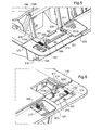
- the locking system 200 comprises a latch 210 mounted in translation in a direction D relative to the finishing plate 120 in a plane parallel to the average plane P of the latter, return means 230 which continuously push the latch 210 towards a locking position in which it projects into the opening of the trim plate 120 to lock said switchgear support 110 in either of its lowered and raised positions, and a button 220 actuation of the latch 210, which, in an actuated position, is adapted to be displaced in translation in the direction D, parallel to the average plane P of the finishing plate 120 to pull the latch 210 against said means 230 back from its locking position ( Figures 3 and 4 ).
- the actuating button 220 is adapted to be displaced in translation along an axis X perpendicular to the average plane P of the finishing plate 120, between a raised rest position ( figure 2 ) in which it is placed at a distance from the latch 210 and the actuating position lowered ( Figures 3 and 4 ) in which it cooperates with the latch 210.
- the latch 210 is an elongated wafer mounted in a housing delimited between the rear face of the trim plate 120, along a side 120A of the central opening of said trim plate 120, and a closure plate 300 secured by screws 302 on the rear face of the finishing plate 120 ( figures 13 and 14 ).
- the latch 210 is then adapted to move in translation along the direction D perpendicular to the corresponding side 120A of the finishing plate 120 which runs along its central opening.
- the closure plate 300 preferably metal, is pierced with through openings 301 for the passage of the fixing screws 302. It also comprises two through-openings 301 intended to engage two studs 125 for positioning the finishing plate 120 ( figure 14 ).
- the latch 210 extends in length over the entire width of the apparatus support 110, in front of said support, along the lower transverse beam 113 or greater 114.
- the latch 210 comprises, at least at one end, a locking tab 211 adapted to engage two notches 117, 118 provided in two corners of the front face of the equipment support 110, at the junction of a lower transverse beam 113 or 114 and a main wall 111, 112, for locking said equipment support 110 in its lowered positions ( figure 7 ) and noted ( figure 3 ).
- the latch 210 comprises at each end a locking tab 211 ( figure 13 ) and the equipment support 110 comprises in correspondence four notches 117, 118 provided at the four corners of its front face ( figure 14 ).
- the locking tabs 211 protrude from the rear edge 210A of the latch 210 facing the appliance support 110, while the opposite front edge 210B of the latch 210 facing the finishing plate 120 has a plurality of notches 212, 213 , 216 ( figure 13 ). Two of these substantially dovetail shaped notches 213 are located near and on either side of a central portion of the latch 210 which extends below the actuating button 220.
- the return means that continuously push the latch 210 towards its locking position comprise two compression springs 230 which intervene between parts 123, here abutments, of the finishing plate 120 and the ends of the latch 210. More particularly, each compression spring 230 bears against the bottom of a notch 216 of the latch 210, on the back of a locking tab 211 ( figure 13 ).
- the flat front face 110A of the equipment support 110 comprises a pan 117A, 118A beveled (here straight but it may be a curved surface in a variant not shown) which establishes the junction between said front face and the edge of each notch 117, 118.
- a return means 240 interposed between the latch 210 and the actuating button 220, which continuously pushes said actuating button 220 towards its raised rest position ( figure 10 ).
- This return means is a compression spring 240, part of which is housed in a first housing 223 provided in recess in the rear face 220B of the actuating button 220 and another part bears on the bottom of a second housing 215 provided in recessed in the front face of the central portion of the latch 210.
- This second housing 215 has an elongate shape in the translation direction D of the latch 210.
- the second housing 215 has an oblong shape.
- the form cooperation means comprise at least one stud 225 provided projecting on the rear face 220B of the actuating button 220 and at least one housing 213 of complementary shape to the stud, provided in the hollow in the face before latch 210.
- the actuating button 220 comprises at the two rear corners of its rear face 220B, two pads 225, 224 substantially to the dovetail contour, which project from two parallel lateral edges 221, 222 and the rear edge 226 of the button actuator 220.
- the latch 210 comprises the two notches 213, substantially dovetail-shaped, located near and on either side of the central portion of the latch 210.
- the actuating button 220 comprises on its front face 220A ribs 227 to grip the finger of a user and prevent it from slipping when actuating said button.
- the actuating button 220 is mounted in a through opening of the finishing plate 120 whose edge 121 is adapted to guide the translational movements of the actuating button 220.
- the actuating button 220 comprises two fins 221A, 222A projecting from two parallel edges 221, 222 and the finishing plate 120 has on its rear face, along two sides of the edge 121 of said opening which extend according to the translation direction D of the actuating button 220, two grooves 121A stepped in which are engaged said fins 221A, 222A (see Figures 2 to 4 ).
- the equipment support 110 is in the raised position.
- the actuating button 220 is in the raised rest position ( figure 10 ) remote from the latch 210, without cooperating with it.
- the latch 210 is pushed by the compression springs 230 in the locking position, its locking tabs 211 being engaged in the corresponding lower notches 118 of the equipment support 110.
- the user depresses the operation button 220 to push it into the opening of the trim plate 120 in the lowered operating position.
- the pads 225 of the actuating button 220 are engaged in the notches 213 of the latch 210 so that the actuating button 220 and the latch 210 are connected to each other, as shown in FIG. figure 3 .
- the latch 210 has not moved and it still locks the equipment support 110 in its raised position.
- the actuating button 220 then drives in its translational movement the latch 210, against the thrust of the compression springs 230, to set it back from its locking position.
- the locking tabs 211 is release the notches 118 of the equipment support 110.
- the fins 221A of the actuating button 220 navigate in the stepped grooves 121A of the finishing plate 120.
- the latch 210 is pushed in the opposite direction by the compression springs 230 towards its original locking position. It carries with it the actuating button 220 whose pads 225 cooperate with the notches 213 of the latch 210.
- the fins 221A navigate in opposite directions in the stepped grooves 121A of the 120.
- the fins 221A, the actuating button 220 arrive in the upper stages of said stepped grooves 121A and the compression spring 240 then pushes the actuating button 220 to place it in its position. raised rest in which it no longer cooperates with the latch 210 since its studs 225 are extracted from the notches 213 (see figure 5 ).
- the apparatus support 110 continues to be tilted to its lowered position.
- the front face 110A of said support does not come into contact with the ends of the locking tabs 211 of the latch 210 which returns to the locking position. It is only at the end of tilting stroke, just before reaching the lowered position, that the ends of the locking tabs 211 of the latch 210 slide on the flaps 117A in bevel of the front face 110A of the fitting support. 110 (see figure 6 ) before engaging in the upper notches 117 of the equipment support 110 to lock the latter in the lowered position (see figure 7 ).
- the cover 130 closes the central opening of the finishing plate 120 and obscures the equipment support 110 placed under it (see figure 8 ).
- the tilting mechanism 400 automatically causes said carrier to tilt to the raised position.
- the front face 110A of said support does not come into contact with the ends of the locking tabs 211 of the latch 210 which returns to the locking position from its unlock position. Only at the end of tilting stroke, just before reaching the raised position, the ends of the locking tabs 211 of the latch 210 slide on the sides 118A beveled of the front face 110A of the equipment support 110 (see figure 9 ) before engaging in the lower notches 118 of the equipment support 110 to lock the latter in the raised position (see figure 1 ).
Landscapes
- Engineering & Computer Science (AREA)
- Architecture (AREA)
- Civil Engineering (AREA)
- Structural Engineering (AREA)
- Casings For Electric Apparatus (AREA)
Applications Claiming Priority (1)
| Application Number | Priority Date | Filing Date | Title |
|---|---|---|---|
| FR1004626A FR2968141B1 (fr) | 2010-11-29 | 2010-11-29 | Appareillage electrique a support d'appareillage basculant |
Publications (2)
| Publication Number | Publication Date |
|---|---|
| EP2458700A1 true EP2458700A1 (de) | 2012-05-30 |
| EP2458700B1 EP2458700B1 (de) | 2015-02-18 |
Family
ID=44263022
Family Applications (1)
| Application Number | Title | Priority Date | Filing Date |
|---|---|---|---|
| EP11290488.3A Active EP2458700B1 (de) | 2010-11-29 | 2011-10-21 | Elektrisches Gerät mit Stützvorrichtung für ein schwenkbares Gerät |
Country Status (3)
| Country | Link |
|---|---|
| EP (1) | EP2458700B1 (de) |
| CN (1) | CN102544871B (de) |
| FR (1) | FR2968141B1 (de) |
Cited By (4)
| Publication number | Priority date | Publication date | Assignee | Title |
|---|---|---|---|---|
| CN106785639A (zh) * | 2017-01-06 | 2017-05-31 | 飞利富科技股份有限公司 | 一种用于面板插座的启闭结构 |
| CN107968302A (zh) * | 2017-12-29 | 2018-04-27 | 浙江捷诺电器有限公司 | 插座 |
| CN108926117A (zh) * | 2017-05-23 | 2018-12-04 | 西蒙独资有限公司 | 用于打开和关闭壳体的盖子的机械装置 |
| FR3103643A1 (fr) * | 2019-11-26 | 2021-05-28 | Legrand France | Appareillage avec un support d’appareillage basculant et un système de verrouillage débrayable au moyen d’une touche d’actionnement basculante |
Families Citing this family (1)
| Publication number | Priority date | Publication date | Assignee | Title |
|---|---|---|---|---|
| FR3103642B1 (fr) * | 2019-11-26 | 2021-10-29 | Legrand France | Appareillage à support d’appareillage basculant |
Citations (7)
| Publication number | Priority date | Publication date | Assignee | Title |
|---|---|---|---|---|
| JPH04244718A (ja) * | 1991-01-30 | 1992-09-01 | Matsushita Electric Works Ltd | アクセスフロア用接続器の構造 |
| JPH0698444A (ja) * | 1991-11-18 | 1994-04-08 | Setsuyou Kogyo Kk | フロアコンセント |
| CN2741224Y (zh) | 2004-10-24 | 2005-11-16 | 叶志荣 | 一种装一位三插的弹起式地面插座 |
| CN2845219Y (zh) | 2005-10-15 | 2006-12-06 | 叶志荣 | 超薄型弹起式地面插座 |
| CN2867645Y (zh) | 2006-01-09 | 2007-02-07 | 叶志荣 | 一种超薄型弹起式地面插座 |
| KR20090071028A (ko) | 2007-12-27 | 2009-07-01 | 주식회사 퍼맥스 | 책상 매립형 멀티콘센트 |
| KR20090083053A (ko) | 2008-01-29 | 2009-08-03 | 주식회사 퍼맥스 | 책상 매립형 멀티콘센트 |
-
2010
- 2010-11-29 FR FR1004626A patent/FR2968141B1/fr not_active Expired - Fee Related
-
2011
- 2011-10-21 EP EP11290488.3A patent/EP2458700B1/de active Active
- 2011-11-28 CN CN201110461871.XA patent/CN102544871B/zh active Active
Patent Citations (7)
| Publication number | Priority date | Publication date | Assignee | Title |
|---|---|---|---|---|
| JPH04244718A (ja) * | 1991-01-30 | 1992-09-01 | Matsushita Electric Works Ltd | アクセスフロア用接続器の構造 |
| JPH0698444A (ja) * | 1991-11-18 | 1994-04-08 | Setsuyou Kogyo Kk | フロアコンセント |
| CN2741224Y (zh) | 2004-10-24 | 2005-11-16 | 叶志荣 | 一种装一位三插的弹起式地面插座 |
| CN2845219Y (zh) | 2005-10-15 | 2006-12-06 | 叶志荣 | 超薄型弹起式地面插座 |
| CN2867645Y (zh) | 2006-01-09 | 2007-02-07 | 叶志荣 | 一种超薄型弹起式地面插座 |
| KR20090071028A (ko) | 2007-12-27 | 2009-07-01 | 주식회사 퍼맥스 | 책상 매립형 멀티콘센트 |
| KR20090083053A (ko) | 2008-01-29 | 2009-08-03 | 주식회사 퍼맥스 | 책상 매립형 멀티콘센트 |
Cited By (8)
| Publication number | Priority date | Publication date | Assignee | Title |
|---|---|---|---|---|
| CN106785639A (zh) * | 2017-01-06 | 2017-05-31 | 飞利富科技股份有限公司 | 一种用于面板插座的启闭结构 |
| CN106785639B (zh) * | 2017-01-06 | 2023-12-15 | 飞利富科技股份有限公司 | 一种用于面板插座的启闭结构 |
| CN108926117A (zh) * | 2017-05-23 | 2018-12-04 | 西蒙独资有限公司 | 用于打开和关闭壳体的盖子的机械装置 |
| CN107968302A (zh) * | 2017-12-29 | 2018-04-27 | 浙江捷诺电器有限公司 | 插座 |
| CN107968302B (zh) * | 2017-12-29 | 2023-10-20 | 浙江捷诺电器有限公司 | 插座 |
| FR3103643A1 (fr) * | 2019-11-26 | 2021-05-28 | Legrand France | Appareillage avec un support d’appareillage basculant et un système de verrouillage débrayable au moyen d’une touche d’actionnement basculante |
| EP3829014A1 (de) * | 2019-11-26 | 2021-06-02 | Legrand France | Gerät mit einer kippbaren gerätehalterung und einem verriegelungssystem, das mittels eines kippbaren betätigungsknopfes entriegelt werden kann |
| US12006756B2 (en) | 2019-11-26 | 2024-06-11 | Legrand France | Accessory with a tiltable accessory support and a locking system releasable by means of a tiltable actuator button |
Also Published As
| Publication number | Publication date |
|---|---|
| CN102544871A (zh) | 2012-07-04 |
| FR2968141B1 (fr) | 2012-12-28 |
| CN102544871B (zh) | 2014-09-24 |
| EP2458700B1 (de) | 2015-02-18 |
| FR2968141A1 (fr) | 2012-06-01 |
Similar Documents
| Publication | Publication Date | Title |
|---|---|---|
| EP1237453B1 (de) | Griffelement für kochgeschirr | |
| EP2458700B1 (de) | Elektrisches Gerät mit Stützvorrichtung für ein schwenkbares Gerät | |
| FR2728148A1 (fr) | Mecanisme de verrouillage d'extraction pour tiroirs superposes | |
| FR2716594A1 (fr) | Support pour radiotéléphone portatif . | |
| FR2873859A1 (fr) | Appareil electrique comportant une borne a connexion automatique | |
| EP0809457A1 (de) | Elektrisch betriebener handschläger und -rührer | |
| EP2458607B1 (de) | Verriegelungsvorrichtung zur Sicherung des Zugangs zur Kabeldose einer Stromzelle, und Stromzelle, die eine solche Vorrichtung enthält | |
| FR2912543A1 (fr) | Commutateur a verrouillage | |
| FR2852996A1 (fr) | Dispositif de verrouillage a deux poussees de commande | |
| EP2456021A1 (de) | Stromsteckdose mit seitlichen verschiebbaren Balken | |
| EP1328051A1 (de) | Vorrichtung zur Schienenbefestigung eines elektrischen Installationsgerätes | |
| EP1069632A1 (de) | Befestigungsanordnung einer Akkumulatorbatterie | |
| FR3078545A1 (fr) | Dispositif de rangement pour vehicule a ouvrant integrant un mecanisme d’actionnement a bouton poussoir. | |
| EP2146363A1 (de) | Modulares Elektrogerät, das mit einer Etikettenschutzhaube und einer Etikettenzughalterung ausgestattet ist | |
| EP2369699A1 (de) | Elektrischer Verteiler- oder Schaltkasten, der eine entfernbare Schienenauflagerung für die Montage von elektrischen Geräten umfasst | |
| EP2715894B1 (de) | Zugangsklappe für elektrogeräte | |
| EP2320012B1 (de) | Verschluss für die Klappe eines Kastens | |
| EP2320532B1 (de) | Vorrichtung zur Montage eines Pfostens am hinteren Teil eines Stromverteilungskastens, und mit einer solchen Vorrichtung ausgestatteter Stromverteilungskasten | |
| EP2341589B1 (de) | Vorrichtung zur Montage eines Gehäuseständers am hinteren Teil eines Stromverteilungskastens, und mit einer solchen Vorrichtung ausgestatteter Stromverteilungskasten | |
| EP0930813A1 (de) | Gehäuse, insbesondere für autonome Notbeleuchtungseinheit | |
| FR2791175A1 (fr) | Coupe-circuit a porte-fusible monte mobile | |
| EP4043290A1 (de) | Haltevorrichtung für ein tragbares elektronisches gerät in einem kraftfahrzeug | |
| EP2422416B1 (de) | Höheneinstellbare bodendose | |
| FR2722360A1 (fr) | Appareil electrique a rapporter par encliquetage sur un rail de support | |
| FR2953893A1 (fr) | Bloc mobile a rapporter sur un bloc fixe avec deux griffes de verrouillage debrayable et ensemble comportant un tel bloc mobile |
Legal Events
| Date | Code | Title | Description |
|---|---|---|---|
| PUAI | Public reference made under article 153(3) epc to a published international application that has entered the european phase |
Free format text: ORIGINAL CODE: 0009012 |
|
| AK | Designated contracting states |
Kind code of ref document: A1 Designated state(s): AL AT BE BG CH CY CZ DE DK EE ES FI FR GB GR HR HU IE IS IT LI LT LU LV MC MK MT NL NO PL PT RO RS SE SI SK SM TR |
|
| AX | Request for extension of the european patent |
Extension state: BA ME |
|
| 17P | Request for examination filed |
Effective date: 20120924 |
|
| GRAP | Despatch of communication of intention to grant a patent |
Free format text: ORIGINAL CODE: EPIDOSNIGR1 |
|
| INTG | Intention to grant announced |
Effective date: 20140910 |
|
| GRAS | Grant fee paid |
Free format text: ORIGINAL CODE: EPIDOSNIGR3 |
|
| GRAA | (expected) grant |
Free format text: ORIGINAL CODE: 0009210 |
|
| AK | Designated contracting states |
Kind code of ref document: B1 Designated state(s): AL AT BE BG CH CY CZ DE DK EE ES FI FR GB GR HR HU IE IS IT LI LT LU LV MC MK MT NL NO PL PT RO RS SE SI SK SM TR |
|
| REG | Reference to a national code |
Ref country code: GB Ref legal event code: FG4D Free format text: NOT ENGLISH |
|
| REG | Reference to a national code |
Ref country code: CH Ref legal event code: EP |
|
| REG | Reference to a national code |
Ref country code: AT Ref legal event code: REF Ref document number: 710995 Country of ref document: AT Kind code of ref document: T Effective date: 20150315 |
|
| REG | Reference to a national code |
Ref country code: IE Ref legal event code: FG4D Free format text: LANGUAGE OF EP DOCUMENT: FRENCH |
|
| REG | Reference to a national code |
Ref country code: DE Ref legal event code: R096 Ref document number: 602011013755 Country of ref document: DE Effective date: 20150402 |
|
| REG | Reference to a national code |
Ref country code: NL Ref legal event code: VDEP Effective date: 20150218 |
|
| REG | Reference to a national code |
Ref country code: AT Ref legal event code: MK05 Ref document number: 710995 Country of ref document: AT Kind code of ref document: T Effective date: 20150218 |
|
| REG | Reference to a national code |
Ref country code: LT Ref legal event code: MG4D |
|
| PG25 | Lapsed in a contracting state [announced via postgrant information from national office to epo] |
Ref country code: HR Free format text: LAPSE BECAUSE OF FAILURE TO SUBMIT A TRANSLATION OF THE DESCRIPTION OR TO PAY THE FEE WITHIN THE PRESCRIBED TIME-LIMIT Effective date: 20150218 Ref country code: ES Free format text: LAPSE BECAUSE OF FAILURE TO SUBMIT A TRANSLATION OF THE DESCRIPTION OR TO PAY THE FEE WITHIN THE PRESCRIBED TIME-LIMIT Effective date: 20150218 Ref country code: NO Free format text: LAPSE BECAUSE OF FAILURE TO SUBMIT A TRANSLATION OF THE DESCRIPTION OR TO PAY THE FEE WITHIN THE PRESCRIBED TIME-LIMIT Effective date: 20150518 Ref country code: LT Free format text: LAPSE BECAUSE OF FAILURE TO SUBMIT A TRANSLATION OF THE DESCRIPTION OR TO PAY THE FEE WITHIN THE PRESCRIBED TIME-LIMIT Effective date: 20150218 Ref country code: SE Free format text: LAPSE BECAUSE OF FAILURE TO SUBMIT A TRANSLATION OF THE DESCRIPTION OR TO PAY THE FEE WITHIN THE PRESCRIBED TIME-LIMIT Effective date: 20150218 Ref country code: FI Free format text: LAPSE BECAUSE OF FAILURE TO SUBMIT A TRANSLATION OF THE DESCRIPTION OR TO PAY THE FEE WITHIN THE PRESCRIBED TIME-LIMIT Effective date: 20150218 |
|
| PG25 | Lapsed in a contracting state [announced via postgrant information from national office to epo] |
Ref country code: AT Free format text: LAPSE BECAUSE OF FAILURE TO SUBMIT A TRANSLATION OF THE DESCRIPTION OR TO PAY THE FEE WITHIN THE PRESCRIBED TIME-LIMIT Effective date: 20150218 Ref country code: RS Free format text: LAPSE BECAUSE OF FAILURE TO SUBMIT A TRANSLATION OF THE DESCRIPTION OR TO PAY THE FEE WITHIN THE PRESCRIBED TIME-LIMIT Effective date: 20150218 Ref country code: LV Free format text: LAPSE BECAUSE OF FAILURE TO SUBMIT A TRANSLATION OF THE DESCRIPTION OR TO PAY THE FEE WITHIN THE PRESCRIBED TIME-LIMIT Effective date: 20150218 Ref country code: NL Free format text: LAPSE BECAUSE OF FAILURE TO SUBMIT A TRANSLATION OF THE DESCRIPTION OR TO PAY THE FEE WITHIN THE PRESCRIBED TIME-LIMIT Effective date: 20150218 Ref country code: IS Free format text: LAPSE BECAUSE OF FAILURE TO SUBMIT A TRANSLATION OF THE DESCRIPTION OR TO PAY THE FEE WITHIN THE PRESCRIBED TIME-LIMIT Effective date: 20150618 |
|
| REG | Reference to a national code |
Ref country code: FR Ref legal event code: PLFP Year of fee payment: 5 |
|
| PG25 | Lapsed in a contracting state [announced via postgrant information from national office to epo] |
Ref country code: SK Free format text: LAPSE BECAUSE OF FAILURE TO SUBMIT A TRANSLATION OF THE DESCRIPTION OR TO PAY THE FEE WITHIN THE PRESCRIBED TIME-LIMIT Effective date: 20150218 Ref country code: EE Free format text: LAPSE BECAUSE OF FAILURE TO SUBMIT A TRANSLATION OF THE DESCRIPTION OR TO PAY THE FEE WITHIN THE PRESCRIBED TIME-LIMIT Effective date: 20150218 Ref country code: RO Free format text: LAPSE BECAUSE OF FAILURE TO SUBMIT A TRANSLATION OF THE DESCRIPTION OR TO PAY THE FEE WITHIN THE PRESCRIBED TIME-LIMIT Effective date: 20150218 Ref country code: CZ Free format text: LAPSE BECAUSE OF FAILURE TO SUBMIT A TRANSLATION OF THE DESCRIPTION OR TO PAY THE FEE WITHIN THE PRESCRIBED TIME-LIMIT Effective date: 20150218 Ref country code: DK Free format text: LAPSE BECAUSE OF FAILURE TO SUBMIT A TRANSLATION OF THE DESCRIPTION OR TO PAY THE FEE WITHIN THE PRESCRIBED TIME-LIMIT Effective date: 20150218 |
|
| REG | Reference to a national code |
Ref country code: DE Ref legal event code: R097 Ref document number: 602011013755 Country of ref document: DE |
|
| PG25 | Lapsed in a contracting state [announced via postgrant information from national office to epo] |
Ref country code: PL Free format text: LAPSE BECAUSE OF FAILURE TO SUBMIT A TRANSLATION OF THE DESCRIPTION OR TO PAY THE FEE WITHIN THE PRESCRIBED TIME-LIMIT Effective date: 20150218 |
|
| PLBE | No opposition filed within time limit |
Free format text: ORIGINAL CODE: 0009261 |
|
| STAA | Information on the status of an ep patent application or granted ep patent |
Free format text: STATUS: NO OPPOSITION FILED WITHIN TIME LIMIT |
|
| PG25 | Lapsed in a contracting state [announced via postgrant information from national office to epo] |
Ref country code: IT Free format text: LAPSE BECAUSE OF FAILURE TO SUBMIT A TRANSLATION OF THE DESCRIPTION OR TO PAY THE FEE WITHIN THE PRESCRIBED TIME-LIMIT Effective date: 20150218 |
|
| 26N | No opposition filed |
Effective date: 20151119 |
|
| PG25 | Lapsed in a contracting state [announced via postgrant information from national office to epo] |
Ref country code: SI Free format text: LAPSE BECAUSE OF FAILURE TO SUBMIT A TRANSLATION OF THE DESCRIPTION OR TO PAY THE FEE WITHIN THE PRESCRIBED TIME-LIMIT Effective date: 20150218 |
|
| PG25 | Lapsed in a contracting state [announced via postgrant information from national office to epo] |
Ref country code: LU Free format text: LAPSE BECAUSE OF FAILURE TO SUBMIT A TRANSLATION OF THE DESCRIPTION OR TO PAY THE FEE WITHIN THE PRESCRIBED TIME-LIMIT Effective date: 20151021 |
|
| REG | Reference to a national code |
Ref country code: CH Ref legal event code: PL |
|
| GBPC | Gb: european patent ceased through non-payment of renewal fee |
Effective date: 20151021 |
|
| PG25 | Lapsed in a contracting state [announced via postgrant information from national office to epo] |
Ref country code: MC Free format text: LAPSE BECAUSE OF FAILURE TO SUBMIT A TRANSLATION OF THE DESCRIPTION OR TO PAY THE FEE WITHIN THE PRESCRIBED TIME-LIMIT Effective date: 20150218 |
|
| REG | Reference to a national code |
Ref country code: IE Ref legal event code: MM4A |
|
| PG25 | Lapsed in a contracting state [announced via postgrant information from national office to epo] |
Ref country code: GB Free format text: LAPSE BECAUSE OF NON-PAYMENT OF DUE FEES Effective date: 20151021 Ref country code: LI Free format text: LAPSE BECAUSE OF NON-PAYMENT OF DUE FEES Effective date: 20151031 Ref country code: CH Free format text: LAPSE BECAUSE OF NON-PAYMENT OF DUE FEES Effective date: 20151031 |
|
| REG | Reference to a national code |
Ref country code: FR Ref legal event code: PLFP Year of fee payment: 6 |
|
| PG25 | Lapsed in a contracting state [announced via postgrant information from national office to epo] |
Ref country code: IE Free format text: LAPSE BECAUSE OF NON-PAYMENT OF DUE FEES Effective date: 20151021 |
|
| PG25 | Lapsed in a contracting state [announced via postgrant information from national office to epo] |
Ref country code: BG Free format text: LAPSE BECAUSE OF FAILURE TO SUBMIT A TRANSLATION OF THE DESCRIPTION OR TO PAY THE FEE WITHIN THE PRESCRIBED TIME-LIMIT Effective date: 20150218 Ref country code: SM Free format text: LAPSE BECAUSE OF FAILURE TO SUBMIT A TRANSLATION OF THE DESCRIPTION OR TO PAY THE FEE WITHIN THE PRESCRIBED TIME-LIMIT Effective date: 20150218 Ref country code: HU Free format text: LAPSE BECAUSE OF FAILURE TO SUBMIT A TRANSLATION OF THE DESCRIPTION OR TO PAY THE FEE WITHIN THE PRESCRIBED TIME-LIMIT; INVALID AB INITIO Effective date: 20111021 |
|
| PG25 | Lapsed in a contracting state [announced via postgrant information from national office to epo] |
Ref country code: CY Free format text: LAPSE BECAUSE OF FAILURE TO SUBMIT A TRANSLATION OF THE DESCRIPTION OR TO PAY THE FEE WITHIN THE PRESCRIBED TIME-LIMIT Effective date: 20150218 Ref country code: GR Free format text: LAPSE BECAUSE OF FAILURE TO SUBMIT A TRANSLATION OF THE DESCRIPTION OR TO PAY THE FEE WITHIN THE PRESCRIBED TIME-LIMIT Effective date: 20150218 |
|
| PG25 | Lapsed in a contracting state [announced via postgrant information from national office to epo] |
Ref country code: BE Free format text: LAPSE BECAUSE OF NON-PAYMENT OF DUE FEES Effective date: 20151031 |
|
| PG25 | Lapsed in a contracting state [announced via postgrant information from national office to epo] |
Ref country code: MT Free format text: LAPSE BECAUSE OF FAILURE TO SUBMIT A TRANSLATION OF THE DESCRIPTION OR TO PAY THE FEE WITHIN THE PRESCRIBED TIME-LIMIT Effective date: 20150218 Ref country code: TR Free format text: LAPSE BECAUSE OF FAILURE TO SUBMIT A TRANSLATION OF THE DESCRIPTION OR TO PAY THE FEE WITHIN THE PRESCRIBED TIME-LIMIT Effective date: 20150218 |
|
| REG | Reference to a national code |
Ref country code: FR Ref legal event code: PLFP Year of fee payment: 7 |
|
| PG25 | Lapsed in a contracting state [announced via postgrant information from national office to epo] |
Ref country code: PT Free format text: LAPSE BECAUSE OF FAILURE TO SUBMIT A TRANSLATION OF THE DESCRIPTION OR TO PAY THE FEE WITHIN THE PRESCRIBED TIME-LIMIT Effective date: 20150218 Ref country code: MK Free format text: LAPSE BECAUSE OF FAILURE TO SUBMIT A TRANSLATION OF THE DESCRIPTION OR TO PAY THE FEE WITHIN THE PRESCRIBED TIME-LIMIT Effective date: 20150218 |
|
| REG | Reference to a national code |
Ref country code: FR Ref legal event code: PLFP Year of fee payment: 8 |
|
| PG25 | Lapsed in a contracting state [announced via postgrant information from national office to epo] |
Ref country code: AL Free format text: LAPSE BECAUSE OF FAILURE TO SUBMIT A TRANSLATION OF THE DESCRIPTION OR TO PAY THE FEE WITHIN THE PRESCRIBED TIME-LIMIT Effective date: 20150218 |
|
| PGFP | Annual fee paid to national office [announced via postgrant information from national office to epo] |
Ref country code: FR Payment date: 20250924 Year of fee payment: 15 |
|
| PGFP | Annual fee paid to national office [announced via postgrant information from national office to epo] |
Ref country code: DE Payment date: 20250923 Year of fee payment: 15 |