EP2460421A1 - Dispositif de transport pour transporter des produits en forme de tige de l'industrie de traitement du tabac - Google Patents
Dispositif de transport pour transporter des produits en forme de tige de l'industrie de traitement du tabac Download PDFInfo
- Publication number
- EP2460421A1 EP2460421A1 EP11190692A EP11190692A EP2460421A1 EP 2460421 A1 EP2460421 A1 EP 2460421A1 EP 11190692 A EP11190692 A EP 11190692A EP 11190692 A EP11190692 A EP 11190692A EP 2460421 A1 EP2460421 A1 EP 2460421A1
- Authority
- EP
- European Patent Office
- Prior art keywords
- receptacles
- control
- lever arms
- products
- lever
- Prior art date
- Legal status (The legal status is an assumption and is not a legal conclusion. Google has not performed a legal analysis and makes no representation as to the accuracy of the status listed.)
- Withdrawn
Links
- 238000012545 processing Methods 0.000 title claims description 9
- 241000208125 Nicotiana Species 0.000 title description 7
- 235000002637 Nicotiana tabacum Nutrition 0.000 title description 7
- 238000012546 transfer Methods 0.000 claims description 43
- 230000008878 coupling Effects 0.000 claims description 8
- 238000010168 coupling process Methods 0.000 claims description 8
- 238000005859 coupling reaction Methods 0.000 claims description 8
- 230000032258 transport Effects 0.000 claims description 8
- 230000005540 biological transmission Effects 0.000 claims description 4
- 230000002093 peripheral effect Effects 0.000 claims description 2
- 239000000853 adhesive Substances 0.000 description 17
- 230000001070 adhesive effect Effects 0.000 description 17
- 230000008901 benefit Effects 0.000 description 6
- 230000008859 change Effects 0.000 description 6
- 238000000034 method Methods 0.000 description 5
- 230000008569 process Effects 0.000 description 5
- 238000013461 design Methods 0.000 description 3
- 230000002349 favourable effect Effects 0.000 description 3
- 239000003292 glue Substances 0.000 description 3
- 230000000737 periodic effect Effects 0.000 description 3
- 230000007246 mechanism Effects 0.000 description 2
- 230000000903 blocking effect Effects 0.000 description 1
- 235000019504 cigarettes Nutrition 0.000 description 1
- 238000011161 development Methods 0.000 description 1
- 238000006073 displacement reaction Methods 0.000 description 1
- 238000004519 manufacturing process Methods 0.000 description 1
- 210000005239 tubule Anatomy 0.000 description 1
Images


Classifications
-
- A—HUMAN NECESSITIES
- A24—TOBACCO; CIGARS; CIGARETTES; SIMULATED SMOKING DEVICES; SMOKERS' REQUISITES
- A24C—MACHINES FOR MAKING CIGARS OR CIGARETTES
- A24C5/00—Making cigarettes; Making tipping materials for, or attaching filters or mouthpieces to, cigars or cigarettes
- A24C5/32—Separating, ordering, counting or examining cigarettes; Regulating the feeding of tobacco according to rod or cigarette condition
- A24C5/322—Transporting cigarettes during manufacturing
- A24C5/326—Transporting cigarettes during manufacturing with lateral transferring means
-
- A—HUMAN NECESSITIES
- A24—TOBACCO; CIGARS; CIGARETTES; SIMULATED SMOKING DEVICES; SMOKERS' REQUISITES
- A24C—MACHINES FOR MAKING CIGARS OR CIGARETTES
- A24C5/00—Making cigarettes; Making tipping materials for, or attaching filters or mouthpieces to, cigars or cigarettes
- A24C5/32—Separating, ordering, counting or examining cigarettes; Regulating the feeding of tobacco according to rod or cigarette condition
- A24C5/322—Transporting cigarettes during manufacturing
- A24C5/327—Construction details of the cigarette transport drum
Definitions
- the invention relates to a conveying device for conveying rod-shaped products of the tobacco-processing industry with the features of the preamble of claim 1.
- a generic conveyor is for example from the DE 41 29 672 A1 known.
- the conveyor comprises a first revolving longitudinal conveyor with receptacles for receiving in each case two products conveyed longitudinally on parallel tracks in parallel and for delivering the products to receptacles of a peripheral transverse conveyor which transports the products across the axis. Since the receptacles of the longitudinal conveyor are arranged parallel to each other at a distance corresponding to the parallel paths of the longitudinally axially conveyed products, the receptacles of the transverse conveyor at the time of adoption of the products in the takeover point must also have a corresponding orientation.
- the images must be arranged at a second transfer point of the cross conveyor on an identical radius.
- at least one group of recordings of the cross conveyor is provided with a control device by which the recordings of the cross conveyor is moved back to take over the products in the direction of a recorded with a product recording of the longitudinal conveyor and after the takeover of the product in the direction of the cross conveyor.
- Those recordings which are arranged between the moving recordings are in each case arranged fixedly on the transverse conveyer.
- the moving recordings of the cross conveyor are arranged on pivot levers whose movement is controlled by being guided at one end in a control cam of a fixed control plate.
- the control disk with the control contour thus forms the intended control device.
- the products in the moving shots are basically carried away in a different sequence of movements of the longitudinal conveyor than the products conveyed away in the fixed shots.
- rod-shaped products of the tobacco-processing industry are understood as meaning cigarettes, cigarillos, filters and the like which have a tobacco rod or filter strand which is fixed in form by a wrapping web.
- the tobacco potion or filter strand is placed in a previous step on the wrapping web, which is wrapped around the tobacco rod or the filter strand by the shape of a format reason in the further transport.
- an edge of the wrapping web is provided with a glue trace and then placed with the glue trace on the opposite edge and glued.
- After bonding the edges of the endless fixed by the wrapping tobacco rod or filter strand is cut in a cutter into products of single or multiple use length. In this state, the products are picked up by the longitudinal conveyor, the orientation of the adhesive seams of the wrapping webs of the products being substantially identical or at least defined by the processing process.
- the products and the filters are assembled in a filter tying machine and joined together with an additional tipping paper.
- the tipping paper is provided with glue and glued by superimposing the edges.
- the seam of the tipping paper thus represents a second adhesive seam.
- the adhesive seams of the wrapping web of the tobacco rod and the lining paper should not be arranged one above the other.
- the recordings of the transverse conveyor have the above-described different sequence of movements, in particular a receptacle being movable and a receptacle being fixedly arranged on the transverse conveyor, the relative orientation of the seams of the wrappings of the products to one another is changed at least slightly, which may lead, under unfavorable circumstances, that the adhesive seam of the tipping paper then comes to rest at least in some of the products on the adhesive seam of the wrapping web.
- the object of the invention is to further develop a generic conveying device such that the seams of the wrapping webs of the products taken over by the longitudinal conveyor in the recordings of the transverse conveyor have as identical an orientation as possible, so that the uniform alignment of the adhesive seams during the subsequent processing process can ensure that the adhesive seam of the subsequently attached covering paper does not come to lie above the adhesive seam of the wrapping web.
- the invention it is proposed to solve the problem that at the periphery of the cross conveyor between the first moving recordings second receptacles are provided, which are respectively fixedly arranged on the transverse conveyor, and execute a controlled by the control device rotational movement, which at least partially one to the pivoting movement of the first record has rectified direction of rotation.
- the proposed solution provides the advantage that the second recordings perform a rotational movement from a transfer position to a transfer position, by which the existing existing by the sole pivotal movement of the first recording possible relative angular offset of the joints of the arranged in the receptacles products be reduced.
- the images can be aligned differently by the rotational movement in the takeover and transfer points, so that they can be dimensioned differently and in particular larger in the circumferential direction, without disturbing the movement. Due to the enlarged images, the transfer and acceptance of the products can be made more process-reliable overall with less overpressing.
- the term "rectified direction of rotation" is to be understood in the sense of the invention that the second recordings from the transfer position of the products during the further rotational movement of the transverse conveyor to perform a rotational movement to the pivotal movement of the first lever arms and held in the receptacles arranged thereon, so that the products in the second shots of the second lever arms from the takeover position be rotated in the transfer position of the products by a rectified angle.
- the second recordings are rotated in the same direction during the rotational movement of the transverse conveyor as the products in the receptacles of the first lever arms.
- the rotational movement of the recordings can also be designed differently in sections, it is only important that the images are rotated from the transfer position to the transfer of the products to a subsequent transfer drum in the same direction and ideally by an identical angle. It is not excluded that the recordings are sometimes partially rotated in opposite directions or pivoted in sections.
- the rotational movement of the second lever arms can be adapted to the rotational movement of the longitudinal conveyor or the transfer drum that can achieve more favorable balance of power for the transfer or takeover of the products, through which the acquisition and transfer can be made more reliable and / or the negative pressure conditions can be chosen cheaper in the recordings.
- the second receptacles are arranged stationarily on the transverse conveyor, ie the products arranged therein are only rotated about their own longitudinal axis, there is no risk of a collision of the first and second lever arms, which would have to be structurally complicated.
- the interpretation of the pivotal movement of the first lever arms can thus be done taking advantage of the entire space and in particular independent of the movement of the second recordings.
- control device is formed by a fixed control plate having a first annular control cam arranged therein, and the second receptacles are arranged on pivotable second lever arms, the movement of which is controllable by control levers guided in the first control cam.
- the course of the cam defines the movement of the control lever, which in turn control the movement of the second lever arms and thus the rotational movement of the second recordings.
- the second lever arms are coupled to a common control lever.
- the entire lever mechanism can be simplified, with the additional advantage that the movement of the lever arms, which are assigned to the common control lever, are in a fixed positional relationship to one another.
- the receptacles of the coupled to the common control lever second lever arms are aligned at a different angle with respect to the control lever. Due to the different angular position of the second lever arms coupled to the control lever, the fact that the products accommodated in the receptacles due to the different arrangement of the lever arms on the transverse conveyor take over the products in different angular positions of the rotational movement of the transverse conveyor of the longitudinal conveyor. Thus, for example, at the moment in which a product is being received in a receptacle of a second lever arm, the product has already been rotated by a few degrees in a receptacle of another second lever arm coupled to the common control lever. Of the
- Angle of rotation of the second lever arms which rest against a common control lever, thus runs from lever arm to lever arm counter to the direction of rotation of the transverse conveyor. It is important that the controlled by the control lever second lever arms with the receptacles arranged thereon at the time of taking over the products of the longitudinal conveyor does not collide with the arms of the longitudinal conveyor.
- control plate a second concentric to the first control cam annular control cam can be provided, in which engage the first lever arms, each with a free end.
- the control plate is also used to control the movement of the first lever arms.
- first control cam extends radially inward to the second control cam, and the number of engaging in the second control cam control lever is smaller than the number of engaging in the second control cam first lever arms. Since the radially inner first control cam is shorter than the second control curve, it can be prevented by the smaller number of control levers that run in the first control cam control lever block each other due to short distances or interfere with their movements.
- the second receptacles are arranged on pivotable second lever arms, and the control device is formed by an eccentrically mounted to the rotational axis of the transverse conveyor control ring to which the second lever arms are coupled.
- the proposed control device is advantageous in that no longer a plurality of control levers in cams by the proposed solution must be performed, but now only a control ring must be stored eccentrically.
- the sequence of movement of the second lever arms is defined both by their length and by the eccentricity of the bearing of the control ring.
- the proposed conveyor can be further improved by the eccentricity of the control ring is adjustable to the axis of rotation of the transverse conveyor. Due to the adjustability of the eccentricity of the movement of the receptacles of the second lever arms can be changed even after the assembly of the conveyor.
- the second lever arms are each coupled via a coupling gear to the control ring.
- the coupling mechanism additionally provides an assembly which is e.g. by changing the lengths of the coupling elements allows a change in the sequence of movements.
- a rotational movement transmitting gear is provided between the first recordings and the second recordings.
- the proposed transmission can be dispensed control of the movement of the second recordings on a separate control cam and engaging in the control cam control lever.
- the movement of the second recordings is thereby directly controlled by the movement of the first lever arms, whereby the structural design is simplified.
- the movement sequence as such proceeds as possible without the risk of mutual blocking, since both movements are directly coupled to one another, and are forced by a common control device.
- the movement process the recordings can be made individually by the interpretation of the gear geometry, the kinematics of the recordings can be designed differently in pairs by the respective recordings mutually coupling gear individually designed differently.
- the transmission comprises an intermediate gear, which is coupled to the second receptacles, and is driven directly or indirectly by the first lever arms.
- the intermediate wheel By the intermediate wheel, a reversal of rotation is effected in the transmission, so that the coupled to the intermediate second recording finally performs a rectified to the first recording or to the first lever arm rotational movement.
- the second images are rotated by the takeover of the products from the longitudinal conveyor to the transfer of the products to a transfer drum by an angle of 0.0 to 45.0 degrees, preferably by 33 degrees.
- the proposed angle range or angle has proved to be preferable in so far as this can be compensated by the first lever arms pivot angle and thereby caused change in the angular position of the adhesive seam alignment of the products held by the products in the second shots at a similar angle and ideally rotated by an identical angle.
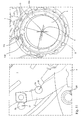
- a longitudinal conveyor 1 can be seen from the front.
- the longitudinal conveyor 1 has frontally a plurality of projecting arms 4, which are rotatably mounted on the longitudinal conveyor 1 and are moved in a rotation of the longitudinal conveyor 1 in the direction of arrow C on a circular path or in the illustrated embodiment on an ellipse.
- the arms 4 are each with recordings 9 and 12 (see also Fig.2 ), which always have a horizontal orientation due to the rotatable mounting of the arms 4.
- the side of the longitudinal conveyor 1 products 3a and 3b are fed to two parallel paths on a format base 2 and taken over in a transfer point I.
- the sequence of movement and the speed of movement of the longitudinal conveyor 1 are designed so that the receptacles 9 and 12 have a speed and direction of movement in the transfer point I, which is identical to the direction of movement and speed of the products 3a and 3b.
- the receptacles 9 and 12 are formed as trough-shaped depressions and acted upon via a vacuum line with a negative pressure.
- the receptacles 9 and 12 are acted upon for receiving the products 3a and 3b with negative pressure, which are then transported by the more negative pressure applied to a transfer point II. Due to the identical speed and direction of movement of the receptacles 9 and 12 in the takeover point I, the products 3 are conveyed away from the format base 2 with the lowest possible forces.
- the arms 4 and the receptacles 9 and 12 arranged thereon exclusively have a vertical speed, which in the direction and the height of the speed provided by first and second lever arms 21 and 20 receptacles 22 and 23 of an in FIG. 2 to be recognized transverse conveyor 7 corresponds.
- the products are in turn passed in the transfer point II by means of compressed air and transported by the cross conveyor 7 in the direction of arrow E to a rotating in the direction of arrow G drum 8.
- the conveyor corresponds to the from DE 41 29 672 A1 known conveying device, which is therefore to add to the understanding of the conveyor expressly added to the disclosure of this application.
- the longitudinal conveyor 1 Since the longitudinal conveyor 1, the products 3, as in the FIG. 2 can be seen, takes over from a longitudinal axial movement and outputs queraxial to the cross conveyor 7, the first arranged parallel in a plane products 3a and 3b in the receptacles 9 and 12 of the cross conveyor 7 transversely to their orientation from the receptacles 9 and 12 taken become. Furthermore, the products 3a and 3b are taken over by a rotating drum 8 in the subsequent transport path, so that the products 3a and 3b must be distributed uniformly over the circumference of the cross conveyor 7 in the transfer point on the drum 8.
- the products 3a and 3b must therefore be evenly distributed out of the plane-parallel alignment present in the longitudinal conveyor 1 on the circumference of the transverse conveyor 7, wherein the product 3b which is farther away from the transverse conveyor 7 has to be moved toward the transverse conveyor 7 via a pivotable first lever arm 21 ,
- the previously fixed receptacles 22 on the second lever arms 20 are now stationary but rotatably carried out.
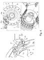
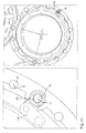
- the transverse conveyor 7 and a section of the longitudinal conveyor 1 can be seen in different angular positions and viewing directions.
- the cross conveyor 7 corresponds in the basic structure of the DE 41 29 672 A1 known transverse conveyor with the difference that the second receptacles 22 are arranged on stationary second lever arms 20, which are each mounted rotatably about the longitudinal axis of the products 3 a received therein. Further, a control lever 19 is provided, which is coupled by not shown intermeshing teeth with two of the second lever arms 20 at the same time.
- the control lever 19 and the first lever arms 21 each engage with their free ends 19a and 21a in cams 14 and 6, wherein the control cam 14, in which engage the control lever 19, is disposed radially inwardly of the control cam 6, in which the first Lever arms 21 engage.
- the cams 6 and 14 are arranged on a fixed control plate 5 concentric with the axis of rotation M of the cross conveyor 7. Due to the rotational movement of the transverse conveyor 7, the ends 19a and 21a of the control lever 19 and the first lever arms 21 in the control cams 14 and 6 run around the axis of rotation M and thereby perform a caused by the individual non-circular shape of the cams 14 and 6 periodic pivotal movement.
- control lever 19 also drives the second lever arms 20 via the interlocking toothings to form a periodic pivoting movement about the longitudinal axis of the channel-shaped second receptacles 22.
- the second receptacles 22 thereby perform a fixed rotational movement, which is defined by the course of the control cam 14 and the lengths of the control lever 19 and the second lever arms 20. Since a control lever 19 is simultaneously coupled to two of the second lever arms 20, only one half of the number of second lever arms 20 corresponding number of control levers 19 is required to control the second lever arms 20, so that the control lever 19 without the risk of self-locking or blockage can be performed in the shorter radially inner cam 14.
- the cross conveyor 7 begins the acquisition of the products 3a and 3b of the longitudinal conveyor 1 with an identical orientation of the adhesive seams 15 and 16.
- the first and second lever arms 21 and 20 are in a position in which the recordings located at their ends 22 and 23 are aligned that the products 3a and 3b are taken over in a plane parallel and horizontally spaced alignment of the receptacles 9 and 12 of the arms 4 of the longitudinal conveyor 1.
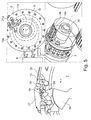
- the first lever arm 21 is pivoted in the direction of arrow H and the control lever 19 in the direction of arrow J.
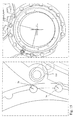
- FIGS. 4 to 9 the positions of the lever arms 20 and 21 can be seen during the further rotational movement of the transverse conveyor 7, wherein the position of the lever arms 20 and 21 in the FIG. 9 a position shortly before the takeover of the products 3a and 3b of the longitudinal conveyor 1, which in the FIG. 3 is shown corresponds.
- FIG. 4 is the cross conveyor 7 in a position after a slight rotation in the direction of arrow K counterclockwise (see left illustration FIG. 3 and 4 ), while the first lever arms 21 straight in the direction of arrow H. be pivoted to the cross conveyor 7 until the products 3b arranged thereon are on a circumference at a constant distance from the pivot point M of the cross conveyor 7 as the products 3a in the receptacles 22 of the second lever arms 20.
- This position is in the FIG. 5 to recognize, which is also characterized in that from this position, the cams 6 and 14 in the further course have a constant distance from the axis of rotation M of the cross conveyor 7, so run arcuate section.
- the lever arms 20 and 21 are not moved in this section, such as in the FIG.
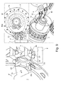
- the alignment of the seams 15 and 16 of the products 3a and 3b should be identical in the transfer point to the hollow drum 8, so that the products 3a and 3b in the further production process, taking into account the uniform alignment of the adhesive seams 15 and 16 provided with a filter and with Tiling paper can be sheathed.
- FIGS. 8 and 9 is the position of the lever arms 20 and 21 to recognize after the transfer of the products 3a and 3b to the hollow drum 8, in which they each in the direction of arrow H and J in the direction of the transfer position of FIG. 3 pivoted to new products 3a and 3b from the longitudinal conveyor 1 to take over.
- FIG. 3 shown position is the pivoting or rotational movement of the first and second lever arms 21 and 20 from the FIG. 3 in the in FIG. 5 shown opposite position.
- the first and second lever arms 21 and 20 thus carry out during the circulation of the transverse conveyor 7 a periodic by the course of the cams 6 and 14 forced rotary or pivotal movement between the takeover and transfer orders.
- the products 3a are doing during the rotational movement of the transverse conveyor 7 from in the FIG. 3 takeover position in the FIG. 7 shown transfer position rotated about its longitudinal axis in a clockwise direction. Since the first lever arms 21 likewise execute a clockwise pivoting movement during this rotary movement of the transverse conveyor 7, the products 3a and 3b are rectilinearly twisted with the adhesive seams 15 and 16, so that the angular difference of the alignment of the adhesive seams 15 and 16 in the transfer point to the hollow drum 8 at least can be reduced.
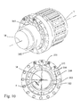
- FIG. 10 an alternative embodiment of the invention can be seen, in which the control device for controlling the movement of the second lever arms 101 is formed by a control ring 100 mounted eccentrically to the axis of rotation M of the transverse conveyor 7.
- the control ring 100 is mounted on a relative to the axis of rotation of a transverse conveyor 7 or a drum trunk 8 fixed bearing bush 102 which may be fixed in itself or rotatably mounted.
- the rotatable mounting of the bearing bush 102 may be advantageous in that it friction losses can be minimized. In the event that the bearing bush 102 is rotatably mounted, this can also be formed integrally with the control ring 100 be.
- a plurality of distributed over the circumference arranged bearing bores 103 are provided, in which the second lever arms 101 are mounted themselves, or in which third lever arms 104 are mounted, which are rotatably coupled at their free ends to the free ends of the second lever arms 101 ,
- the third lever arms 104 thereby form a coupling gear, via which the rotational movement of the second lever arms 101 is controlled.
- the length of the second lever arms 101 and also the length of the third lever arms 104 can be used.
- the degree of eccentricity "e” can be used for the design of the rotational movement of the second lever arms 101, this measure with an adjustment of the eccentricity “e” also a change of the movement after assembly of the cross conveyor 7 without a constructive change of the rest allows parts involved in the movement. Due to the eccentricity "e", the receptacles of the second lever arms 101 indirectly or directly coupled to the control ring 100 produce a rotational movement with a sinusoidal change in angle with respect to the rotational movement of the transverse conveyor 7, wherein the angular range is partly determined by the eccentricity "e” , Further, on the control ring 100 also first lever arms 105 may be provided, which also perform a forced by the control ring 100 pivoting movement, as already to that of the FIGS. 3 to 9 known embodiment has been described, when the control ring 100 is arranged on a transverse conveyor 7.
- the control ring 100 can thus the same function as the two cams 6 and 14 in the in the FIGS. 3 to 9 perceived embodiment and additionally offers the advantage that instead of a plurality of lever arms and control levers now only a part, namely the control ring 100, carries out a shift movement to be stored. As a result, the wear can be reduced and the movement can be made more reliable process by a simplified guide.
- the novel control of the second lever arms 101 via the control ring 100 can also be used to further develop the following bowl drums 8, which takes over the products 3a and 3b from the transverse conveyor 7 or from another drum 8.
- the term division of the receptacles on the drum mills the distance of the receptacles in the circumferential direction of the drum tubules is understood, which can not be changed in a fixed recordings firstly and secondly fixed by the number of distributed over the circumference arranged recordings.
- FIG. 11 In the FIG. 11 is a hollow drum 8 with a respect to this eccentrically mounted control ring 100 can be seen.
- the pivot point "G" of the control ring 100 is offset from the pivot point "D" of the hollow drum 8 eccentrically by the dimension "e”.
- On the control ring 100 a plurality of third lever arms 104 are pivotally mounted, which in turn are coupled to the free ends of first lever arms 101 which are mounted on the drum 8.
- the first lever arms 101 are mounted centrally or at its end on the drum trunk 8 perform the recordings of the first lever arms 101 either pure rotational movements with the advantages described above, or they perform a pivoting movements, by the division of the hollow drum 8 can be changed or set in the transfer and transfer points.
- the products 3 b held in these receptacles can be rotated back as far as the rotation of the drum 8 until the alignment of the adhesive seams 15 and 16 are identical in the transfer point to a subsequent drum or other type of transport device, as in FIG. 14 shown position of the hollow drum 8 can be seen before the transfer of the product 3b to a subsequent bowl drum.
- the first lever arms 101 perform by the eccentric mounting of the control ring 100 an alternating pivotal movement with a sinusoidal change in the angle of rotation of the images arranged thereon. Since the products held in the receptacles of the pivotable first lever arms 101 rotate from the transfer point to the transfer point on a rotation angle of the drum 8 of more than 270 degrees, the direction of movement of the receptacles in the transfer position and the transfer position is rectified. It is important for the inventive success that the difference between the angular positions of the images in the takeover and the transfer point to the angular difference of the acquired products 3a and 3b is identical but opposite. Also, the compensation of the angular offset of the adhesive seams 15 and 16 by the rotatable or pivotable first lever arms 101 on the arranged in the transport path to the cross conveyor 7 hollow drum 8 is explicitly mentioned here as an independent solution to the problem of the invention.
- FIG. 16 shows a further alternative embodiment of the invention, in which the second receptacles 22 are each arranged on a rotatably mounted on the cross conveyor 7 sleeve 202. Further, a rotatably mounted on the transverse conveyor 7 intermediate wheel 203 is provided, which is located at its outer periphery in a force-transmitting connection with the sleeve 202. In addition, a driven by the movement of the first lever arm 21 wheel 201 is provided, which in turn is in force transmitting connection to the intermediate wheel. However, the wheel 201 may also be omitted by the first lever arm 21 drives the intermediate 203 directly.
- the wheel 201 is arranged directly on the first lever arm 21 driving lever shaft, so that the rotational movement is transmitted directly and that with an identical angle of rotation.
- the wheel 201, the intermediate gear 203 and the sleeve 202 may, for example, by gears engage with each other and form a gear 200 through which the pivotal movement of the first lever arm 21 is transmitted to the second receptacle 22, wherein the pivotal movements of the first Lever arm 21 and the second receptacle 22 are rectified by the interposition of the intermediate gear 203.
- no second control cam or other separate control device for controlling the movement of the second images is required.
- the gear ratio of the gear 201 formed by the wheel 201, the intermediate gear 203 and the sleeve 202 in this case defines the angle of rotation of the second receptacle 22 relative to the arranged on the first lever arm 21 first receptacle 23.
- the sleeve 202 can through the second receptacle 22nd yourself or as a substitute be formed by a non-rotatably connected to the second receptacle 22 connected wheel.
- the rotational movement of the second receptacles 22, which is made possible according to the invention, can also be aligned differently to the pivoting direction of the first lever arms 21, so that the stitch plies 15 and 16 are deliberately changed so that they have a more favorable orientation for the further processing process.
- the alignment of at least one of the seam layers 15 and 16 can be rotated so far that in the subsequent processing, an overlap of the seam layers 15 and 16 can be excluded with the seam layer of the subsequently applied document paper. An identical orientation of the suture layers 15 and 16 is therefore no longer necessary.
- the interpretation of the angular relationships of the first receptacles 23 to the second receptacles 22 after the acquisition of the products 3a and 3b can be done in particular by the design of the gearbox geometries and in particular the diameter of the wheels 201, the intermediate gear 203 and the sleeve 202.
Landscapes
- Specific Conveyance Elements (AREA)
- Chain Conveyers (AREA)
Applications Claiming Priority (1)
| Application Number | Priority Date | Filing Date | Title |
|---|---|---|---|
| DE102010053173A DE102010053173A1 (de) | 2010-12-03 | 2010-12-03 | Fördervorrichtung zum Fördern stabförmiger Produkte der Tabak verarbeitenden Industrie |
Publications (2)
| Publication Number | Publication Date |
|---|---|
| EP2460421A1 true EP2460421A1 (fr) | 2012-06-06 |
| EP2460421A9 EP2460421A9 (fr) | 2012-07-18 |
Family
ID=45065774
Family Applications (1)
| Application Number | Title | Priority Date | Filing Date |
|---|---|---|---|
| EP11190692A Withdrawn EP2460421A1 (fr) | 2010-12-03 | 2011-11-25 | Dispositif de transport pour transporter des produits en forme de tige de l'industrie de traitement du tabac |
Country Status (3)
| Country | Link |
|---|---|
| EP (1) | EP2460421A1 (fr) |
| CN (1) | CN102551197A (fr) |
| DE (1) | DE102010053173A1 (fr) |
Cited By (2)
| Publication number | Priority date | Publication date | Assignee | Title |
|---|---|---|---|---|
| EP2478782A3 (fr) * | 2011-01-25 | 2014-09-17 | Hauni Maschinenbau AG | Dispositif de transport pour produits en forme de tige de l'industrie de traitement du tabac |
| CN117068474A (zh) * | 2023-08-30 | 2023-11-17 | 苏州医疗用品厂有限公司 | 一种针灸针新型高速精密排针系统 |
Families Citing this family (1)
| Publication number | Priority date | Publication date | Assignee | Title |
|---|---|---|---|---|
| CN111468843B (zh) * | 2020-03-05 | 2024-11-26 | 江苏瑞驰机电科技有限公司 | 一种细棒物摆臂式传动装置及其配套的激光穿孔机 |
Citations (4)
| Publication number | Priority date | Publication date | Assignee | Title |
|---|---|---|---|---|
| DE4203517A1 (de) * | 1991-02-11 | 1992-08-20 | Gd Spa | Vorrichtung zur ueberfuehrung von zigarettenabschnitten |
| DE4129672A1 (de) | 1991-09-06 | 1993-03-11 | Hauni Werke Koerber & Co Kg | Foerdervorrichtung zum foerdern stabfoermiger artikel der tabakverarbeitenden industrie |
| EP1493338A1 (fr) * | 2003-07-04 | 2005-01-05 | Hauni Maschinenbau AG | Appareil de transport et élément de transfert pour transférer des articles en forme de tige de l'industrie du tabac, du transport de la direction longitudinale vers une direction transversale |
| DE60105907T2 (de) * | 2000-07-21 | 2005-10-06 | G.D Società per Azioni | Einrichtung und Verfahren zur Übertragung von Zigarettenportionen |
Family Cites Families (3)
| Publication number | Priority date | Publication date | Assignee | Title |
|---|---|---|---|---|
| US4121595A (en) * | 1977-02-09 | 1978-10-24 | Hauni-Werke Korber & Co. Kg. | Apparatus for increasing the permeability of wrapping material for rod-shaped smokers products |
| DE10323152A1 (de) * | 2003-05-22 | 2004-12-16 | Hauni Maschinenbau Ag | Vorrichtung zum Messen des Durchmessers eines stabförmigen Gegenstandes insbesondere der Tabak verarbeitenden Industrie |
| DE102004050306B3 (de) * | 2004-10-14 | 2006-06-14 | Hauni Maschinenbau Ag | Einrichtung und Verfahren zum queraxialen Fördern von stabförmigen Artikeln der Tabak verarbeitenden Industrie |
-
2010
- 2010-12-03 DE DE102010053173A patent/DE102010053173A1/de not_active Ceased
-
2011
- 2011-11-25 EP EP11190692A patent/EP2460421A1/fr not_active Withdrawn
- 2011-12-02 CN CN2011103949541A patent/CN102551197A/zh active Pending
Patent Citations (4)
| Publication number | Priority date | Publication date | Assignee | Title |
|---|---|---|---|---|
| DE4203517A1 (de) * | 1991-02-11 | 1992-08-20 | Gd Spa | Vorrichtung zur ueberfuehrung von zigarettenabschnitten |
| DE4129672A1 (de) | 1991-09-06 | 1993-03-11 | Hauni Werke Koerber & Co Kg | Foerdervorrichtung zum foerdern stabfoermiger artikel der tabakverarbeitenden industrie |
| DE60105907T2 (de) * | 2000-07-21 | 2005-10-06 | G.D Società per Azioni | Einrichtung und Verfahren zur Übertragung von Zigarettenportionen |
| EP1493338A1 (fr) * | 2003-07-04 | 2005-01-05 | Hauni Maschinenbau AG | Appareil de transport et élément de transfert pour transférer des articles en forme de tige de l'industrie du tabac, du transport de la direction longitudinale vers une direction transversale |
Cited By (2)
| Publication number | Priority date | Publication date | Assignee | Title |
|---|---|---|---|---|
| EP2478782A3 (fr) * | 2011-01-25 | 2014-09-17 | Hauni Maschinenbau AG | Dispositif de transport pour produits en forme de tige de l'industrie de traitement du tabac |
| CN117068474A (zh) * | 2023-08-30 | 2023-11-17 | 苏州医疗用品厂有限公司 | 一种针灸针新型高速精密排针系统 |
Also Published As
| Publication number | Publication date |
|---|---|
| DE102010053173A1 (de) | 2012-06-06 |
| CN102551197A (zh) | 2012-07-11 |
| EP2460421A9 (fr) | 2012-07-18 |
Similar Documents
| Publication | Publication Date | Title |
|---|---|---|
| EP0994029B1 (fr) | Appareil de génération de mouvements alternatifs | |
| DE2243390C2 (de) | Fördervorrichtung mit Pufferspeicher für Zigaretten | |
| DE2248613A1 (de) | Vorrichtung zum aufkleben von tragschlaufen mittels eines verstaerkungsblattes auf eine voranbewegte bahn beim herstellen von tragbeuteln | |
| EP2258522B1 (fr) | Procédé et dispositif pour couper une tige guidée continûment dans des articles en forme de tige | |
| DE102007049547A1 (de) | Maschine zur Herstellung von zusammengesetzten Filtern | |
| DE3230662C2 (fr) | ||
| EP1639907B1 (fr) | Dispositif de transfert d'articles en forme de tige | |
| DD287464A5 (de) | Einrichtung zum verarbeiten von druckereiprodukten | |
| EP3386293B1 (fr) | Installation de bande transporteuse de volailles | |
| DE102012201915B3 (de) | Längsförderer für stabförmige Produkte der Tabak verarbeitenden Industrie und Fördereinrichtung mit einem Längsförderer und Verfahren zum Betreiben eines Längsförderers | |
| DE4314632C2 (de) | Fördereinrichtung für Gegenstände in Verpackungsmaschinen, insbesondere für Faltschachteln | |
| EP2460421A1 (fr) | Dispositif de transport pour transporter des produits en forme de tige de l'industrie de traitement du tabac | |
| DE2244174A1 (de) | Foerdervorrichtung fuer zigaretten od.dgl | |
| DE3445575A1 (de) | Verfahren zum beabstanden und umdrehen von zwei koaxialen zigarettenlaengenabschnitten an einer maschine zum ansetzen von filtern | |
| DE2718912C2 (fr) | ||
| DE102011009384A1 (de) | Fördervorrichtung für stabförmige Produkte der Tabak verarbeitenden Industrie | |
| EP1423324B1 (fr) | Dispositif de pliage comportant un cylindre a circonference variable | |
| EP1498369B1 (fr) | Dispositif de transport pour transporter d'objets suspendus sur des tringles | |
| DE4307937A1 (de) | Teigteil-Wirkmaschine | |
| EP3338567A1 (fr) | Dispositif de transport rotatif destiné au transport d'articles de l'industrie du traitement du tabac | |
| DE102007050378A1 (de) | Maschine zum Verarbeiten von Druckbogen | |
| EP2803277A1 (fr) | Dispositif de transport pour produits en forme de tige de l'industrie de traitement du tabac | |
| DE2259165A1 (de) | Bogenrotations- druck- und stanzmaschine mit ein- und auskuppelbaren maschineneinheiten | |
| DE2643152B2 (de) | Vorrichtung zum Anordnen eines oder zweier fortlaufender Fäden oder Streifen in einem Zick-zack-Muster auf einer drehbaren Trägerfläche | |
| WO2019007814A1 (fr) | Dispositif de transfert d'articles en forme de tige ainsi qu'arrangement pourvu d'un tel dispositif |
Legal Events
| Date | Code | Title | Description |
|---|---|---|---|
| PUAI | Public reference made under article 153(3) epc to a published international application that has entered the european phase |
Free format text: ORIGINAL CODE: 0009012 |
|
| AK | Designated contracting states |
Kind code of ref document: A1 Designated state(s): AL AT BE BG CH CY CZ DE DK EE ES FI FR GB GR HR HU IE IS IT LI LT LU LV MC MK MT NL NO PL PT RO RS SE SI SK SM TR |
|
| AX | Request for extension of the european patent |
Extension state: BA ME |
|
| 17P | Request for examination filed |
Effective date: 20121204 |
|
| STAA | Information on the status of an ep patent application or granted ep patent |
Free format text: STATUS: THE APPLICATION HAS BEEN WITHDRAWN |
|
| 18W | Application withdrawn |
Effective date: 20141114 |