EP2461023B1 - Pale de rotor pour éolienne et combinaison de station radar et d'éolienne - Google Patents
Pale de rotor pour éolienne et combinaison de station radar et d'éolienne Download PDFInfo
- Publication number
- EP2461023B1 EP2461023B1 EP11009519.7A EP11009519A EP2461023B1 EP 2461023 B1 EP2461023 B1 EP 2461023B1 EP 11009519 A EP11009519 A EP 11009519A EP 2461023 B1 EP2461023 B1 EP 2461023B1
- Authority
- EP
- European Patent Office
- Prior art keywords
- radar
- rotor blade
- thickness
- frequency
- composite fibre
- Prior art date
- Legal status (The legal status is an assumption and is not a legal conclusion. Google has not performed a legal analysis and makes no representation as to the accuracy of the status listed.)
- Active
Links
Images

Classifications
-
- F—MECHANICAL ENGINEERING; LIGHTING; HEATING; WEAPONS; BLASTING
- F03—MACHINES OR ENGINES FOR LIQUIDS; WIND, SPRING, OR WEIGHT MOTORS; PRODUCING MECHANICAL POWER OR A REACTIVE PROPULSIVE THRUST, NOT OTHERWISE PROVIDED FOR
- F03D—WIND MOTORS
- F03D1/00—Wind motors with rotation axis substantially parallel to the air flow entering the rotor
- F03D1/06—Rotors
- F03D1/065—Rotors characterised by their construction elements
- F03D1/0675—Rotors characterised by their construction elements of the blades
-
- F—MECHANICAL ENGINEERING; LIGHTING; HEATING; WEAPONS; BLASTING
- F03—MACHINES OR ENGINES FOR LIQUIDS; WIND, SPRING, OR WEIGHT MOTORS; PRODUCING MECHANICAL POWER OR A REACTIVE PROPULSIVE THRUST, NOT OTHERWISE PROVIDED FOR
- F03D—WIND MOTORS
- F03D80/00—Details, components or accessories not provided for in groups F03D1/00 - F03D17/00
- F03D80/10—Arrangements for warning air traffic
-
- G—PHYSICS
- G01—MEASURING; TESTING
- G01S—RADIO DIRECTION-FINDING; RADIO NAVIGATION; DETERMINING DISTANCE OR VELOCITY BY USE OF RADIO WAVES; LOCATING OR PRESENCE-DETECTING BY USE OF THE REFLECTION OR RERADIATION OF RADIO WAVES; ANALOGOUS ARRANGEMENTS USING OTHER WAVES
- G01S13/00—Systems using the reflection or reradiation of radio waves, e.g. radar systems; Analogous systems using reflection or reradiation of waves whose nature or wavelength is irrelevant or unspecified
- G01S13/02—Systems using reflection of radio waves, e.g. primary radar systems; Analogous systems
- G01S13/50—Systems of measurement based on relative movement of target
- G01S13/52—Discriminating between fixed and moving objects or between objects moving at different speeds
-
- H—ELECTRICITY
- H01—ELECTRIC ELEMENTS
- H01Q—ANTENNAS, i.e. RADIO AERIALS
- H01Q15/00—Devices for reflection, refraction, diffraction or polarisation of waves radiated from an antenna, e.g. quasi-optical devices
- H01Q15/14—Reflecting surfaces; Equivalent structures
- H01Q15/16—Reflecting surfaces; Equivalent structures curved in two dimensions [2D], e.g. paraboloidal
-
- F—MECHANICAL ENGINEERING; LIGHTING; HEATING; WEAPONS; BLASTING
- F05—INDEXING SCHEMES RELATING TO ENGINES OR PUMPS IN VARIOUS SUBCLASSES OF CLASSES F01-F04
- F05B—INDEXING SCHEME RELATING TO WIND, SPRING, WEIGHT, INERTIA OR LIKE MOTORS, TO MACHINES OR ENGINES FOR LIQUIDS COVERED BY SUBCLASSES F03B, F03D AND F03G
- F05B2260/00—Function
- F05B2260/99—Radar absorption
-
- F—MECHANICAL ENGINEERING; LIGHTING; HEATING; WEAPONS; BLASTING
- F05—INDEXING SCHEMES RELATING TO ENGINES OR PUMPS IN VARIOUS SUBCLASSES OF CLASSES F01-F04
- F05B—INDEXING SCHEME RELATING TO WIND, SPRING, WEIGHT, INERTIA OR LIKE MOTORS, TO MACHINES OR ENGINES FOR LIQUIDS COVERED BY SUBCLASSES F03B, F03D AND F03G
- F05B2280/00—Materials; Properties thereof
- F05B2280/60—Properties or characteristics given to material by treatment or manufacturing
- F05B2280/6003—Composites; e.g. fibre-reinforced
-
- Y—GENERAL TAGGING OF NEW TECHNOLOGICAL DEVELOPMENTS; GENERAL TAGGING OF CROSS-SECTIONAL TECHNOLOGIES SPANNING OVER SEVERAL SECTIONS OF THE IPC; TECHNICAL SUBJECTS COVERED BY FORMER USPC CROSS-REFERENCE ART COLLECTIONS [XRACs] AND DIGESTS
- Y02—TECHNOLOGIES OR APPLICATIONS FOR MITIGATION OR ADAPTATION AGAINST CLIMATE CHANGE
- Y02E—REDUCTION OF GREENHOUSE GAS [GHG] EMISSIONS, RELATED TO ENERGY GENERATION, TRANSMISSION OR DISTRIBUTION
- Y02E10/00—Energy generation through renewable energy sources
- Y02E10/70—Wind energy
- Y02E10/72—Wind turbines with rotation axis in wind direction
Definitions
- the present invention relates to a rotor blade for a wind power plant, comprising a shell structure of flat fiber composite material forming the rotor blade surface. Furthermore, the invention relates to a combination of a radar station and a wind turbine arranged in the reception area of the radar station.
- Wind turbines comprise a rotatably mounted rotor structure, which is typically formed by a rotatably mounted rotor shaft, a rotor hub at one end of the rotor shaft and one or more radially projecting from the rotor hub rotor blades (rotor blades).
- the rotor shaft is rotatably mounted about a horizontal axis in a machine housing ("gondola”), which in turn is arranged rotatably about a vertical axis on a vertically towering tower.
- a machine housing gondola
- Such wind turbines generate radar reflections on the tower, on the machine housing and on the rotor structure, in particular the rotor blades, upon irradiation of electromagnetic waves by radar systems.
- the extent of the back reflection of radar radiation at the rotor structure or its rotor blades and the Doppler shift of the radar reflection depend on the direction of incidence of the radar radiation and the rotational position or rotational speed of the rotor structure. In a radar system with moving target detection, which evaluates such Doppler shifts, this may undesirably lead to corresponding parts of the rotor structure, ie z. B. rotor blades are misinterpreted as "flying objects". If in this way wind turbines are imaged on the radar screen of the radar system as an additional target, this can make the recognition of the desired goals sometimes considerably more difficult. Such goals can z. As aircraft in an air surveillance radar, rain clouds in a weather radar or ships in a maritime navigation radar.
- Rotor blades are known from the prior art, which are characterized by radar-absorbing or radar-reflecting structures (see, eg WO 2009/140949 ; WO 2010/122352 ; US 2923934 ).
- This object is achieved by the rotor blade according to claim 1.
- the front edge and the trailing edge of the rotor blade represent those surface sections whose radar reflections have the greatest potential for the operation of radar systems with regard to the Doppler effect.
- the inventive design of the fiber composite material at least in these areas of the shell structure of the rotor blade, namely with a Radarreflexions tint (damping factor) in the frequency range for incident perpendicular to the surface radar radiation has a reflection minimum, a considerable reduction in interference.
- the rotor blade according to the invention may have a basic structure similar to known in the prior art rotor blades, namely z. B. composed of two half-shells, each made of a fiber composite material (eg., Multilayer GRP laminate) are made and glued to each other at the front and rear edges of the rotor blade. Accordingly, it is provided according to an embodiment of the invention that the rotor blade is formed from a plurality of interconnected, in particular glued together shell shells.
- a fiber composite material eg., Multilayer GRP laminate
- two half shells may be provided, which are connected to each other at the front and rear edges of the rotor blade.
- a fiber composite solid material can be a suitable dimensioning rule z.
- d V ⁇ 0 2 ⁇ V
- At least one web which is arranged in the interior of the jacket structure and stabilizes the jacket structure.
- One or more such webs may, for. Example, be formed of sheet-like fiber composite material, which is preferably also designed to provide a frequency-dependent radar reflection factor for incident perpendicular to the surface radar radiation with a reflection minimum at a specific frequency in the range of 1 GHz to 10 GHz.
- the frequency of the radar radiation may be identical or at least substantially identical (eg, less than 10% different than) that frequency for which the fiber composite material at the leading and trailing edges of the rotor blade (and optionally the web or webs) Has reflection minimum.
- the fiber composite material provided for providing the reflection minimum is formed as a fiber composite material.
- this fiber composite material may be formed in sandwich construction comprising a plurality of (identical or different) fiber composite layers.
- z. B. a symmetrical sandwich construction can be used.
- a fiber composite solid material may, for. B. as a laminate comprising a plurality of identical fiber material layers (eg., Weave, braids, scrim, etc.) may be formed.
- a simple sandwich construction sees a core layer z.
- foam plastic in particular hard foam, or wood, especially light wood, or a honeycomb or wave structure (eg., From a resin-impregnated paper or eg a GRP material (eg, containing a glass fiber fabric)), and On both sides thereof arranged cover layers of similar or different types of fiber composite layers (eg., GFRP etc.) before.
- the fiber composite material used to provide said reflection minimum at the leading and trailing edges of the rotor blade particularly preferably has a low electrical conductivity, be it in total (over the entire thickness of the sheath structure) or at least in a near-surface and thus the surface at the leading and trailing edge forming Area.
- a construction reduces the reflection of incident radar energy.
- most of the radar energy is passed through the shell structure of the rotor blade. In this way, the rotor blade is quasi more or less transparent for a large part of the incident radar energy, so that only a relatively small proportion of energy from the rotor blade to the radar system are reflected back, which further reduces the interference of the radar operation.
- fiber composite materials preferred for forming the sheath structure at least at the leading and trailing edges of the rotor blade and / or for forming the stabilizing web (s) are those which conduct electricity poorly (eg materials having an electrical loss factor "tan ⁇ "). less than 0.01) or as electrical non-conductors (e.g. B. materials with an electrical loss factor "tan ⁇ of less than 0.001) are to be regarded.
- a fiber material consisting of electrically non-conductive fibers such.
- electrically non-conductive fibers such as glass fibers, aramid fibers, polyethylene fibers, etc. are used, this in conjunction with an electrically non-conductive matrix such.
- epoxy resin polyester resin, etc.
- individual layers can also z. B. may be formed from the aforementioned rigid foams, etc.
- the "first layer" of the flat fiber composite material which is thus hit directly by the incident radar radiation, is formed from an electrically poor or non-conductive fiber composite material.
- CFK is here due to its relatively high electrical conductivity rather unfavorable, and instead z.
- fiberglass to prefer.
- the "geometry" of the flat fiber composite material used to form the leading and trailing edges of the rotor blade (or of the web or webs) is of great importance.
- this fiber composite material is formed as a fiber composite solid material, as well as when this fiber composite material is formed in sandwich construction comprising a plurality of fiber composite layers, there are always several interfaces between viewed in Radarstrahlungsraum immediately adjacent material layers or between such a material layer and air (on the outside or the inside of the shell structure of the rotor blade).
- the invention provided reflection minimum can be realized in a simple manner that the radar radiation components reflected back from the various interfaces substantially destructive interfere.
- suitable material combinations or material arrangements can, for. B., taking into account the above-described "sizing" are set.
- the above formulas given values for the thickness of a solid material (d V ) and the thickness of the core material (d K ) in a symmetrical sandwich construction are preferably at least approximately provided, for. B. with a deviation between the actual thickness and the given formula given thickness of less than 10%, in particular less than 5%, in the relevant material (fiber composite solid material or core material) resulting wavelength of the radar radiation.
- the fiber composite material provided for providing the reflection minimum has an electrical surface resistivity of more than 10 3 ohms / square.
- the reflection minimum has a value of less than -20 dB, in particular less than -25 dB.
- the reflection minimum has a value of less than -20 dB, in particular less than -25 dB.
- the position of the reflection minimum provided according to the invention is to be adapted as precisely as possible to the frequency of the radar radiation to be expected in the use of the rotor blade. If the frequency of the reflection minimum deviates appreciably from this radar frequency, the radar frequency is still preferably within the half-width of the reflection minimum.
- the frequency-dependent reflection factor in the frequency range from 1 GHz to 10 GHz has exactly one minimum.
- more than a minimum of the reflection factor may be provided in this frequency range, in particular z. B. exactly two minima. In the latter case, the location of the two minima z. B. be adapted to two different radar frequencies of two different radar systems (eg., An air surveillance radar and a weather radar).
- a combination (at least) of a radar station and a wind turbine disposed in the receiving area of the radar station wherein rotor blades of the wind turbine are each formed as a rotor blade according to one of claims 1-3 the frequency of the reflection minimum corresponds to the radar frequency of the radar station.
- Any deviation between the frequency of the reflection minimum and the radar frequency is preferably less than 0.5 GHz.
- the reflection factor at the radar frequency is preferably less than -15 dB, more preferably less than -20 dB.
- the combination comprises two radar stations with mutually different radar frequencies, z.
- the created with the fiber composite frequency-dependent radar reflection factor has two reflection minima of the type explained, the frequencies of which correspond to the radar frequencies of the radar stations. This possibly again with at most rather small deviations, as already described for the case of a radar station and a reflection minimum.
- Each radar station may in particular be a radar station with moving-target detection by evaluating a Doppler shift of the back-reflected radar signal.
- the combination comprises a plurality of radar stations with mutually different radar frequencies
- at least one frequency pair exists among the radar frequencies, in which one radar frequency is an integer multiple of the other radar frequency.
- An example of this is an air traffic control radar with a radar frequency of 3 GHz in combination with a maritime navigation radar with a radar frequency of 9 GHz.
- Fig. 1 illustrates in a sectional view the structure of a rotor blade 10 for a wind turbine, comprising a shell structure 12 and a shell structure 12 stabilizing internal structure 14, which in the illustrated embodiment is formed by two transverse to the direction of extension of the rotor blade profile webs 14-1 and 14-2.
- the rotor blade 10 has a front edge 16 and a rear edge 18.
- the outside of the shell structure 12 defines the surface 20 of the rotor blade 10 and the shell structure 12 is formed of flat fiber composite material, wherein in the illustrated embodiment, two different areas or different fiber composite materials 12-1 and 12-2 are used.
- the material is 12-1 is used to form the leading edge 16 and the adjoining shell structure areas to about the center of the illustrated rotor blade 10 (beyond the webs 14-1, 14-2).
- the material 12-2 is provided to form the underlying areas of the rotor blade 10 up to the trailing edge 18.
- the webs 14-1, 14-2 are each formed of (identical) fiber composite material, which, however, differs from the flat fiber composite materials 12-1 and 12-2.
- a special feature of the rotor blade 10 is that at least at the front edge 16 and the trailing edge 18, in the example shown in the region of the webs 14-1, 14-2, the respective fiber composite material 12-1 and 12-2 (and in the example shown Also, the fiber composite materials 14-1, 14-2) is designed to provide a frequency-dependent radar reflection factor R for perpendicular to the surface incident electromagnetic radar radiation with a reflection minimum at a specific frequency in the range of 1 GHz to 10 GHz.
- Fig. 2, 3 and 4 show the respective constructions of the flat fiber composite materials 12-1, 12-2 and 14-1, 14-2, respectively.
- the fiber composite material 12-1 ( Fig. 2 ) has a monolithic GRP construction, ie consists of a layer of GRP material, with a thickness of 12.9 mm.
- the dielectric constant of the GFRP material 12-1 is about 4.3.
- the fiber composite material 12-2 ( Fig. 3 ) is a sandwich construction of an outer GRP cover layer 22 (thickness 1 mm, dielectric constant 4.3), an inner GRP cover layer 24 (thickness 1 mm, dielectric constant 4.3), and a hard foam core 26 (thickness 11.3 mm, dielectric constant 1.1).
- the fiber composite material 14-1, 14-2 (FIG. Fig. 4 ) is also a sandwich construction of an outer GRP cover layer 22 '(thickness 2 mm, dielectric constant 4.3), an inner GRP cover layer 24' (thickness 2 mm, dielectric constant 4.3), and a hard foam core 26 '( Thickness 8.5 mm, dielectric constant 1.1).
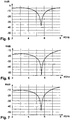
- FIGS. 5, 6 and 7 are the calculated frequency - dependent reflection factor curves in the Fig. 2, 3 and 4 represented fiber composite materials at normal incidence of radiation.
- Fig. 5 shows the reflection factor R for the fiber composite material 12-1.
- Fig. 6 shows the reflection factor R for the fiber composite material 12-2.
- Fig. 7 shows the reflection factor R for the fiber composite 14-1, 14-2.
- the half-value widths of the reflection minima lying at 5.6 GHz are each less than 0.5 GHz.
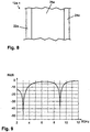
- Fig. 8 illustrates another example of a construction suitable for reducing radar reflections and shows a sectional view of a sheet-like fiber composite material 12a-1.
- the fiber composite material 12a-1 may, for. B. in a rotor blade of Fig. 1 shown type as a substitute for one or more of the fiber composite materials used there 12-1, 12-2 and 14-1, 14-2 are used.
- the in Fig. 8 represented fiber composite material 12a-1 for the entire shell structure (and the optionally provided internal structure) of such a rotor blade of in Fig. 1 used type shown.
- the fiber composite material 12a-1 is a sandwich construction of an outer GRP cover layer 22a (thickness 3 mm, dielectric constant 4.3), an inner GRP cover layer 24a (thickness 3 mm, dielectric constant 4.3), and a honeycomb core 26 '. made of resin-impregnated paper (thickness 17.5 mm, dielectric constant 1.07).
- a special feature of the fiber composite material 12a-1 is that its frequency-dependent radar reflection factor R for radar radiation incident perpendicular to the surface has two reflection minima at certain frequencies in the range of 1 GHz to 10 GHz.
- these reflection minima are at the frequencies of 3 GHz (eg frequency of a military air traffic control radar) and at 9 GHz (eg frequency of a maritime navigation radar). At these frequencies, a significant reduction in radar reflectivity is achieved, namely at 0.001% (at 3 GHz) and 0.02% (at 9 GHz).
- a rotor blade for a wind turbine can be realized in which the radar reflections are significantly reduced.
- the reflection-minimized fiber composite material is used at least at the leading edge and the trailing edge of the rotor blade.
- Radar frequencies can be adapted to the particular arrangement and combination of materials and their dimensions, layer thickness (s) and electromagnetic material constants.
- metallic conductors must be provided to z. B. from the rotor blade tip or the rotor blade surface lightning currents in the direction of the earth (eg., Via a machine housing and a tower) to dissipate.
- epoxy resin as the matrix is often preferred in the fiber composite materials described, other matrix materials such. As thermoplastics in question.
Landscapes
- Engineering & Computer Science (AREA)
- Radar, Positioning & Navigation (AREA)
- Remote Sensing (AREA)
- Physics & Mathematics (AREA)
- Chemical & Material Sciences (AREA)
- Combustion & Propulsion (AREA)
- Mechanical Engineering (AREA)
- General Engineering & Computer Science (AREA)
- Life Sciences & Earth Sciences (AREA)
- Sustainable Energy (AREA)
- Sustainable Development (AREA)
- Computer Networks & Wireless Communication (AREA)
- General Physics & Mathematics (AREA)
- Electromagnetism (AREA)
- Radar Systems Or Details Thereof (AREA)
- Wind Motors (AREA)
Claims (4)
- Pale de rotor (10) pour éolienne, comprenant une structure d'enveloppe en matériau composite fibreux plat (12-1, 12-2) formant la surface de pale de rotor (20), le matériau composite fibreux (12-1, 12-2) étant conçu au moins sur le bord d'attaque (16) et le bord de fuite (18) de la pale de rotor (10) pour créer un facteur de réflexion radar (R) dépendant de la fréquence pour un rayonnement radar d'incidence perpendiculaire à la surface avec un minimum de réflexion à une fréquence comprise entre 1 GHz et 10 GHz ;
le matériau composite fibreux (12-1, 12-2) prévu pour l'obtention du minimum de réflexion étant réalisé sous la forme d'un matériau plein en matière composite fibreuse (12-1) et l'épaisseur (dV) du matériau plein en matière composite fibreuse (12-1) possédant au moins approximativement une valeur de dV désigne l'épaisseur du matériau plein (12-1),λ0 désigne la longueur d'onde en espace libre du rayonnement radar, etεV désigne la constante diélectrique spécifique (partie réelle) du matériau plein ;ou le matériau composite fibreux (12-1, 12-2) prévu pour l'obtention du minimum de réflexion étant réalisé en une construction en sandwich (12-2) symétrique avec deux couches de matière composite fibreuse (22, 24) comme couches extérieures et une couche de matériau d'âme (26) et l'épaisseur (dK) de la couche de matériau d'âme (26) possédant au moins approximativement une valeur de
 dK désigne l'épaisseur de la couche de matériau d'âme (26),λ0 désigne la longueur d'onde en espace libre du rayonnement radar,εK désigne la constante diélectrique spécifique (partie réelle) du matériau d'âme,dD désigne l'épaisseur des couches extérieures (22, 24), etεD désigne la constante diélectrique spécifique (partie réelle) du matériau de couche extérieure ;et
le matériau composite fibreux (12-1 ; 22, 24, 26) prévu pour l'obtention du minimum de réflexion présentant une résistance électrique superficielle spécifique de plus de 103 ohms/carré. - Pale de rotor selon l'une des revendications précédentes, dans laquelle le minimum de réflexion possède une valeur inférieure à -20 dB, en particulier inférieure à -25 dB.
- Pale de rotor selon l'une des revendications précédentes, dans laquelle le facteur de réflexion (R) dépendant de la fréquence dans la plage de fréquence de 1 GHz à 10 GHz possède exactement un minimum ou exactement deux minimums.
- Combinaison d'une station radar et d'une éolienne disposée dans la zone de réception de la station radar, caractérisée en ce que des pales de rotor de l'éolienne sont réalisées respectivement sous la forme d'une pale de rotor (10) selon l'une des revendications 1 à 3, la fréquence du minimum de réflexion correspondant à la fréquence radar de la station radar.
Applications Claiming Priority (1)
| Application Number | Priority Date | Filing Date | Title |
|---|---|---|---|
| DE102010053369A DE102010053369A1 (de) | 2010-12-03 | 2010-12-03 | Rotorblatt für eine Windenergieanlage, sowie Kombination einer Radarstation und einer Windenergieanlage |
Publications (3)
| Publication Number | Publication Date |
|---|---|
| EP2461023A2 EP2461023A2 (fr) | 2012-06-06 |
| EP2461023A3 EP2461023A3 (fr) | 2016-10-26 |
| EP2461023B1 true EP2461023B1 (fr) | 2018-03-07 |
Family
ID=45315410
Family Applications (1)
| Application Number | Title | Priority Date | Filing Date |
|---|---|---|---|
| EP11009519.7A Active EP2461023B1 (fr) | 2010-12-03 | 2011-12-02 | Pale de rotor pour éolienne et combinaison de station radar et d'éolienne |
Country Status (7)
| Country | Link |
|---|---|
| US (1) | US9062658B2 (fr) |
| EP (1) | EP2461023B1 (fr) |
| CN (1) | CN102606384A (fr) |
| BR (1) | BRPI1106916A2 (fr) |
| DE (1) | DE102010053369A1 (fr) |
| DK (1) | DK2461023T3 (fr) |
| ES (1) | ES2672896T3 (fr) |
Families Citing this family (2)
| Publication number | Priority date | Publication date | Assignee | Title |
|---|---|---|---|---|
| GB2484941A (en) * | 2010-10-26 | 2012-05-02 | Vestas Wind Sys As | Material with radar absorbing circuit analogue elements for surface application to a wind turbine component |
| CN106845018B (zh) * | 2017-02-27 | 2020-06-16 | 中国民航大学 | 风电场对气象雷达降雨量影响的分析与定量化评估方法 |
Family Cites Families (14)
| Publication number | Priority date | Publication date | Assignee | Title |
|---|---|---|---|---|
| US2923934A (en) * | 1945-03-05 | 1960-02-02 | Method and means for minimizing reflec- | |
| US5474837A (en) * | 1994-01-21 | 1995-12-12 | The United States Government As Represented By The Secretary Of The Army | Laminated paper glass camouflage |
| JP2001196782A (ja) * | 2000-01-12 | 2001-07-19 | Toyo Chem Co Ltd | 電磁波吸収体 |
| JP2006114877A (ja) | 2004-09-15 | 2006-04-27 | Suzuki Sogyo Co Ltd | 電磁波吸収シート、電磁波吸収シート積層体及びそれらを用いた電磁波吸収性ハウジング |
| KR20090027379A (ko) * | 2007-09-12 | 2009-03-17 | 재단법인서울대학교산학협력재단 | 전자파 차폐 프리프레그 구조체와 이를 이용한 안테나 |
| FR2930601B1 (fr) * | 2008-04-24 | 2010-05-28 | Ineo Defense | Pale d'eolienne furtive et eolienne munie d'une telle pale |
| DE102008024644B4 (de) * | 2008-05-21 | 2018-07-26 | Airbus Defence and Space GmbH | Rotorblatt mit darin integriertem Radarabsorber für eine Windkraftanlage |
| GB0905312D0 (en) * | 2009-03-27 | 2009-05-13 | Qinetiq Ltd | Electromagnetic field absorbing composition |
| GB0907010D0 (en) * | 2009-04-23 | 2009-06-03 | Vestas Wind Sys As | Improvements in or relating to composite structures |
| GB0907011D0 (en) * | 2009-04-23 | 2009-06-03 | Vestas Wind Sys As | Incorporation of functional cloth into prepeg composites |
| GB0907009D0 (en) * | 2009-04-23 | 2009-06-03 | Vestas Wind Sys As | Improvements in or relating to composite structures |
| GB2473020B (en) * | 2009-08-27 | 2012-02-01 | Vestas Wind Sys As | Wind turbine composite structures |
| GB0919198D0 (en) * | 2009-11-02 | 2009-12-16 | Qinetiq Ltd | Wind turbine blades |
| GB2480064A (en) * | 2010-05-04 | 2011-11-09 | Vestas Wind Sys As | RAM panel arrangements for a wind turbine tower |
-
2010
- 2010-12-03 DE DE102010053369A patent/DE102010053369A1/de not_active Withdrawn
-
2011
- 2011-12-02 EP EP11009519.7A patent/EP2461023B1/fr active Active
- 2011-12-02 CN CN2011104111832A patent/CN102606384A/zh active Pending
- 2011-12-02 US US13/310,086 patent/US9062658B2/en active Active
- 2011-12-02 DK DK11009519.7T patent/DK2461023T3/en active
- 2011-12-02 ES ES11009519.7T patent/ES2672896T3/es active Active
- 2011-12-05 BR BRPI1106916-3A patent/BRPI1106916A2/pt not_active IP Right Cessation
Non-Patent Citations (1)
| Title |
|---|
| None * |
Also Published As
| Publication number | Publication date |
|---|---|
| EP2461023A3 (fr) | 2016-10-26 |
| US9062658B2 (en) | 2015-06-23 |
| DK2461023T3 (en) | 2018-06-18 |
| ES2672896T3 (es) | 2018-06-18 |
| BRPI1106916A2 (pt) | 2013-03-26 |
| US20120141285A1 (en) | 2012-06-07 |
| DE102010053369A1 (de) | 2012-02-16 |
| EP2461023A2 (fr) | 2012-06-06 |
| CN102606384A (zh) | 2012-07-25 |
Similar Documents
| Publication | Publication Date | Title |
|---|---|---|
| EP2297815B1 (fr) | Pale de rotor d'éolienne pourvue d'un absorbeur radar intégré | |
| KR101779773B1 (ko) | 풍력 터빈 블레이드 | |
| EP4009440B1 (fr) | Paroi de radôme pour les applications de communication | |
| EP2632697B1 (fr) | Âme pour structure composite et methode de fabrication correspondante | |
| DE102012217904A1 (de) | Faserverbundbauteil und Rotorblatt | |
| DE1274686B (de) | Radarantenne in Form einer Rechteckhohlleiter-Schlitzantenne fuer ein Drehfluegelflugzeug | |
| DE102013100117B4 (de) | Windkraftanlagen-Rotorblätter mit verringerten Radarquerschnitten | |
| DE102011076501A1 (de) | Abdeckung für einen radarsensor | |
| EP4064454A1 (fr) | Radôme de conception asymétrique | |
| EP2461023B1 (fr) | Pale de rotor pour éolienne et combinaison de station radar et d'éolienne | |
| EP2747202A1 (fr) | Paroi d'un radôme | |
| DE3821588C1 (de) | Flügelblatt mit schwachem Radarecho | |
| DE69619153T2 (de) | Verbundwerkstoffstruktur, fähig zur Absorption und Dissipation von auffallender elektromagnetischer Strahlungsenergie, insbesondere für Luft-, See- und Landfahrzeuge und für feste Bodeneinrichtungen | |
| DE112020007455T5 (de) | Blitzschutzsystem für ein modulares rotorblatt und verfahren zur herstellung eines stapels | |
| EP2708740A1 (fr) | Pale de rotor d'éolienne avec un dispositif de chauffage électrique et un paratonnerre | |
| EP2485329B1 (fr) | Antenne groupée | |
| EP0378838A1 (fr) | Procédé de réduction de la rétrodiffusion de radiation électromagnétique issue de structures à cavités ouvertes d'un côté | |
| DE19902511C2 (de) | Verkleidungen für Richtfunkantennen | |
| DE202011051341U1 (de) | Stegformation im Rotorblatttip | |
| EP3851371A1 (fr) | Structure de bord avant pour une surface aérodynamique d'un aéronef | |
| DE29816114U1 (de) | Abdeckung für Richtfunkantennen | |
| EP0443564A2 (fr) | Absorbeur pour ondes électromagnétiques | |
| DE2519986C3 (de) | MeBhilfseinrichtung für Radargeräte mit Empfangs- und Rücksendeantenne zum Simulieren entfernter Zielobjekte | |
| EP4214800A1 (fr) | Radôme de protection contre intempéries | |
| EP3992073B1 (fr) | Appareil téléscopique pour un sous-marin |
Legal Events
| Date | Code | Title | Description |
|---|---|---|---|
| PUAI | Public reference made under article 153(3) epc to a published international application that has entered the european phase |
Free format text: ORIGINAL CODE: 0009012 |
|
| AK | Designated contracting states |
Kind code of ref document: A2 Designated state(s): AL AT BE BG CH CY CZ DE DK EE ES FI FR GB GR HR HU IE IS IT LI LT LU LV MC MK MT NL NO PL PT RO RS SE SI SK SM TR |
|
| AX | Request for extension of the european patent |
Extension state: BA ME |
|
| RAP1 | Party data changed (applicant data changed or rights of an application transferred) |
Owner name: AIRBUS DEFENCE AND SPACE GMBH |
|
| PUAL | Search report despatched |
Free format text: ORIGINAL CODE: 0009013 |
|
| AK | Designated contracting states |
Kind code of ref document: A3 Designated state(s): AL AT BE BG CH CY CZ DE DK EE ES FI FR GB GR HR HU IE IS IT LI LT LU LV MC MK MT NL NO PL PT RO RS SE SI SK SM TR |
|
| AX | Request for extension of the european patent |
Extension state: BA ME |
|
| RIC1 | Information provided on ipc code assigned before grant |
Ipc: H01Q 15/16 20060101ALI20160919BHEP Ipc: F03D 11/00 00000000ALI20160919BHEP Ipc: F03D 1/06 20060101AFI20160919BHEP Ipc: G01S 13/52 20060101ALI20160919BHEP |
|
| STAA | Information on the status of an ep patent application or granted ep patent |
Free format text: STATUS: REQUEST FOR EXAMINATION WAS MADE |
|
| 17P | Request for examination filed |
Effective date: 20170421 |
|
| RIC1 | Information provided on ipc code assigned before grant |
Ipc: F03D 80/00 20160101ALI20170905BHEP Ipc: G01S 13/52 20060101ALI20170905BHEP Ipc: H01Q 15/16 20060101ALI20170905BHEP Ipc: F03D 1/06 20060101AFI20170905BHEP Ipc: F03D 80/10 20160101ALI20170905BHEP |
|
| GRAP | Despatch of communication of intention to grant a patent |
Free format text: ORIGINAL CODE: EPIDOSNIGR1 |
|
| STAA | Information on the status of an ep patent application or granted ep patent |
Free format text: STATUS: GRANT OF PATENT IS INTENDED |
|
| INTG | Intention to grant announced |
Effective date: 20171110 |
|
| GRAS | Grant fee paid |
Free format text: ORIGINAL CODE: EPIDOSNIGR3 |
|
| GRAA | (expected) grant |
Free format text: ORIGINAL CODE: 0009210 |
|
| STAA | Information on the status of an ep patent application or granted ep patent |
Free format text: STATUS: THE PATENT HAS BEEN GRANTED |
|
| AK | Designated contracting states |
Kind code of ref document: B1 Designated state(s): AL AT BE BG CH CY CZ DE DK EE ES FI FR GB GR HR HU IE IS IT LI LT LU LV MC MK MT NL NO PL PT RO RS SE SI SK SM TR |
|
| REG | Reference to a national code |
Ref country code: GB Ref legal event code: FG4D Free format text: NOT ENGLISH |
|
| REG | Reference to a national code |
Ref country code: CH Ref legal event code: EP Ref country code: AT Ref legal event code: REF Ref document number: 976843 Country of ref document: AT Kind code of ref document: T Effective date: 20180315 |
|
| REG | Reference to a national code |
Ref country code: IE Ref legal event code: FG4D Free format text: LANGUAGE OF EP DOCUMENT: GERMAN |
|
| REG | Reference to a national code |
Ref country code: DE Ref legal event code: R096 Ref document number: 502011013846 Country of ref document: DE |
|
| REG | Reference to a national code |
Ref country code: ES Ref legal event code: FG2A Ref document number: 2672896 Country of ref document: ES Kind code of ref document: T3 Effective date: 20180618 Ref country code: DK Ref legal event code: T3 Effective date: 20180611 |
|
| REG | Reference to a national code |
Ref country code: NL Ref legal event code: FP |
|
| REG | Reference to a national code |
Ref country code: LT Ref legal event code: MG4D |
|
| PG25 | Lapsed in a contracting state [announced via postgrant information from national office to epo] |
Ref country code: LT Free format text: LAPSE BECAUSE OF FAILURE TO SUBMIT A TRANSLATION OF THE DESCRIPTION OR TO PAY THE FEE WITHIN THE PRESCRIBED TIME-LIMIT Effective date: 20180307 Ref country code: HR Free format text: LAPSE BECAUSE OF FAILURE TO SUBMIT A TRANSLATION OF THE DESCRIPTION OR TO PAY THE FEE WITHIN THE PRESCRIBED TIME-LIMIT Effective date: 20180307 Ref country code: NO Free format text: LAPSE BECAUSE OF FAILURE TO SUBMIT A TRANSLATION OF THE DESCRIPTION OR TO PAY THE FEE WITHIN THE PRESCRIBED TIME-LIMIT Effective date: 20180607 Ref country code: FI Free format text: LAPSE BECAUSE OF FAILURE TO SUBMIT A TRANSLATION OF THE DESCRIPTION OR TO PAY THE FEE WITHIN THE PRESCRIBED TIME-LIMIT Effective date: 20180307 Ref country code: CY Free format text: LAPSE BECAUSE OF FAILURE TO SUBMIT A TRANSLATION OF THE DESCRIPTION OR TO PAY THE FEE WITHIN THE PRESCRIBED TIME-LIMIT Effective date: 20180307 |
|
| PG25 | Lapsed in a contracting state [announced via postgrant information from national office to epo] |
Ref country code: SE Free format text: LAPSE BECAUSE OF FAILURE TO SUBMIT A TRANSLATION OF THE DESCRIPTION OR TO PAY THE FEE WITHIN THE PRESCRIBED TIME-LIMIT Effective date: 20180307 Ref country code: LV Free format text: LAPSE BECAUSE OF FAILURE TO SUBMIT A TRANSLATION OF THE DESCRIPTION OR TO PAY THE FEE WITHIN THE PRESCRIBED TIME-LIMIT Effective date: 20180307 Ref country code: GR Free format text: LAPSE BECAUSE OF FAILURE TO SUBMIT A TRANSLATION OF THE DESCRIPTION OR TO PAY THE FEE WITHIN THE PRESCRIBED TIME-LIMIT Effective date: 20180608 Ref country code: BG Free format text: LAPSE BECAUSE OF FAILURE TO SUBMIT A TRANSLATION OF THE DESCRIPTION OR TO PAY THE FEE WITHIN THE PRESCRIBED TIME-LIMIT Effective date: 20180607 Ref country code: RS Free format text: LAPSE BECAUSE OF FAILURE TO SUBMIT A TRANSLATION OF THE DESCRIPTION OR TO PAY THE FEE WITHIN THE PRESCRIBED TIME-LIMIT Effective date: 20180307 |
|
| PG25 | Lapsed in a contracting state [announced via postgrant information from national office to epo] |
Ref country code: MT Free format text: LAPSE BECAUSE OF FAILURE TO SUBMIT A TRANSLATION OF THE DESCRIPTION OR TO PAY THE FEE WITHIN THE PRESCRIBED TIME-LIMIT Effective date: 20180307 |
|
| PG25 | Lapsed in a contracting state [announced via postgrant information from national office to epo] |
Ref country code: IT Free format text: LAPSE BECAUSE OF FAILURE TO SUBMIT A TRANSLATION OF THE DESCRIPTION OR TO PAY THE FEE WITHIN THE PRESCRIBED TIME-LIMIT Effective date: 20180307 Ref country code: AL Free format text: LAPSE BECAUSE OF FAILURE TO SUBMIT A TRANSLATION OF THE DESCRIPTION OR TO PAY THE FEE WITHIN THE PRESCRIBED TIME-LIMIT Effective date: 20180307 Ref country code: PL Free format text: LAPSE BECAUSE OF FAILURE TO SUBMIT A TRANSLATION OF THE DESCRIPTION OR TO PAY THE FEE WITHIN THE PRESCRIBED TIME-LIMIT Effective date: 20180307 Ref country code: EE Free format text: LAPSE BECAUSE OF FAILURE TO SUBMIT A TRANSLATION OF THE DESCRIPTION OR TO PAY THE FEE WITHIN THE PRESCRIBED TIME-LIMIT Effective date: 20180307 Ref country code: RO Free format text: LAPSE BECAUSE OF FAILURE TO SUBMIT A TRANSLATION OF THE DESCRIPTION OR TO PAY THE FEE WITHIN THE PRESCRIBED TIME-LIMIT Effective date: 20180307 |
|
| PG25 | Lapsed in a contracting state [announced via postgrant information from national office to epo] |
Ref country code: SM Free format text: LAPSE BECAUSE OF FAILURE TO SUBMIT A TRANSLATION OF THE DESCRIPTION OR TO PAY THE FEE WITHIN THE PRESCRIBED TIME-LIMIT Effective date: 20180307 Ref country code: CZ Free format text: LAPSE BECAUSE OF FAILURE TO SUBMIT A TRANSLATION OF THE DESCRIPTION OR TO PAY THE FEE WITHIN THE PRESCRIBED TIME-LIMIT Effective date: 20180307 Ref country code: SK Free format text: LAPSE BECAUSE OF FAILURE TO SUBMIT A TRANSLATION OF THE DESCRIPTION OR TO PAY THE FEE WITHIN THE PRESCRIBED TIME-LIMIT Effective date: 20180307 |
|
| REG | Reference to a national code |
Ref country code: DE Ref legal event code: R097 Ref document number: 502011013846 Country of ref document: DE |
|
| PG25 | Lapsed in a contracting state [announced via postgrant information from national office to epo] |
Ref country code: PT Free format text: LAPSE BECAUSE OF FAILURE TO SUBMIT A TRANSLATION OF THE DESCRIPTION OR TO PAY THE FEE WITHIN THE PRESCRIBED TIME-LIMIT Effective date: 20180709 |
|
| PLBE | No opposition filed within time limit |
Free format text: ORIGINAL CODE: 0009261 |
|
| STAA | Information on the status of an ep patent application or granted ep patent |
Free format text: STATUS: NO OPPOSITION FILED WITHIN TIME LIMIT |
|
| 26N | No opposition filed |
Effective date: 20181210 |
|
| PG25 | Lapsed in a contracting state [announced via postgrant information from national office to epo] |
Ref country code: SI Free format text: LAPSE BECAUSE OF FAILURE TO SUBMIT A TRANSLATION OF THE DESCRIPTION OR TO PAY THE FEE WITHIN THE PRESCRIBED TIME-LIMIT Effective date: 20180307 |
|
| REG | Reference to a national code |
Ref country code: CH Ref legal event code: PL |
|
| GBPC | Gb: european patent ceased through non-payment of renewal fee |
Effective date: 20181202 |
|
| PG25 | Lapsed in a contracting state [announced via postgrant information from national office to epo] |
Ref country code: MC Free format text: LAPSE BECAUSE OF FAILURE TO SUBMIT A TRANSLATION OF THE DESCRIPTION OR TO PAY THE FEE WITHIN THE PRESCRIBED TIME-LIMIT Effective date: 20180307 Ref country code: LU Free format text: LAPSE BECAUSE OF NON-PAYMENT OF DUE FEES Effective date: 20181202 |
|
| REG | Reference to a national code |
Ref country code: IE Ref legal event code: MM4A |
|
| REG | Reference to a national code |
Ref country code: BE Ref legal event code: MM Effective date: 20181231 |
|
| PG25 | Lapsed in a contracting state [announced via postgrant information from national office to epo] |
Ref country code: IE Free format text: LAPSE BECAUSE OF NON-PAYMENT OF DUE FEES Effective date: 20181202 |
|
| PG25 | Lapsed in a contracting state [announced via postgrant information from national office to epo] |
Ref country code: BE Free format text: LAPSE BECAUSE OF NON-PAYMENT OF DUE FEES Effective date: 20181231 |
|
| PG25 | Lapsed in a contracting state [announced via postgrant information from national office to epo] |
Ref country code: GB Free format text: LAPSE BECAUSE OF NON-PAYMENT OF DUE FEES Effective date: 20181202 Ref country code: CH Free format text: LAPSE BECAUSE OF NON-PAYMENT OF DUE FEES Effective date: 20181231 Ref country code: LI Free format text: LAPSE BECAUSE OF NON-PAYMENT OF DUE FEES Effective date: 20181231 |
|
| REG | Reference to a national code |
Ref country code: AT Ref legal event code: MM01 Ref document number: 976843 Country of ref document: AT Kind code of ref document: T Effective date: 20181202 |
|
| PG25 | Lapsed in a contracting state [announced via postgrant information from national office to epo] |
Ref country code: TR Free format text: LAPSE BECAUSE OF FAILURE TO SUBMIT A TRANSLATION OF THE DESCRIPTION OR TO PAY THE FEE WITHIN THE PRESCRIBED TIME-LIMIT Effective date: 20180307 |
|
| PG25 | Lapsed in a contracting state [announced via postgrant information from national office to epo] |
Ref country code: AT Free format text: LAPSE BECAUSE OF NON-PAYMENT OF DUE FEES Effective date: 20181202 |
|
| PG25 | Lapsed in a contracting state [announced via postgrant information from national office to epo] |
Ref country code: HU Free format text: LAPSE BECAUSE OF FAILURE TO SUBMIT A TRANSLATION OF THE DESCRIPTION OR TO PAY THE FEE WITHIN THE PRESCRIBED TIME-LIMIT; INVALID AB INITIO Effective date: 20111202 Ref country code: MK Free format text: LAPSE BECAUSE OF NON-PAYMENT OF DUE FEES Effective date: 20180307 |
|
| PG25 | Lapsed in a contracting state [announced via postgrant information from national office to epo] |
Ref country code: IS Free format text: LAPSE BECAUSE OF FAILURE TO SUBMIT A TRANSLATION OF THE DESCRIPTION OR TO PAY THE FEE WITHIN THE PRESCRIBED TIME-LIMIT Effective date: 20180707 |
|
| PGFP | Annual fee paid to national office [announced via postgrant information from national office to epo] |
Ref country code: DE Payment date: 20251211 Year of fee payment: 15 |
|
| PGFP | Annual fee paid to national office [announced via postgrant information from national office to epo] |
Ref country code: DK Payment date: 20251224 Year of fee payment: 15 |
|
| PGFP | Annual fee paid to national office [announced via postgrant information from national office to epo] |
Ref country code: NL Payment date: 20251219 Year of fee payment: 15 Ref country code: FR Payment date: 20251222 Year of fee payment: 15 |
|
| PGFP | Annual fee paid to national office [announced via postgrant information from national office to epo] |
Ref country code: ES Payment date: 20260130 Year of fee payment: 15 |