EP2461429A1 - Steckdose und elektrischer Stecker, die mit Mitteln zur magnetischen Anziehung ausgestattet sind - Google Patents
Steckdose und elektrischer Stecker, die mit Mitteln zur magnetischen Anziehung ausgestattet sind Download PDFInfo
- Publication number
- EP2461429A1 EP2461429A1 EP11290506A EP11290506A EP2461429A1 EP 2461429 A1 EP2461429 A1 EP 2461429A1 EP 11290506 A EP11290506 A EP 11290506A EP 11290506 A EP11290506 A EP 11290506A EP 2461429 A1 EP2461429 A1 EP 2461429A1
- Authority
- EP
- European Patent Office
- Prior art keywords
- socket
- electrical
- connection
- face
- connection assembly
- Prior art date
- Legal status (The legal status is an assumption and is not a legal conclusion. Google has not performed a legal analysis and makes no representation as to the accuracy of the status listed.)
- Granted
Links
Images



Classifications
-
- H—ELECTRICITY
- H01—ELECTRIC ELEMENTS
- H01R—ELECTRICALLY-CONDUCTIVE CONNECTIONS; STRUCTURAL ASSOCIATIONS OF A PLURALITY OF MUTUALLY-INSULATED ELECTRICAL CONNECTING ELEMENTS; COUPLING DEVICES; CURRENT COLLECTORS
- H01R13/00—Details of coupling devices of the kinds covered by groups H01R12/70 or H01R24/00 - H01R33/00
- H01R13/62—Means for facilitating engagement or disengagement of coupling parts or for holding them in engagement
- H01R13/6205—Two-part coupling devices held in engagement by a magnet
-
- H—ELECTRICITY
- H01—ELECTRIC ELEMENTS
- H01R—ELECTRICALLY-CONDUCTIVE CONNECTIONS; STRUCTURAL ASSOCIATIONS OF A PLURALITY OF MUTUALLY-INSULATED ELECTRICAL CONNECTING ELEMENTS; COUPLING DEVICES; CURRENT COLLECTORS
- H01R24/00—Two-part coupling devices, or either of their cooperating parts, characterised by their overall structure
- H01R24/38—Two-part coupling devices, or either of their cooperating parts, characterised by their overall structure having concentrically or coaxially arranged contacts
-
- H—ELECTRICITY
- H01—ELECTRIC ELEMENTS
- H01R—ELECTRICALLY-CONDUCTIVE CONNECTIONS; STRUCTURAL ASSOCIATIONS OF A PLURALITY OF MUTUALLY-INSULATED ELECTRICAL CONNECTING ELEMENTS; COUPLING DEVICES; CURRENT COLLECTORS
- H01R12/00—Structural associations of a plurality of mutually-insulated electrical connecting elements, specially adapted for printed circuits, e.g. printed circuit boards [PCB], flat or ribbon cables, or like generally planar structures, e.g. terminal strips, terminal blocks; Coupling devices specially adapted for printed circuits, flat or ribbon cables, or like generally planar structures; Terminals specially adapted for contact with, or insertion into, printed circuits, flat or ribbon cables, or like generally planar structures
- H01R12/70—Coupling devices
- H01R12/7088—Arrangements for power supply
-
- H—ELECTRICITY
- H01—ELECTRIC ELEMENTS
- H01R—ELECTRICALLY-CONDUCTIVE CONNECTIONS; STRUCTURAL ASSOCIATIONS OF A PLURALITY OF MUTUALLY-INSULATED ELECTRICAL CONNECTING ELEMENTS; COUPLING DEVICES; CURRENT COLLECTORS
- H01R12/00—Structural associations of a plurality of mutually-insulated electrical connecting elements, specially adapted for printed circuits, e.g. printed circuit boards [PCB], flat or ribbon cables, or like generally planar structures, e.g. terminal strips, terminal blocks; Coupling devices specially adapted for printed circuits, flat or ribbon cables, or like generally planar structures; Terminals specially adapted for contact with, or insertion into, printed circuits, flat or ribbon cables, or like generally planar structures
- H01R12/70—Coupling devices
- H01R12/71—Coupling devices for rigid printing circuits or like structures
- H01R12/712—Coupling devices for rigid printing circuits or like structures co-operating with the surface of the printed circuit or with a coupling device exclusively provided on the surface of the printed circuit
-
- H—ELECTRICITY
- H01—ELECTRIC ELEMENTS
- H01R—ELECTRICALLY-CONDUCTIVE CONNECTIONS; STRUCTURAL ASSOCIATIONS OF A PLURALITY OF MUTUALLY-INSULATED ELECTRICAL CONNECTING ELEMENTS; COUPLING DEVICES; CURRENT COLLECTORS
- H01R12/00—Structural associations of a plurality of mutually-insulated electrical connecting elements, specially adapted for printed circuits, e.g. printed circuit boards [PCB], flat or ribbon cables, or like generally planar structures, e.g. terminal strips, terminal blocks; Coupling devices specially adapted for printed circuits, flat or ribbon cables, or like generally planar structures; Terminals specially adapted for contact with, or insertion into, printed circuits, flat or ribbon cables, or like generally planar structures
- H01R12/70—Coupling devices
- H01R12/91—Coupling devices allowing relative movement between coupling parts, e.g. floating or self aligning
-
- H—ELECTRICITY
- H01—ELECTRIC ELEMENTS
- H01R—ELECTRICALLY-CONDUCTIVE CONNECTIONS; STRUCTURAL ASSOCIATIONS OF A PLURALITY OF MUTUALLY-INSULATED ELECTRICAL CONNECTING ELEMENTS; COUPLING DEVICES; CURRENT COLLECTORS
- H01R13/00—Details of coupling devices of the kinds covered by groups H01R12/70 or H01R24/00 - H01R33/00
- H01R13/44—Means for preventing access to live contacts
-
- H—ELECTRICITY
- H01—ELECTRIC ELEMENTS
- H01R—ELECTRICALLY-CONDUCTIVE CONNECTIONS; STRUCTURAL ASSOCIATIONS OF A PLURALITY OF MUTUALLY-INSULATED ELECTRICAL CONNECTING ELEMENTS; COUPLING DEVICES; CURRENT COLLECTORS
- H01R13/00—Details of coupling devices of the kinds covered by groups H01R12/70 or H01R24/00 - H01R33/00
- H01R13/64—Means for preventing incorrect coupling
- H01R13/645—Means for preventing incorrect coupling by exchangeable elements on case or base
- H01R13/6456—Means for preventing incorrect coupling by exchangeable elements on case or base comprising keying elements at different positions along the periphery of the connector
-
- H—ELECTRICITY
- H01—ELECTRIC ELEMENTS
- H01R—ELECTRICALLY-CONDUCTIVE CONNECTIONS; STRUCTURAL ASSOCIATIONS OF A PLURALITY OF MUTUALLY-INSULATED ELECTRICAL CONNECTING ELEMENTS; COUPLING DEVICES; CURRENT COLLECTORS
- H01R2103/00—Two poles
-
- H—ELECTRICITY
- H01—ELECTRIC ELEMENTS
- H01R—ELECTRICALLY-CONDUCTIVE CONNECTIONS; STRUCTURAL ASSOCIATIONS OF A PLURALITY OF MUTUALLY-INSULATED ELECTRICAL CONNECTING ELEMENTS; COUPLING DEVICES; CURRENT COLLECTORS
- H01R2201/00—Connectors or connections adapted for particular applications
- H01R2201/12—Connectors or connections adapted for particular applications for medicine and surgery
-
- H—ELECTRICITY
- H01—ELECTRIC ELEMENTS
- H01R—ELECTRICALLY-CONDUCTIVE CONNECTIONS; STRUCTURAL ASSOCIATIONS OF A PLURALITY OF MUTUALLY-INSULATED ELECTRICAL CONNECTING ELEMENTS; COUPLING DEVICES; CURRENT COLLECTORS
- H01R24/00—Two-part coupling devices, or either of their cooperating parts, characterised by their overall structure
- H01R24/76—Two-part coupling devices, or either of their cooperating parts, characterised by their overall structure with sockets, clips or analogous contacts and secured to apparatus or structure, e.g. to a wall
- H01R24/78—Two-part coupling devices, or either of their cooperating parts, characterised by their overall structure with sockets, clips or analogous contacts and secured to apparatus or structure, e.g. to a wall with additional earth or shield contacts
-
- H—ELECTRICITY
- H01—ELECTRIC ELEMENTS
- H01R—ELECTRICALLY-CONDUCTIVE CONNECTIONS; STRUCTURAL ASSOCIATIONS OF A PLURALITY OF MUTUALLY-INSULATED ELECTRICAL CONNECTING ELEMENTS; COUPLING DEVICES; CURRENT COLLECTORS
- H01R39/00—Rotary current collectors, distributors or interrupters
Definitions
- the present invention generally relates to the field of electrical connectors.
- the connecting elements of the electrical plug comprises, in turn, projecting from the connecting face of the plug casing, a central stud and two lateral studs placed on concentric circles of the same diameter as the concentric rings of the plug. current.
- connection elements when the plug is plugged into the socket, the plugs of the plug connect to the rings of the socket, so as to close the electrical circuit between the plug and the plug of the plug. current.
- the envelopes of the plug and socket each house a magnet shaped ring.
- connection assembly The major disadvantage of this connection assembly is that the electrical plug as the socket has a magnet that may interfere with the electronic circuits of medical devices sensitive to magnetic fields (eg pacemakers). It can not be used in hospitals.
- the present invention proposes a new connection assembly, in which the electrical plug is devoid of a magnet and in which the connection means are simple and robust.
- an electrical connection assembly as defined in claim 1.
- the plug when disconnected, can be moved to near a magnetic field sensitive device. Thanks to the invention, it does not generate any interference, so that its use is safe.
- connection assembly according to the invention.
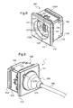
- This plug-in mechanism 100 forms with this electrical plug 200 a connection assembly 1 (see FIG. figure 3 ) which is here more particularly intended for the hospital environment.
- connection elements 220 of the electrical plug 200 are partly housed in an envelope 210 of insulating material, and are accessible through the front face 211 of the envelope 210.
- connection elements 120 of the socket mechanism 100 are also housed in an envelope 110 of insulating material, and are accessible through the front face 111 of the envelope 110.
- the casing 110 of the socket mechanism 100 fully houses, near its front face 111, a magnetic element 130, and the casing 210 of the electrical plug 200 fully houses , near its front face 211, a magnetizable element 230 non-magnetic.
- These magnetic and magnetizable elements 130, 230 are designed to hold the electrical plug 200 in position plugged into the socket mechanism 100, so as to close the electrical circuit between the call bulb and the hospital electrical network.
- a magnetic element 130 (rather than a mechanical detent element which may deteriorate) in the socket mechanism 100 ensures that the tensile force required to disengage the electrical plug 200 out of the socket mechanism 100 does not change over time.
- the socket mechanism 100 and the electrical plug 200 are preferably designed so that, in the plugged-in position, the magnetic element 130 induces on the magnetizable element 230 a pulling force of between 20 and 40 Newton.
- This attraction force is also low enough so that, in an emergency (typically on rising or lowering of the patient's bed), the electrical plug 200 can disconnect quickly without deteriorating or damaging the setting mechanism current 100.
- the socket mechanism 100 and the electrical plug 200 are preferably designed so that, in the plugged position, the magnetic and magnetizable elements 130, 230 are spaced apart by a distance, called the air gap, of between 1 and 3 millimeters. This gap is here equal to 2 millimeters.
- the bottom 114 of the casing 110 has a flat and square rear wall 114A, bordered at the front by a peripheral rib 114B.
- the sleeve 113 is of square parallelepipedal shape, with four side walls 113B lined at the front, on the side of their inner faces, by a front edge 113A which delimits a wide circular opening 113G.
- the side walls 113B bear on their external faces, near the front edge 113A, a sidewalk 113C device which is here partially interrupted by indentations.
- the hubcap 112 comprises meanwhile a front plate 112A flat and square, bordered at the rear by a falling edge 112B.
- the front plate 112A recesses a well 112C crossing the home of the electrical plug 200, which is delimited by a cylindrical side wall.
- the falling edge 112B is adapted to be applied by its rear edge on the sidewalk 113C of the sleeve 113.
- the sleeve 113 For its mounting on the bottom 114 of the casing 110, the sleeve 113 comprises, on two opposite side walls 113B, four windows 113D.
- the bottom 114 carries in correspondence four latching lugs 114D which rise from its peripheral rib 114B, orthogonal to its rear wall 114A, and which bear claws adapted to catch on the windows 113D of the sleeve 113.
- the sleeve 113 comprises, at the front of the flange 113C, on two opposite side walls 113B, four grooves 113E in which claws 112E can be hooked up projecting from the inner face of the falling edge. 112B of the hubcap 112.
- the sleeve 113 For the mounting of the casing 110 of the socket mechanism 100 in the electrical box attached to the wall of the hospital chamber, the sleeve 113 comprises fixing means on an equipment support (not shown) which is itself adapted to be fixed on the electrical box.
- These fastening means comprise two latching tabs 113F which are cut in two opposite side walls 113B of the sleeve 113, at the rear of the flange 113C, and which bear claws adapted to hook onto the rear face of the support of FIG. apparatus when the sidewalk 113C of the sleeve 113 bears against the front face of this equipment support.
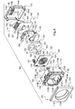
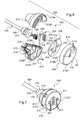
- the envelope 110 of the socket mechanism 100 When assembled, the envelope 110 of the socket mechanism 100 internally houses, from the front to the back, a printed circuit 125, an anti-short circuit element 140, the magnetic element 130, a support means 150 of the magnetic element 130, and a connection element 160 of the printed circuit 125. These different elements are superimposed and are held in position between the rear wall 114A of the bottom 114 and the front flange 113A of the sleeve 113.
- the support 126 has a thickness equal to 0.8 millimeters and a width, equal to the play, to the internal width of the sleeve 113. It is thus adapted to be pressed against the rear face of the front flange 113A of the sleeve 113. In this position, it closes the circular opening 113G delimited by the front flange 113A of the sleeve 113 and thus forms the bottom of the well 112C insertion of the electrical plug 200.
- the support 126 of the printed circuit 125 then has on the front face a white varnish, which is visible and which gives the whole a neat and clean appearance.
- the support 126 on its front face, carries four tracks 121, 122, 123, 124 extending in concentric circles in the center of the support.
- the diameter of the track of larger diameter is smaller than that of the circular opening 113G delimited by the front flange 113A of the sleeve 113. In this way, these four tracks 121, 122, 123, 124 are accessible at the bottom of the well 112C insertion of the electric plug 200.
- connection element 160 comprises a printed circuit, called the rear printed circuit 161, and a terminal block 162 which has four connection terminals (not visible in the figures). and which is attached to the rear of the rear printed circuit board 161.
- the rear printed circuit 161 comprises a support of dimensions identical to those of the support of the printed circuit 125, and copper tracks which extend on the rear face of this support.
- the terminal block 162 here comprises a base 167 made of insulating plastic material which internally houses the four connection terminals.
- This base 167 has a generally parallelepiped shape and is elongated along an axis parallel to the plane of the support of the rear printed circuit 161 to accommodate the four connection terminals in side-by-side position.
- This base 167 has on the rear face four first parallel holes 164 to access the four connection terminals, which allow to engage the stripped ends of four son of the hospital electrical network in the four connection terminals.
- Four rectangular windows 114C are provided in correspondence in the rear wall 114A of the bottom 114 of the casing 110, to allow access to the first four parallel holes 164.
- the base 167 of the terminal block 162 also has on the side face four second parallel holes 163 for accessing tapped bores equipping the four connection terminals. These tapped bores accommodate four fastening screws (not shown) to block the stripped ends of the four son in the four connection terminals to connect them. As shown in figure 2 , the envelope 110 then has an access opening 110H to these four parallel second holes 163, to allow the tip of a screwdriver to access the heads of these fixing screws.
- this access opening 110H is defined between two notches 113H, 114H, one of which is recessed in the rear edge of one of the side walls 113B of the sleeve 113 of the envelope 110 and the other of which is provided hollow in the front edge of the peripheral rib 114B of the bottom 114 of the casing 110.
- the base 167 of the terminal block 162 has on the front face four third parallel holes (not visible in the figures), which allow four metal pins 165 fitted to the four connection terminals to project at the front of the base 167.
- These four pins metal 165 are engaged in four vias provided in correspondence in the support of the rear printed circuit 161. They then allow not only to fix the terminal block 162 to the rear printed circuit 161, but also to connect the four connection terminals to the tracks of this rear printed circuit 161.
- connection terminals are thus connected to the four tracks 121, 122, 123, 124 provided on the front face of the support of the printed circuit 125.
- the anti-short circuit element 140 comprises a disc-shaped base 142, and a pin 141 which protrudes from the center of the front face of the base 142.
- the base 142 has a diameter much smaller than the width of the printed circuit 125. It is thus adapted to be applied against the rear face of the support 126 of the printed circuit 125 so that the pin 141 engages through an opening 128 provided in correspondence with the center of the support 126 of the printed circuit 125.
- the pin 141 has for this purpose a diameter smaller than that of the track 121 of smaller diameter and equal, with the game, to that of the opening 128. It also has a height strictly greater than the thickness of the support 126 of the printed circuit 125.
- the anti-short circuit element 140 is made in one piece of insulating plastic material.
- the pin 141 will prevent this object from being applied to this printed circuit 125 and to enter simultaneously in contact with several tracks 121, 122, 123, 124 of the printed circuit 125.
- the anti-short circuit element 140 can thus avoid the occurrence of a short circuit.
- the magnetic element 130 is placed between the connection element 160 and the anti-short circuit element 140.
- the magnet 131 has a cylindrical shape of revolution about an axis A1 orthogonal to the plane of the support 126 of the printed circuit 125. It has a diameter of 32 millimeters and a height of 7 millimeters. It is thus accommodable in a casing 110 of socket mechanism 100 of conventional size. It presents here a central through hole 133 of axis A1, of diameter slightly lower than that of the base 142 of the anti-short circuit element 140.
- the magnetizable element 230 of the electrical plug 200 is automatically centered in the axis A1 of the magnet 131 when brought close to it.
- the metal cage 132 has a shape and dimensions homologous to those of the magnet 131. It is attached to the magnet 131 in the extension thereof, and thus makes it possible to orient the magnetic flux coming from the magnet 131. 131 magnet in a single half-sphere facing forward, so as to optimize the attractive force generated by the magnet 131 and to protect the back of the socket 100 of the magnetic field from the magnet 131.
- the support means 150 of the magnetic element 130 is arranged to hold the latter in a fixed position in the envelope 110.
- FIG. 5 it comprises for this purpose a cradle 151 for receiving the magnetic element 130, and fixing means 152, 157 of this cradle 151 on the printed circuits 125, 161.
- the cradle 151 has a flat bottom 153 of generally rectangular shape, with two opposite edges rectilinear and parallel, and two other rounded opposite edges, circumscribed to the same circle of diameter equal to that of the magnetic element 130. It also comprises two flanges 154 which rise vis-à-vis from these two rounded edges, on a height approximately equal to that of the magnetic element 130, to delimit between them a housing for receiving this magnetic element 130.
- each rim 156 has a lug 157 which projects from its projection. front face to engage in a hole 129 provided in correspondence in the support 127 of the printed circuit 125. These pins 157 and allow to properly center the magnetic element 130 in the axis of the support 127 of the printed circuit 125.
- the cradle 151 also rests on the support of the rear printed circuit 161 by two rectilinear and parallel ribs 155 which project from the rear face of its flat bottom 153.
- latching means here comprising two latching lugs 152.
- latching means here comprising two latching lugs 152.
- these two latching tabs 152 extend in length from the rear face of the flat bottom 153 of the cradle 151, orthogonally thereto, and carry at their free ends two claws facing away from each other. the other.
- the support of the rear printed circuit 161 comprises in correspondence two circular openings 166 through which the detent tabs 152 can engage so that their claws cling to the rear face of this support.
- the electrical plug 200 is for its part represented on the figures 1 and 6 .
- Its envelope 210 generally has a right conical shape of A2 axis of revolution, whose vertex is truncated.
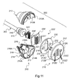
- It is made of three distinct parts, each resulting from molding of an insulating plastic material. It more particularly comprises a front cover 212, which forms the base of the cone, and a rear body 216 consisting of two parts 213, 214 identical, which forms the side wall of the cone.
- the front cover 212 has a front wall 212A disk-shaped axis of revolution A2, which is bordered on the rear side by a falling edge 212B cylindrical about the axis of revolution A2.
- the front wall 212A has a small thickness, here equal to 1.2 millimeters, arranged so that the air gap provided between the magnetic elements 130 and magnetizable 230 has a reduced value.
- This front wall 212A has a central orifice 212C of equal diameter, clearance, to that of the pin 141 of the anti-short circuit element 140 of the socket mechanism 100.
- the electrical plug 200 can be attached to the bottom of the well 112C of the socket mechanism 100, so that the front face 211 of its casing 210 is uniformly applied against the front face of the circuit board 125 of the socket mechanism 100.
- the falling edge 212B of the front cover 212 for its part, has an outside diameter equal, with play, to the diameter of the well 112C of the socket mechanism 100.
- the electrical plug 200 is adapted to be centered automatically, by form cooperation, in well 112C.
- the two parts 213, 214 of the rear body 216 of the casing 210 allow to connect continuously and aesthetically the front cover 212 to the side face of the electric cable 300.
- the truncated apex of the cone has for this purpose a square opening 215 for the passage of the electric cable 300.
- the latter is equipped, near its free end, with a generally conical seal 310 which, as shown in FIG. figure 1 , is designed to aesthetically extend the conical shape of the envelope 210.
- this joint 310 has at mid-height a narrowing section 315 of square shape, on which can close the square opening 215 of the casing 210.
- the base of the cone formed by the two parts 213, 214 of the rear body 216 of the casing 210 is further closed by a partition 214B, 214C which defines an oblong central opening 217.
- the two parts 213, 214 of the rear body 216 of the casing 210 are adapted to fit one on the other and to lock in this position by means of latching means 218, 219.
- connection elements 120 ', 220' which are accessible on the front faces 111, 211 of the envelopes 110, 210 of the electrical plug 200 and socket 100 are indeed not arranged on circles.
Landscapes
- Details Of Connecting Devices For Male And Female Coupling (AREA)
Applications Claiming Priority (1)
| Application Number | Priority Date | Filing Date | Title |
|---|---|---|---|
| FR1004680A FR2968467B1 (fr) | 2010-12-01 | 2010-12-01 | Prise de courant et fiche electrique equipees de moyens d'attraction magnetique |
Publications (2)
| Publication Number | Publication Date |
|---|---|
| EP2461429A1 true EP2461429A1 (de) | 2012-06-06 |
| EP2461429B1 EP2461429B1 (de) | 2014-03-19 |
Family
ID=44064625
Family Applications (1)
| Application Number | Title | Priority Date | Filing Date |
|---|---|---|---|
| EP11290506.2A Active EP2461429B1 (de) | 2010-12-01 | 2011-11-02 | Steckdose und elektrischer Stecker, die mit Mitteln zur magnetischen Anziehung ausgestattet sind |
Country Status (2)
| Country | Link |
|---|---|
| EP (1) | EP2461429B1 (de) |
| FR (1) | FR2968467B1 (de) |
Cited By (13)
| Publication number | Priority date | Publication date | Assignee | Title |
|---|---|---|---|---|
| ITUB20153204A1 (it) * | 2015-08-24 | 2017-02-24 | Scudomatica Srl | Sistema di connessione tra Apparati Mobili Elettrici ed Elettronici a Strutture Fisse di Cablaggio |
| WO2017072620A1 (fr) * | 2015-10-27 | 2017-05-04 | Fischer Connectors Holding S.A. | Connecteur multipolaire |
| EP3503309A1 (de) * | 2017-12-20 | 2019-06-26 | Insta GmbH | Elektrisches/elektronisches installationsgerät |
| EP3503310A1 (de) * | 2017-12-20 | 2019-06-26 | Insta GmbH | Elektrisches/elektronisches installationsgerät |
| EP3527886A1 (de) * | 2018-02-15 | 2019-08-21 | Insta GmbH | Elektrische leuchte |
| EP3527887A1 (de) * | 2018-02-15 | 2019-08-21 | Insta GmbH | Elektrische leuchte |
| EP3527885A1 (de) * | 2018-02-15 | 2019-08-21 | Insta GmbH | Elektrische leuchte |
| CN112186440A (zh) * | 2020-09-27 | 2021-01-05 | 广州众盈达贸易有限公司 | 一种家居饰品用防误拔插头及插座 |
| US11050187B2 (en) | 2016-06-13 | 2021-06-29 | Gulplug | Electrical connection system |
| US11070000B2 (en) | 2019-11-22 | 2021-07-20 | International Business Machines Corporation | Magnetic power connection |
| AT523582A3 (de) * | 2020-03-06 | 2021-12-15 | H4X Eu | Befestigungsvorrichtung für eine flexible schlauchförmige Leuchteinrichtung, sowie Anordnung |
| US11374351B2 (en) | 2018-04-06 | 2022-06-28 | Fischer Connectors Holding S.A. | Multipolar connector |
| US11616324B2 (en) | 2018-04-06 | 2023-03-28 | Conextivity Group Sa | Multipolar connector |
Families Citing this family (1)
| Publication number | Priority date | Publication date | Assignee | Title |
|---|---|---|---|---|
| FR3120275B1 (fr) | 2021-03-01 | 2025-03-14 | Gulplug | Dispositif adaptable sur un véhicule électrique pour sa recharge |
Citations (6)
| Publication number | Priority date | Publication date | Assignee | Title |
|---|---|---|---|---|
| US3521216A (en) | 1968-06-19 | 1970-07-21 | Manuel Jerair Tolegian | Magnetic plug and socket assembly |
| DE19512335C1 (de) * | 1995-04-01 | 1996-08-29 | Fritsch Klaus Dieter | Elektromechanische Verbindungsvorrichtung |
| DE10149575A1 (de) * | 2001-10-08 | 2003-05-22 | Siegfried Baltzer | Permanentmagnetische Vielfachsteckdose mit Kabelsteckern |
| DE202004020179U1 (de) * | 2004-12-30 | 2005-03-03 | GS-Elektromedizinische Geräte, G. Stemple GmbH | Vorrichtung zur Herstellung einer elektrischen Verbindung zwischen einer Stromquelle und einem in einem Gehäuse angeordneten elektrischen Verbraucher |
| US20070072443A1 (en) * | 2005-09-26 | 2007-03-29 | Apple Computer, Inc. | Magnetic connector for electronic device |
| EP1921893A2 (de) | 2006-11-08 | 2008-05-14 | Siemens Audiologische Technik GmbH | Hörgerät und dazugehöriges Ladegerät |
Family Cites Families (3)
| Publication number | Priority date | Publication date | Assignee | Title |
|---|---|---|---|---|
| FR2665305B1 (fr) * | 1990-07-24 | 1994-04-08 | Applications Gles Elect Meca | Connecteur comportant une embase anti-vandale et une fiche cooperante. |
| CH681121A5 (en) * | 1990-10-10 | 1993-01-15 | Erwin Meister | Low current electrical connector e.g. for recording-playback system - has base with circuit plate and contacts retained against plug section by field generated by permanent |
| DE10333403A1 (de) * | 2003-07-14 | 2004-09-23 | Albert Ackermann Gmbh & Co. Kg | Steckverbindersystem |
-
2010
- 2010-12-01 FR FR1004680A patent/FR2968467B1/fr not_active Expired - Fee Related
-
2011
- 2011-11-02 EP EP11290506.2A patent/EP2461429B1/de active Active
Patent Citations (6)
| Publication number | Priority date | Publication date | Assignee | Title |
|---|---|---|---|---|
| US3521216A (en) | 1968-06-19 | 1970-07-21 | Manuel Jerair Tolegian | Magnetic plug and socket assembly |
| DE19512335C1 (de) * | 1995-04-01 | 1996-08-29 | Fritsch Klaus Dieter | Elektromechanische Verbindungsvorrichtung |
| DE10149575A1 (de) * | 2001-10-08 | 2003-05-22 | Siegfried Baltzer | Permanentmagnetische Vielfachsteckdose mit Kabelsteckern |
| DE202004020179U1 (de) * | 2004-12-30 | 2005-03-03 | GS-Elektromedizinische Geräte, G. Stemple GmbH | Vorrichtung zur Herstellung einer elektrischen Verbindung zwischen einer Stromquelle und einem in einem Gehäuse angeordneten elektrischen Verbraucher |
| US20070072443A1 (en) * | 2005-09-26 | 2007-03-29 | Apple Computer, Inc. | Magnetic connector for electronic device |
| EP1921893A2 (de) | 2006-11-08 | 2008-05-14 | Siemens Audiologische Technik GmbH | Hörgerät und dazugehöriges Ladegerät |
Cited By (18)
| Publication number | Priority date | Publication date | Assignee | Title |
|---|---|---|---|---|
| ITUB20153204A1 (it) * | 2015-08-24 | 2017-02-24 | Scudomatica Srl | Sistema di connessione tra Apparati Mobili Elettrici ed Elettronici a Strutture Fisse di Cablaggio |
| WO2017072620A1 (fr) * | 2015-10-27 | 2017-05-04 | Fischer Connectors Holding S.A. | Connecteur multipolaire |
| CN108352665A (zh) * | 2015-10-27 | 2018-07-31 | 费希尔联接器股份有限公司 | 多极连接器 |
| JP2018532242A (ja) * | 2015-10-27 | 2018-11-01 | フィッシャー コネクターズ ホールディング ソシエテ アノニム | 多極コネクタ |
| US10574006B2 (en) | 2015-10-27 | 2020-02-25 | Fischer Connectors Holding Sa | Multipolar connector with circular contacts |
| US11050187B2 (en) | 2016-06-13 | 2021-06-29 | Gulplug | Electrical connection system |
| EP3503309A1 (de) * | 2017-12-20 | 2019-06-26 | Insta GmbH | Elektrisches/elektronisches installationsgerät |
| EP3503310A1 (de) * | 2017-12-20 | 2019-06-26 | Insta GmbH | Elektrisches/elektronisches installationsgerät |
| EP3527885A1 (de) * | 2018-02-15 | 2019-08-21 | Insta GmbH | Elektrische leuchte |
| EP3527887A1 (de) * | 2018-02-15 | 2019-08-21 | Insta GmbH | Elektrische leuchte |
| EP3527886A1 (de) * | 2018-02-15 | 2019-08-21 | Insta GmbH | Elektrische leuchte |
| US11374351B2 (en) | 2018-04-06 | 2022-06-28 | Fischer Connectors Holding S.A. | Multipolar connector |
| US11616324B2 (en) | 2018-04-06 | 2023-03-28 | Conextivity Group Sa | Multipolar connector |
| US11616320B2 (en) | 2018-04-06 | 2023-03-28 | Conextivity Group Sa | Multipolar connector |
| US11070000B2 (en) | 2019-11-22 | 2021-07-20 | International Business Machines Corporation | Magnetic power connection |
| AT523582A3 (de) * | 2020-03-06 | 2021-12-15 | H4X Eu | Befestigungsvorrichtung für eine flexible schlauchförmige Leuchteinrichtung, sowie Anordnung |
| AT523582B1 (de) * | 2020-03-06 | 2022-07-15 | H4X Eu | Befestigungsvorrichtung für eine flexible schlauchförmige Leuchteinrichtung, sowie Anordnung |
| CN112186440A (zh) * | 2020-09-27 | 2021-01-05 | 广州众盈达贸易有限公司 | 一种家居饰品用防误拔插头及插座 |
Also Published As
| Publication number | Publication date |
|---|---|
| FR2968467B1 (fr) | 2013-04-12 |
| FR2968467A1 (fr) | 2012-06-08 |
| EP2461429B1 (de) | 2014-03-19 |
Similar Documents
| Publication | Publication Date | Title |
|---|---|---|
| EP2461429B1 (de) | Steckdose und elektrischer Stecker, die mit Mitteln zur magnetischen Anziehung ausgestattet sind | |
| EP3231042B1 (de) | Stromsteckdosenvorrichtung mit mindestens einem verriegelungs- und entriegelungselement | |
| US7238028B2 (en) | Reorientable electrical receptacle | |
| EP0598811B2 (de) | Geschlechtloser elektrischer verbinder | |
| US20050255718A1 (en) | Connector | |
| FR2930848A3 (fr) | Prise electrique multiple de securite | |
| FR3014603A1 (fr) | Connecteur electrique femelle, connecteur electrique male correspondant et ensemble de connexion comportant des connecteurs male et femelle | |
| EP1037332A1 (de) | Schwachstromstecker mit einem Adapter und Adapter für einen solchen Stecker | |
| FR3051079A1 (fr) | Dispositif de verrouillage pour connecteurs electriques et connecteurs electriques equipes du dispositif. | |
| EP2584657A1 (de) | Verwechslungssicherungssystem für Anschluss, und Montageverfahren dieses Systems auf einem Anschluss | |
| KR101217322B1 (ko) | 전원 접속기구 | |
| FR3007900A1 (fr) | Appareillage electrique etendu | |
| KR101207296B1 (ko) | 플러그의 분리가 용이한 콘센트 | |
| FR2837323A1 (fr) | Dispositif d'alimentation electrique | |
| EP0660461B1 (de) | Mehrfacher Sockel für Steckdose | |
| FR3104331A1 (fr) | Prise de courant | |
| FR2877502A1 (fr) | Element de bornier et connecteur sans vis. | |
| KR100609659B1 (ko) | 부착식 전원접속기구 | |
| EP1006636A2 (de) | Unterputzdose für ein elektrisches Gerät | |
| FR2703845A1 (fr) | Socle de prise de courant. | |
| EP2936635A1 (de) | Elektrisches ausrüstungsmodul | |
| FR3038461B1 (fr) | Systeme de verrouillage d'un socle d'emboitement d'une prise avec une prise, socle d'emboitement et prise associes | |
| WO1993011585A1 (fr) | Dispositif de connexion de securite pour branchement electrique | |
| FR2924535A1 (fr) | Appareillage electrique encastre a connexion rapide | |
| FR3071971A1 (fr) | Chargeur tres basse tension de type chargeur usb, adaptable sur une prise de courant |
Legal Events
| Date | Code | Title | Description |
|---|---|---|---|
| PUAI | Public reference made under article 153(3) epc to a published international application that has entered the european phase |
Free format text: ORIGINAL CODE: 0009012 |
|
| AK | Designated contracting states |
Kind code of ref document: A1 Designated state(s): AL AT BE BG CH CY CZ DE DK EE ES FI FR GB GR HR HU IE IS IT LI LT LU LV MC MK MT NL NO PL PT RO RS SE SI SK SM TR |
|
| AX | Request for extension of the european patent |
Extension state: BA ME |
|
| 17P | Request for examination filed |
Effective date: 20120913 |
|
| GRAP | Despatch of communication of intention to grant a patent |
Free format text: ORIGINAL CODE: EPIDOSNIGR1 |
|
| RIC1 | Information provided on ipc code assigned before grant |
Ipc: H01R 13/62 20060101AFI20131101BHEP Ipc: H01R 12/91 20110101ALN20131101BHEP Ipc: H01R 13/44 20060101ALN20131101BHEP Ipc: H01R 103/00 20060101ALN20131101BHEP Ipc: H01R 12/71 20110101ALI20131101BHEP Ipc: H01R 24/78 20110101ALN20131101BHEP |
|
| INTG | Intention to grant announced |
Effective date: 20131127 |
|
| GRAS | Grant fee paid |
Free format text: ORIGINAL CODE: EPIDOSNIGR3 |
|
| GRAA | (expected) grant |
Free format text: ORIGINAL CODE: 0009210 |
|
| AK | Designated contracting states |
Kind code of ref document: B1 Designated state(s): AL AT BE BG CH CY CZ DE DK EE ES FI FR GB GR HR HU IE IS IT LI LT LU LV MC MK MT NL NO PL PT RO RS SE SI SK SM TR |
|
| REG | Reference to a national code |
Ref country code: GB Ref legal event code: FG4D Free format text: NOT ENGLISH |
|
| REG | Reference to a national code |
Ref country code: CH Ref legal event code: EP |
|
| REG | Reference to a national code |
Ref country code: IE Ref legal event code: FG4D Free format text: LANGUAGE OF EP DOCUMENT: FRENCH |
|
| REG | Reference to a national code |
Ref country code: AT Ref legal event code: REF Ref document number: 658205 Country of ref document: AT Kind code of ref document: T Effective date: 20140415 |
|
| REG | Reference to a national code |
Ref country code: DE Ref legal event code: R096 Ref document number: 602011005491 Country of ref document: DE Effective date: 20140430 |
|
| PG25 | Lapsed in a contracting state [announced via postgrant information from national office to epo] |
Ref country code: LT Free format text: LAPSE BECAUSE OF FAILURE TO SUBMIT A TRANSLATION OF THE DESCRIPTION OR TO PAY THE FEE WITHIN THE PRESCRIBED TIME-LIMIT Effective date: 20140319 Ref country code: NO Free format text: LAPSE BECAUSE OF FAILURE TO SUBMIT A TRANSLATION OF THE DESCRIPTION OR TO PAY THE FEE WITHIN THE PRESCRIBED TIME-LIMIT Effective date: 20140619 |
|
| REG | Reference to a national code |
Ref country code: NL Ref legal event code: VDEP Effective date: 20140319 |
|
| REG | Reference to a national code |
Ref country code: LT Ref legal event code: MG4D |
|
| PG25 | Lapsed in a contracting state [announced via postgrant information from national office to epo] |
Ref country code: FI Free format text: LAPSE BECAUSE OF FAILURE TO SUBMIT A TRANSLATION OF THE DESCRIPTION OR TO PAY THE FEE WITHIN THE PRESCRIBED TIME-LIMIT Effective date: 20140319 Ref country code: SE Free format text: LAPSE BECAUSE OF FAILURE TO SUBMIT A TRANSLATION OF THE DESCRIPTION OR TO PAY THE FEE WITHIN THE PRESCRIBED TIME-LIMIT Effective date: 20140319 Ref country code: CY Free format text: LAPSE BECAUSE OF FAILURE TO SUBMIT A TRANSLATION OF THE DESCRIPTION OR TO PAY THE FEE WITHIN THE PRESCRIBED TIME-LIMIT Effective date: 20140319 |
|
| PG25 | Lapsed in a contracting state [announced via postgrant information from national office to epo] |
Ref country code: LV Free format text: LAPSE BECAUSE OF FAILURE TO SUBMIT A TRANSLATION OF THE DESCRIPTION OR TO PAY THE FEE WITHIN THE PRESCRIBED TIME-LIMIT Effective date: 20140319 Ref country code: RS Free format text: LAPSE BECAUSE OF FAILURE TO SUBMIT A TRANSLATION OF THE DESCRIPTION OR TO PAY THE FEE WITHIN THE PRESCRIBED TIME-LIMIT Effective date: 20140319 Ref country code: HR Free format text: LAPSE BECAUSE OF FAILURE TO SUBMIT A TRANSLATION OF THE DESCRIPTION OR TO PAY THE FEE WITHIN THE PRESCRIBED TIME-LIMIT Effective date: 20140319 |
|
| PG25 | Lapsed in a contracting state [announced via postgrant information from national office to epo] |
Ref country code: NL Free format text: LAPSE BECAUSE OF FAILURE TO SUBMIT A TRANSLATION OF THE DESCRIPTION OR TO PAY THE FEE WITHIN THE PRESCRIBED TIME-LIMIT Effective date: 20140319 Ref country code: EE Free format text: LAPSE BECAUSE OF FAILURE TO SUBMIT A TRANSLATION OF THE DESCRIPTION OR TO PAY THE FEE WITHIN THE PRESCRIBED TIME-LIMIT Effective date: 20140319 Ref country code: CZ Free format text: LAPSE BECAUSE OF FAILURE TO SUBMIT A TRANSLATION OF THE DESCRIPTION OR TO PAY THE FEE WITHIN THE PRESCRIBED TIME-LIMIT Effective date: 20140319 Ref country code: BG Free format text: LAPSE BECAUSE OF FAILURE TO SUBMIT A TRANSLATION OF THE DESCRIPTION OR TO PAY THE FEE WITHIN THE PRESCRIBED TIME-LIMIT Effective date: 20140619 Ref country code: RO Free format text: LAPSE BECAUSE OF FAILURE TO SUBMIT A TRANSLATION OF THE DESCRIPTION OR TO PAY THE FEE WITHIN THE PRESCRIBED TIME-LIMIT Effective date: 20140319 Ref country code: IS Free format text: LAPSE BECAUSE OF FAILURE TO SUBMIT A TRANSLATION OF THE DESCRIPTION OR TO PAY THE FEE WITHIN THE PRESCRIBED TIME-LIMIT Effective date: 20140719 |
|
| PG25 | Lapsed in a contracting state [announced via postgrant information from national office to epo] |
Ref country code: SK Free format text: LAPSE BECAUSE OF FAILURE TO SUBMIT A TRANSLATION OF THE DESCRIPTION OR TO PAY THE FEE WITHIN THE PRESCRIBED TIME-LIMIT Effective date: 20140319 Ref country code: ES Free format text: LAPSE BECAUSE OF FAILURE TO SUBMIT A TRANSLATION OF THE DESCRIPTION OR TO PAY THE FEE WITHIN THE PRESCRIBED TIME-LIMIT Effective date: 20140319 Ref country code: PL Free format text: LAPSE BECAUSE OF FAILURE TO SUBMIT A TRANSLATION OF THE DESCRIPTION OR TO PAY THE FEE WITHIN THE PRESCRIBED TIME-LIMIT Effective date: 20140319 |
|
| REG | Reference to a national code |
Ref country code: DE Ref legal event code: R097 Ref document number: 602011005491 Country of ref document: DE |
|
| PG25 | Lapsed in a contracting state [announced via postgrant information from national office to epo] |
Ref country code: PT Free format text: LAPSE BECAUSE OF FAILURE TO SUBMIT A TRANSLATION OF THE DESCRIPTION OR TO PAY THE FEE WITHIN THE PRESCRIBED TIME-LIMIT Effective date: 20140721 |
|
| PLBE | No opposition filed within time limit |
Free format text: ORIGINAL CODE: 0009261 |
|
| STAA | Information on the status of an ep patent application or granted ep patent |
Free format text: STATUS: NO OPPOSITION FILED WITHIN TIME LIMIT |
|
| PG25 | Lapsed in a contracting state [announced via postgrant information from national office to epo] |
Ref country code: DK Free format text: LAPSE BECAUSE OF FAILURE TO SUBMIT A TRANSLATION OF THE DESCRIPTION OR TO PAY THE FEE WITHIN THE PRESCRIBED TIME-LIMIT Effective date: 20140319 |
|
| 26N | No opposition filed |
Effective date: 20141222 |
|
| REG | Reference to a national code |
Ref country code: DE Ref legal event code: R097 Ref document number: 602011005491 Country of ref document: DE Effective date: 20141222 |
|
| PG25 | Lapsed in a contracting state [announced via postgrant information from national office to epo] |
Ref country code: MC Free format text: LAPSE BECAUSE OF FAILURE TO SUBMIT A TRANSLATION OF THE DESCRIPTION OR TO PAY THE FEE WITHIN THE PRESCRIBED TIME-LIMIT Effective date: 20140319 Ref country code: LU Free format text: LAPSE BECAUSE OF FAILURE TO SUBMIT A TRANSLATION OF THE DESCRIPTION OR TO PAY THE FEE WITHIN THE PRESCRIBED TIME-LIMIT Effective date: 20141102 |
|
| REG | Reference to a national code |
Ref country code: CH Ref legal event code: PL |
|
| PG25 | Lapsed in a contracting state [announced via postgrant information from national office to epo] |
Ref country code: CH Free format text: LAPSE BECAUSE OF NON-PAYMENT OF DUE FEES Effective date: 20141130 Ref country code: LI Free format text: LAPSE BECAUSE OF NON-PAYMENT OF DUE FEES Effective date: 20141130 Ref country code: SI Free format text: LAPSE BECAUSE OF FAILURE TO SUBMIT A TRANSLATION OF THE DESCRIPTION OR TO PAY THE FEE WITHIN THE PRESCRIBED TIME-LIMIT Effective date: 20140319 |
|
| REG | Reference to a national code |
Ref country code: IE Ref legal event code: MM4A |
|
| REG | Reference to a national code |
Ref country code: FR Ref legal event code: PLFP Year of fee payment: 5 |
|
| PG25 | Lapsed in a contracting state [announced via postgrant information from national office to epo] |
Ref country code: IE Free format text: LAPSE BECAUSE OF NON-PAYMENT OF DUE FEES Effective date: 20141102 |
|
| PG25 | Lapsed in a contracting state [announced via postgrant information from national office to epo] |
Ref country code: SM Free format text: LAPSE BECAUSE OF FAILURE TO SUBMIT A TRANSLATION OF THE DESCRIPTION OR TO PAY THE FEE WITHIN THE PRESCRIBED TIME-LIMIT Effective date: 20140319 |
|
| PG25 | Lapsed in a contracting state [announced via postgrant information from national office to epo] |
Ref country code: GR Free format text: LAPSE BECAUSE OF FAILURE TO SUBMIT A TRANSLATION OF THE DESCRIPTION OR TO PAY THE FEE WITHIN THE PRESCRIBED TIME-LIMIT Effective date: 20140620 |
|
| PG25 | Lapsed in a contracting state [announced via postgrant information from national office to epo] |
Ref country code: HU Free format text: LAPSE BECAUSE OF FAILURE TO SUBMIT A TRANSLATION OF THE DESCRIPTION OR TO PAY THE FEE WITHIN THE PRESCRIBED TIME-LIMIT; INVALID AB INITIO Effective date: 20111102 Ref country code: TR Free format text: LAPSE BECAUSE OF FAILURE TO SUBMIT A TRANSLATION OF THE DESCRIPTION OR TO PAY THE FEE WITHIN THE PRESCRIBED TIME-LIMIT Effective date: 20140319 Ref country code: MT Free format text: LAPSE BECAUSE OF FAILURE TO SUBMIT A TRANSLATION OF THE DESCRIPTION OR TO PAY THE FEE WITHIN THE PRESCRIBED TIME-LIMIT Effective date: 20140319 |
|
| REG | Reference to a national code |
Ref country code: FR Ref legal event code: PLFP Year of fee payment: 6 |
|
| REG | Reference to a national code |
Ref country code: FR Ref legal event code: PLFP Year of fee payment: 7 |
|
| PG25 | Lapsed in a contracting state [announced via postgrant information from national office to epo] |
Ref country code: MK Free format text: LAPSE BECAUSE OF FAILURE TO SUBMIT A TRANSLATION OF THE DESCRIPTION OR TO PAY THE FEE WITHIN THE PRESCRIBED TIME-LIMIT Effective date: 20140319 |
|
| PG25 | Lapsed in a contracting state [announced via postgrant information from national office to epo] |
Ref country code: AL Free format text: LAPSE BECAUSE OF FAILURE TO SUBMIT A TRANSLATION OF THE DESCRIPTION OR TO PAY THE FEE WITHIN THE PRESCRIBED TIME-LIMIT Effective date: 20140319 |
|
| P01 | Opt-out of the competence of the unified patent court (upc) registered |
Effective date: 20230519 |
|
| PGFP | Annual fee paid to national office [announced via postgrant information from national office to epo] |
Ref country code: DE Payment date: 20251022 Year of fee payment: 15 |
|
| PGFP | Annual fee paid to national office [announced via postgrant information from national office to epo] |
Ref country code: GB Payment date: 20251022 Year of fee payment: 15 |
|
| PGFP | Annual fee paid to national office [announced via postgrant information from national office to epo] |
Ref country code: AT Payment date: 20251024 Year of fee payment: 15 |
|
| PGFP | Annual fee paid to national office [announced via postgrant information from national office to epo] |
Ref country code: IT Payment date: 20251022 Year of fee payment: 15 |
|
| PGFP | Annual fee paid to national office [announced via postgrant information from national office to epo] |
Ref country code: FR Payment date: 20251022 Year of fee payment: 15 |
|
| PGFP | Annual fee paid to national office [announced via postgrant information from national office to epo] |
Ref country code: BE Payment date: 20251022 Year of fee payment: 15 |