EP2461987B1 - Procédé pour la fabrication de carreaux de mosaïque prétraités avec du ciment et carreau prétraité avec du ciment - Google Patents
Procédé pour la fabrication de carreaux de mosaïque prétraités avec du ciment et carreau prétraité avec du ciment Download PDFInfo
- Publication number
- EP2461987B1 EP2461987B1 EP10752193.2A EP10752193A EP2461987B1 EP 2461987 B1 EP2461987 B1 EP 2461987B1 EP 10752193 A EP10752193 A EP 10752193A EP 2461987 B1 EP2461987 B1 EP 2461987B1
- Authority
- EP
- European Patent Office
- Prior art keywords
- tiles
- sheet element
- grooves
- panel
- sheet
- Prior art date
- Legal status (The legal status is an assumption and is not a legal conclusion. Google has not performed a legal analysis and makes no representation as to the accuracy of the status listed.)
- Not-in-force
Links
- 238000000034 method Methods 0.000 title claims description 54
- 238000004519 manufacturing process Methods 0.000 title claims description 13
- 239000000463 material Substances 0.000 claims description 47
- 239000011324 bead Substances 0.000 claims description 18
- 230000002093 peripheral effect Effects 0.000 claims description 15
- 238000003856 thermoforming Methods 0.000 claims description 14
- 239000012790 adhesive layer Substances 0.000 claims description 10
- 239000011347 resin Substances 0.000 claims description 9
- 229920005989 resin Polymers 0.000 claims description 9
- 239000010410 layer Substances 0.000 claims description 7
- 239000000853 adhesive Substances 0.000 claims description 5
- 230000001070 adhesive effect Effects 0.000 claims description 5
- 238000001816 cooling Methods 0.000 claims description 5
- 238000009826 distribution Methods 0.000 claims description 5
- 229920001169 thermoplastic Polymers 0.000 claims description 5
- 239000004416 thermosoftening plastic Substances 0.000 claims description 5
- 239000006260 foam Substances 0.000 claims description 4
- 238000010438 heat treatment Methods 0.000 claims description 4
- 235000011837 pasties Nutrition 0.000 claims description 2
- 229920000098 polyolefin Polymers 0.000 claims description 2
- 238000005507 spraying Methods 0.000 claims description 2
- 230000001737 promoting effect Effects 0.000 claims 1
- 238000003825 pressing Methods 0.000 description 5
- 230000015572 biosynthetic process Effects 0.000 description 3
- 230000000007 visual effect Effects 0.000 description 3
- 239000002313 adhesive film Substances 0.000 description 2
- 230000009977 dual effect Effects 0.000 description 2
- 239000003292 glue Substances 0.000 description 2
- 239000013067 intermediate product Substances 0.000 description 2
- 230000001788 irregular Effects 0.000 description 2
- 239000000047 product Substances 0.000 description 2
- 239000004634 thermosetting polymer Substances 0.000 description 2
- 239000004698 Polyethylene Substances 0.000 description 1
- 239000000654 additive Substances 0.000 description 1
- 238000010420 art technique Methods 0.000 description 1
- 239000000919 ceramic Substances 0.000 description 1
- 238000004140 cleaning Methods 0.000 description 1
- 239000003086 colorant Substances 0.000 description 1
- 230000001419 dependent effect Effects 0.000 description 1
- 238000006073 displacement reaction Methods 0.000 description 1
- 230000000694 effects Effects 0.000 description 1
- 238000007730 finishing process Methods 0.000 description 1
- 239000011521 glass Substances 0.000 description 1
- 239000007788 liquid Substances 0.000 description 1
- 230000013011 mating Effects 0.000 description 1
- -1 polyethylene Polymers 0.000 description 1
- 229920000573 polyethylene Polymers 0.000 description 1
- 239000004575 stone Substances 0.000 description 1
- 229920001187 thermosetting polymer Polymers 0.000 description 1
- 229920006352 transparent thermoplastic Polymers 0.000 description 1
- 238000009827 uniform distribution Methods 0.000 description 1
- XLYOFNOQVPJJNP-UHFFFAOYSA-N water Substances O XLYOFNOQVPJJNP-UHFFFAOYSA-N 0.000 description 1
Images




Classifications
-
- B—PERFORMING OPERATIONS; TRANSPORTING
- B44—DECORATIVE ARTS
- B44C—PRODUCING DECORATIVE EFFECTS; MOSAICS; TARSIA WORK; PAPERHANGING
- B44C1/00—Processes, not specifically provided for elsewhere, for producing decorative surface effects
- B44C1/28—Uniting ornamental elements on a support, e.g. mosaics
-
- B—PERFORMING OPERATIONS; TRANSPORTING
- B44—DECORATIVE ARTS
- B44C—PRODUCING DECORATIVE EFFECTS; MOSAICS; TARSIA WORK; PAPERHANGING
- B44C3/00—Processes, not specifically provided for elsewhere, for producing ornamental structures
- B44C3/12—Uniting ornamental elements to structures, e.g. mosaic plates
- B44C3/123—Mosaic constructs
-
- Y—GENERAL TAGGING OF NEW TECHNOLOGICAL DEVELOPMENTS; GENERAL TAGGING OF CROSS-SECTIONAL TECHNOLOGIES SPANNING OVER SEVERAL SECTIONS OF THE IPC; TECHNICAL SUBJECTS COVERED BY FORMER USPC CROSS-REFERENCE ART COLLECTIONS [XRACs] AND DIGESTS
- Y10—TECHNICAL SUBJECTS COVERED BY FORMER USPC
- Y10T—TECHNICAL SUBJECTS COVERED BY FORMER US CLASSIFICATION
- Y10T428/00—Stock material or miscellaneous articles
- Y10T428/24—Structurally defined web or sheet [e.g., overall dimension, etc.]
- Y10T428/24479—Structurally defined web or sheet [e.g., overall dimension, etc.] including variation in thickness
Definitions
- the present invention generally finds application in the field of decorative arts and particularly relates to a method of making pre-grouted mosaic panels.
- the invention further relates to a pre-grouted mosaic panel that can be obtained by the above method.
- the tiles are mutually offset in one or more predetermined directions to define a plurality of grooves.
- the grooves are filled with an appropriate resin, generally of thermoset type, having adequate flexibility to allow the panel to be also mounted to curved surfaces.
- a grid which has a plurality of seats whose shape mates the shape of the tiles, and separated by a dual series of ribs designed to hold the tiles in spaced relation to define the grooves.
- the filling resin is directly poured onto the ribs, e.g. by suitable nozzles, and then cured to obtain the finished panel.
- a further drawback is that, in order to provide grooves of equal widths, the tiles are required to be locked in their position.
- US3335048 and WO2005/092638 disclose methods for forming pre-grouted mosaic tile panels as described above, which include a further step in which a press is actuated to act upon the tiles.
- the press will both allow containment of the filling material with the most uniform distribution, and locking of the tiles in their mutual positions.
- WO2005/092638 provides a method of making pre-grouted panels in which a plurality of pneumatically operated pins are used, which press upon respective tiles to lock them in their preset position.
- WO2007/110751 discloses a method of making pre-grouted mosaic panel containing all the features mentioned in the preamble of the independent claim 1.
- the object of the present invention is to overcome the above drawbacks, by providing a method of making pre-grouted mosaic panels that is very simple and cost-effective.
- a particular object is to provide a method of making pre-grouted mosaic panels that affords joint thickness control and prevents the filling material from leaking out of the exposed surface of the tiles.
- a further object is to provide a method of making pre-grouted mosaic panels that allows stable positioning of tiles during the grouting process, in a considerably simple and cost-effective manner.
- Another object is to provide a pre-grouted mosaic tile panel that can be laid in a simpler and quicker manner.
- Yet another object of the invention is to provide a method of making pre-grouted mosaic panels whose joints have a non-flat profile, with an aesthetically pleasant appearance.
- Another object of the invention is to provide pre-jointed panels that provide a substantially seamless visual effect when they are laid side-by-side, in adjacent positions.
- the method of the invention affords simple and cost-effective control of joint size, and further prevents the filling material from leaking out of the grooves from the exposed surfaces of the tiles, and avoids the associated cleaning requirements.
- the first sheet element may be a thermoformable sheet, designed to fill the grooves to define a plurality of jointing beads and a support layer integral therewith.
- the panel will have a very stable structure, because the support layer will be stably held on the tiles, by being integral with the jointing beads.
- the panel with this configuration may be easily laid on a wall or support surface to be covered, because it already has a support layer, and will not require the latter to be provided at a later time.
- the method of the invention provides pre-grouted mosaic tile panels.
- pre-grouted is intended to designate a panel formed of mosaic tiles arranged according to any preset pattern and spaced along one or more predetermined directions to define a plurality of lines, commonly known as grooves.
- a filling material such as a resin or a polymeric foam, a cementitious material or any other material commonly used for jointing wall or floor tiles, not necessarily in mosaic arrangement, to hold the mosaic tiles joined together and form the panel.
- the pre-grouted panel may be directly laid over a surface, such as a wall or a floor, in a quick and fast manner, without requiring any particular skill by the operator.
- Fig. 1 shows, by way of example and without limitation, a panel 1 that can, but will not necessarily be formed by the method of the present invention, and has a substantially rectangular shape.
- the panel 1 is composed of a plurality of tiles 2 aligned along parallel longitudinal rows, transversely offset with substantially constant gaps to define identical rectilinear grooves 3 arranged in a dual series of orthogonal lines.
- the panel 1 of the figures has a substantially rectangular shape, it may have any shape, such as a square, polygonal, circular or irregular shape, without limitation to the size of the panel or the tiles 2, which will not be necessarily identical in shape and/or colors.
- the materials that can be used for the tiles 2 may include, by way of example and without limitation to the invention, glass, ceramics, cementitious materials, stone materials or possibly synthetic polymeric materials.
- the tiles 2 have substantially coplanar upper surfaces 4 which are designed to be exposed once laid, and lower surfaces 5, also coplanar, which are designed to be attached to the laying surface and possibly have grooves or irregularities for increasing the grip with the bedding material.
- each tile 2 is substantially flat and parallel and will be joined by corresponding sloping lateral surfaces 5.
- the grooves 3 are filled with a special grouting material, such as a thermoplastic or thermoset resin, which at least partially covers the lateral surfaces 6 to define a plurality of jointing beads 3' for connecting the tiles 2 together.
- a special grouting material such as a thermoplastic or thermoset resin
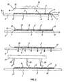
- Fig. 2 shows a succession of steps for making a pre-grouted panel 1 according to a first particular embodiment of the inventive method.
- the mosaic tiles 2 are laid over a substantially horizontal support base S in spaced positions, to define the grooves 3.
- the tiles 2 may be arranged with their lower surfaces 5 in contact with the support base S.
- the method may include an initial step in which a first mold 7 is provided, having a plurality of trays 8 designed for precisely housing and holding corresponding tiles 2.
- the trays 8 may have either an open or a closed bottom and their shape mates the shape of the tiles 2, with such a height has to leave an upper portion thereof free. Furthermore, the trays 8 are separated by a plurality of ribs 9 which are designed to keep the tiles 2 in spaced relation and define the joints 3.
- a step follows, in which a first polymeric sheet element 10 is laid on the top surfaces 4 of the mosaic tiles 2.
- the first sheet element 10 is thermoformed so that, once it has been thermoformed, it at least partially fills the grooves 3.
- the first sheet element 10 may consist of a transparent thermoplastic polymeric film, such as made of PET, PVC or the like.
- the film 10 is preferably as large as the finished panel 1 so that it can fully cover the upper surfaces 4 of all the tiles 2.
- the thermoforming step includes a step in which the polymeric film 10 is placed above the support base S, in a raised position relative to the tiles 2, and a later step in which such raised film 10 is heated to a predetermined temperature.
- the temperature will preferably range from 90° to 130°, but may change according to the material selected for the first sheet element 10.
- the polymeric film 10 may be supplied in individual sheets of substantially the same size as or a slightly larger size than the panel 1, to allow the formation of a substantially seamless peripheral edge 11.
- the polymeric film 10 may be unwound from a roll and cut to size both before and after thermoforming.
- the first mold 7 will have an outer peripheral frame 12 susceptible of supporting a peripheral portion 13 of the film 10 during thermoforming.
- the film 10 may be heated by one or more electrical resistors 14 located in the proximity of the free top surface 15 of the polymeric film 10, with the latter in a raised position. Nevertheless, other techniques may be equivalently used for heating the film 10, without departure from the scope of the invention.
- the polymeric film 10 may also have a bottom surface 16 with at least one layer of adhesive material for stable and removable bonding with the tiles 2.
- the thermoforming process may include an additional step in which pressure is applied on the first sheet element 10, once it has been heated and placed on the tiles 2, for partial filling of the grooves 3.
- pressure may be applied by suction of air from the grooves 3, which creates an at least partial vacuum and helps the film 10 to fit therein.
- the trays 8 of the first mold 7 preferably have an open bottom to allow air suction from the grooves 3.
- Optimal vacuum values may be about 1 atm negative pressure, although such values are by no means limited.
- Such intermediate product may be carried to a jointing station, where it will be turned upside-down and placed on a lying base L, that may be the same support surface S as used before, with the thermoformed polymeric film 10 in contact with such base L, for the groves 3 to be accessed from above.
- the panel 1 may undergo grouting, by filling a controlled amount of a filling material 17 in each grouted 3, to form the jointing beads 3' and, once the material has set, to obtain the pre-grouted panel 1 ready for application.
- the filling material 17 may be a pasty or semisolid state thermoplastic or thermoset resin, which is introduced in the grooves 3 to cover the convex portions of the film 10 and the lateral surfaces 6 of the tiles 2, thereby obtaining the pre-grouted panel 1.
- cementitious materials may be used, as well as any material that is commonly used for jointing panels, tiles and similar products.
- the particular convex shape of the film 10 in the grooves 3 will provide concave jointing beads 30, that will add a high aesthetic value to the finished panel 1.
- thermoformed film 10 will also prevent the resin 17 from leaking out of the grooves 3 during grouting and from even partially covering the exposed surfaces 4 of the tiles 2 and will thus avoid the associated final finishing process.
- the resin 17 may be distributed over part of the peripheral edge 13 of the thermoformed film 10, preferably on two contiguous sides thereof.
- the pre-grouted panel 1 will have two contiguous sides 11', 11" with jointing beads 3", 3"'.
- the pre-grouted panel 1 may be placed next to a pair of similar contiguous pre-grouted panels with its edges 11', 11" with the peripheral jointing beads 3", 3"' adjacent to the non pre-grouted edges of the other panels, for ensuring visual continuity of the assembly and further improving the aesthetic quality of the assembly.
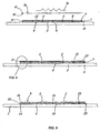
- peripheral jointing beads 3", 3"' may have a profile with a first concave section 18 and a second slanted section 19, with a slant substantially mating the one of the lateral surface 6 of the tiles 2, as more clearly shown in Fig. 3 .
- peripheral jointing beads 3", 3"' will cover the edge 11 of the peripheral tiles 2 of the contiguous panel 1', as shown in Fig. 4 .
- a frame may be placed at the periphery of the panel without the jointing beads 3', which frame has at least two contiguous sides with slanted edges that form an angle substantially similar to that of the lateral surfaces 6 of the tiles 2.
- the resin or other filling material 17 may be poured into the grooves 3 with any technique known in the art and may be preferably delivered by a plurality of nozzles 20 that are adapted to slide above corresponding grooves 3.
- the number of nozzles 20 may be smaller than the maximum number of parallel rows of grooves 3.
- the nozzles 20 may be mounted to a nozzle block 21 attached to an arm, not shown, that slides above the lying base L along at least a pair of orthogonal horizontal directions, for grouting a rectangular panel 1 without having to move it over the lying base L.
- the sliding arm may be mounted to a guiding carriage which is associated with a beam parallel to one of the two directions of motion, allowing displacement along such first direction.
- the beam may be in turn adapted to slide above the lying base L along special guides integral therewith or having a different support structure, and parallel to the second direction.
- the arm and/or the nozzle block 21 may be also connected to electronic means for continuous numerical control of the position of the nozzles 20 and their orientation relative to the lying base L to allow filling of grooves 3 of any shape, not necessarily rectilinear.
- the pre-grouted panel 1 so obtained may be simply and quickly laid on a wall or any other surface.
- thermoformed film 10 may be easily removed from the panel 1 either before or after the panel 1 is laid, without requiring later removal of any leaked jointing material.
- Fig. 5 shows a second succession of steps for making a pre-grouted panel 1 according to a further embodiment of the method, in which the tiles 2 are laid over the support base S with their lower surfaces 5 facing toward or in contact therewith, with or without the first mold 7.
- the tiles 2 are connected together by a second sheet element 22, more clearly shown in Fig. 6 , which is laid over the upper surfaces 4, and will not necessarily cover the whole of them.
- the first sheet element 10 also in this case a thermoformable polymeric film, may be placed on the second sheet element 22 and thermoformed thereon to define a second mold 23 having a bottom wall 24 defined by the thermoformed film 10 itself and a plurality of specially shaped seats 25 adapted to receive corresponding tiles 2.
- thermoforming process may be carried out as described above and may possibly include a step in which a predetermined pressure, possibly negative, is applied.
- the non grouted panel 1 composed of the tiles 2 joined together by the second sheet element 22 may be turned upside-down and inserted in the second mold 23 with the top surfaces 4 facing toward the bottom wall 24 of the second mold 23.
- the method may proceed with grouting by delivery of the resin or other filling material 17 as described above or according to alternative techniques.
- the second sheet element 22 may be removed either at the end of grouting or after laying of the panel 1, in any case preferably after substantial completion of the curing or setting of the grouting material 17.
- the second mold 23 may be used for grouting multiple similar panels or panels composed of a different number of tiles 2, as long as they have the same shape.
- the use of the first mold 7 will allow the second mold 23 to have peripheral edges 26 adapted to receive the filling material 17 and form a panel 1 with peripheral jointing beads 3", 3"'.
- the first embodiment of the method as described above and shown in Fig. 22 may also include the second sheet element 22 bonded to the tiles 2.
- thermoplastic film 10 with an adhesive layer on its bottom surface 16 will be directly bonded, after thermoforming, to the second sheet element 22, which is preferably non-thermoformable.
- Fig, 7 shows a third succession of steps for making a pre-grouted panel 1 according to a further embodiment of the inventive method.
- the first sheet element is a thermoformable sheet 27, e.g. a polymeric foam, having a greater thickness s than the above described film 10. which will be placed on the lower surfaces 5 of the tiles 2 and later thermoformed.
- thermoformable material will be preferably a thermoformable polymeric material and, by way of example and without limitation, may be selected from the group comprising polyolefin materials.
- it will be a polymeric, preferably polyolefin-, e.g. polyethylene-based foam, also with additives.
- thermoformable material will have a density ranging from 25Kg/m 3 to 400Kg/m 3 , preferably from 20Kg/m 3 to 100Kg/m 3 and more preferably substantially about 50Kg/m 3 .
- thermoplastic sheet 27 will be designed to define both the jointing beads 3', 3", 3'" of the panel 1 and the support layer 28 thereof, which will be integral with the beads 3', 3", 3"', as more clearly shown in Fig. 9 .
- the first sheet element 27 will have a thickness s preferably ranging from 1 mm to 15 mm, more preferably from 3 mm to 5 mm.
- the thickness s may be selected according to the material and/or the applications for which the panel 1 is designed, or according to the size of the tiles 2 or the desired size of the support layer 28 and/or the beads 3', 3", 3'".
- the first sheet element 27 may be supplied in individual sheets of substantially the same size as or a slightly larger size than the panel 1, to cover the whole lower surfaces 5 of all the tiles 2 and provide a substantially seamless peripheral edge 11 that at least partially surrounds the panel 1.
- the tiles 2 will be arranged over the support base S, with their upper surfaces 4 in contact with or facing toward the latter, and the lower surfaces 5 facing upwards.
- the tiles 2 will be held in spaced positions to define the grooves 3 and may be possibly joined together by the second sheet element 22, e.g. an adhesive film, which is applied to the top surfaces of the tiles 2 but will not necessarily cover the whole of them.
- the film 22 will be preferably designed to be removed after forming the panel 1 or laying it on the wall to be covered, and In any case preferably when the curing or setting of the material of the first sheet element 27 is substantially completed.
- the mold 27 described for the previous embodiment of the method may be also used.
- the film 10 will not be necessarily present.
- the method of the invention will thus include a step a) of provision of the tiles 2 and a step b) of arrangement thereof over the substantially horizontal lying plane ⁇ .
- thermoforming step After placing the first thermoformable sheet element 27 on the lower surface 5 of the tiles 2, with its top surface 29 facing toward the bottom surface of the tiles 2, the thermoforming step will be carried out thereon, so that it can penetrate the grooves 3 and at least partially fill them to define at least part of the jointing beads 3', 3", 3"'.
- top face of the first sheet element 27 is intended to designate the face 29 thereof which is designed to contact the lower surface 5 of the tiles 2, whatever the absolute position of the sheet element 27 in space. Accordingly, the term “bottom face” shall designate the face 30 of the same first sheet element 27 which is designed to face toward the laying face of the panel 1 and is not designed to contact the lower surface 5 of the tiles 2.
- thermoforming step may be carried out after the step in which the first sheet element 27 is positioned, or at least partially at the same time as such step.
- the first sheet element 27 will be placed above the support base S at a distance, particularly in a raised position, relative to the tiles 2.
- the thermoforming step will include a step in which such first sheet element 27 is heated to a predetermined temperature, preferably from 90° to 100°, and any way varying according to the material selected for the first sheet element 27.
- the first sheet element 27 may be heated by any known technique.
- one or more electrical resistors 14 may be used, which are located in the proximity of the free bottom surface 30 of the first sheet element 27, with the latter in a raised position or in contact with the tiles 2.
- the first sheet element 27 may be heated by passing it through a tunnel kiln, not shown. Nevertheless, other known techniques may be equivalently used for heating the first sheet element 27, without departure from the scope of the invention.
- thermoforming process may include an additional step in which pressure P is applied on the first sheet element 27, once it has been heated and placed on the tiles 2, for partial filling of the joints 3.
- the step of applying pressure on the first sheet element 27 may be carried out by direct pressing from above, e.g. using a press.
- the step of applying pressure P may include the application of a pressure P ranging from 20t/cm 2 e 30t/cm 2 for a time ranging from 5s to 100s and preferably from 10s to 90s, depending on the desired result.
- the step of applying pressure P may involve the creation of a negative pressure, e.g. by suction of air from below, as shown in the previous embodiment of the method.
- a negative pressure having a modulus as indicated above may be applied.
- the first sheet element 27 may be placed directly on the support base S with the tiles thereon and the pressure applied on the latter.
- This step of pressure application will allow the grooves 3 to be filled with the material of the first sheet element 27, and avoid the need for a further grouting step, by delivery of grouting material 17.
- Fig. 8 shows a fourth embodiment of the inventive method, which is similar to the one as shown in Fig. 7 , excepting that the tiles 2 are initially held in a substantially horizontal lying plane ⁇ , but in a raised position relative to the support base S and with the upper surfaces 4 facing upwards.
- the first sheet element 27 will be placed on the support base S with the bottom surface 30 facing toward and preferably in contact with it.
- the mold 27 may be provided also in this case.
- the pressure P may be applied in the manner as shown for the embodiment of Fig. 7 . If a press 31 is used, it can act both directly on the tiles 2 and on the first sheet element 27. A negative pressure may be also generated. Regardless of the particular embodiments of the method as described hereinbefore, the method of the invention may advantageously include a first step of distribution of at least one first adhesive layer on the top surface of the first sheet element 9, 27.
- the first adhesive step may be an adhesive film designed to be laid over the top surface 29 of the first sheet element 27.
- the second adhesive layer may be applied by spraying a glue material.
- the first and/or second adhesive layers are made of respective materials selected from the group of thermoformable glues.
- the step of applying pressure P will be carried out after the first and/or the second adhesive layer distribution steps.
- the method also includes a step in which the first heated sheet element 9, 27 is cooled, for example by cooling the mold, if there is any.
- cooling will be at least partially carried out during the pressure P application step. Cooling may occur either by air or liquid, e.g. water.
- the invention fulfils the intended objects and particularly meets the requirement of providing a method of making pre-grouted mosaic panels that affords joint thickness control and prevents the filling material from leaking out of the exposed surface of the tiles, thereby obtaining a finished product of high aesthetic value.
Landscapes
- Finishing Walls (AREA)
Claims (11)
- Procédé de fabrication de panneaux de mosaïque préjointoyés, dans lequel chaque panneau (1) est formé à partir d'une pluralité de carreaux de mosaïque (2) ayant chacun une surface supérieure (4) et une surface inférieure (5), comprenant les étapes suivantes :a) poser lesdits carreaux (2) sur une base de support (S) sensiblement horizontale dans des positions espacées mutuellement, afin de définir une pluralité de rainures (3) ;b) placer, après ladite étape de pose desdits carreaux (2), un premier élément en feuille polymérique thermoformable (10) sur les surfaces supérieure (4) et/ou inférieure (5) desdits carreaux de mosaïque (2) ;c) thermoformer dudit premier élément en feuille (10) placé sur lesdits carreaux, pour permettre audit premier élément en feuille thermoformé (10) de remplir au moins partiellement chacune desdites rainures (3)dans lequel le procédé comprend une étape initiale de fourniture d'un premier moule (7) ayant une pluralité de plateaux (8) conçus pour loger précisément et maintenir des carreaux correspondants (2) de ladite pluralité, lesdits plateaux (8) étant séparés par une pluralité de nervures (9) aptes à maintenir lesdits carreaux (2) selon une relation espacée, afin de définir lesdites rainures (3),
caractérisé en ce que lesdits carreaux (2) sont reliés entre eux par un second élément en feuille non-thermoformable (22) posé sur leur surface supérieure (4), ledit premier élément en feuille (10) étant placé sur ledit second élément en feuille (22) et thermoformé sur celui-ci afin de définir un second moule (23) ayant une paroi inférieure (24) définie par ledit premier élément en feuille thermoformé (10) et présentant une pluralité de sièges conformés (25) afin de précisément recevoir les carreaux correspondants (2), lesdits carreaux (2) étant insérés dans des sièges correspondants (25) dudit second moule (2) avec leur surface supérieure (4) respective orientée vers ladite paroi inférieure (24), - Procédé selon la revendication 1, caractérisé en ce que ladite étape de thermoformage comporte une étape de fourniture dudit premier élément en feuille (10) dans une position espacée par rapport auxdits carreaux (2) et une étape de chauffage à une température prédéterminée dudit premier élément en feuille espacé (10).
- Procédé selon la revendication 1 ou 2, caractérisé en ce que ladite étape de thermoformage comporte une étape d'application d'une pression sur ledit premier élément en feuille (10) chauffé et positionné sur lesdits carreaux (2) afin de favoriser le remplissage partiel desdits joints (3).
- Procédé selon la revendication 3, caractérisé en ce que ladite étape d'application de pression est réalisée par une aspiration d'air depuis lesdites rainures (3) pour que les parties dudit premier élément en feuille (10) dans lesdites rainures (3) soient convexes vers ladite base de support (S).
- Procédé selon l'une ou plusieurs de revendications précédentes, caractérisé en ce que ledit premier élément en feuille (10) est un film polymérique thermoplastique au moins aussi grand que le panneau fini (1), ledit film polymérique (10) ayant une surface supérieure libre (15) et une surface inférieure (16) ayant au moins une couche adhésive permettant de coller sur celle-ci lesdits carreaux (2) de manière stable et amovible.
- Procédé selon l'une quelconque des revendications 1 à 5, caractérisé en ce que ledit premier élément en feuille (10) est une feuille de matière thermoformable sélectionnée parmi le groupe constitué de matières polyoléfiniques et de mousses polymériques présentant une densité allant de 25 kg/m3 à 400 kg/m3, de préférence de 20 kg/m3 à 100 kg/m3 et plus préférentiellement sensiblement d'environ 50 kg/m3, ledit premier élément en feuille (10) présentant une épaisseur (s) allant de 1 mm à 15 mm, de préférence de 3 mm à 5 mm, et conçu pour remplir lesdites rainures (3) afin de définir une pluralité de cordons de jointoiement (7) et une couche de support (8) solidaire desdits cordons de jointoiement (7).
- Procédé selon la revendication 6, caractérisé en ce que ladite étape de chauffage de ladite feuille (10) est réalisée après avoir placé ladite feuille (10) sur ladite surface inférieure (5) desdits carreaux (2), avant ladite étape d'application de pression, une première étape (g) est effectuée pour répartir au moins une première couche adhésive composée d'une matière adhésive thermoformable sur la surface supérieure (15) dudit premier élément en feuille (10) et éventuellement une seconde étape (h) de répartition d'au moins une seconde couche adhésive composée d'une matière adhésive thermoformable sur la surface inférieure (5) desdits carreaux (2), ladite première étape et/ou ladite seconde étape (h) de répartition de ladite au moins une première et/ou seconde couche(s) adhésive(s) étant réalisée(s) en pulvérisant les matières adhésives respectives.
- Procédé selon l'une ou plusieurs des revendications précédentes, caractérisé en ce qu'il comprend une étape (i) de refroidissement d'au moins ledit premier élément en feuille chauffé (10), ladite étape de refroidissement (1) étant réalisée au moins partiellement en même temps que l'étape d'application de pression (f).
- Procédé selon la revendication 1, caractérisé en ce qu'il comprend une étape de retournement desdits carreaux (2) associés avec le premier (10) et/ou le second (22) élément en feuille afin de pouvoir accéder audites rainures (3) de l'extérieur, une étape suivante de jointoiement étant en outre prévue, qui est réalisée en répartissant une résine à l'état pâteux ou semi-solide dans lesdites rainures (3) pour former une pluralité de cordons de jointoiement (11) afin de recouvrir les parties dudit premier (10) ou second (22) élément en feuille dans lesdites rainures (3) et les surfaces latérales (6) desdits carreaux (2) afin de former un panneau préjointé (1).
- Procédé selon la revendication 9, caractérisé en ce que ledit premier moule (7) comporte un cadre périphérique (12) susceptible de supporter ledit premier élément en feuille (10) lors de ladite étape de thermoformage, pour que ledit premier élément en feuille thermoformé (10) présente un bord périphérique sensiblement ininterrompu (13).
- Procédé selon la revendication 9, caractérisé en ce que ladite résine est répartie sur au moins une partie dudit bord périphérique (13) dudit premier élément en feuille thermoformé (10), de préférence sur au moins deux côtés contigus de celui-ci.
Applications Claiming Priority (3)
| Application Number | Priority Date | Filing Date | Title |
|---|---|---|---|
| ITVI2009A000206A IT1395682B1 (it) | 2009-08-03 | 2009-08-03 | Metodo per la realizzazione di pannelli in mosaico prefugati e pannello in mosaico prefugato |
| IT000041A ITVI20100041A1 (it) | 2010-02-22 | 2010-02-22 | Metodo per la realizzazione di pannelli in mosaico prefugati e pannello in mosaico prefugato |
| PCT/IB2010/053458 WO2011015976A1 (fr) | 2009-08-03 | 2010-07-29 | Procédé pour la fabrication de carreaux de mosaïque prétraités avec du ciment et carreau prétraité avec du ciment |
Publications (2)
| Publication Number | Publication Date |
|---|---|
| EP2461987A1 EP2461987A1 (fr) | 2012-06-13 |
| EP2461987B1 true EP2461987B1 (fr) | 2016-11-09 |
Family
ID=43037647
Family Applications (1)
| Application Number | Title | Priority Date | Filing Date |
|---|---|---|---|
| EP10752193.2A Not-in-force EP2461987B1 (fr) | 2009-08-03 | 2010-07-29 | Procédé pour la fabrication de carreaux de mosaïque prétraités avec du ciment et carreau prétraité avec du ciment |
Country Status (4)
| Country | Link |
|---|---|
| US (1) | US9636942B2 (fr) |
| EP (1) | EP2461987B1 (fr) |
| CA (1) | CA2769766C (fr) |
| WO (1) | WO2011015976A1 (fr) |
Families Citing this family (6)
| Publication number | Priority date | Publication date | Assignee | Title |
|---|---|---|---|---|
| US20110239572A1 (en) * | 2010-04-02 | 2011-10-06 | Stonexpress, Inc. | Thin-Tile Laminated Mosaic Sheet |
| GB2490338A (en) * | 2011-04-26 | 2012-10-31 | Gregory Stephen Williams | Producing a mosaic using a temporary, perforated, support sheet on face side |
| KR101917681B1 (ko) * | 2011-09-08 | 2018-11-13 | 엘지전자 주식회사 | 이동 단말기 및 이의 케이스 제조 방법 |
| ITRE20120038A1 (it) * | 2012-05-17 | 2013-11-18 | Samples System Service Societa Per Azioni | Metodo per realizzare una piastrella a mosaico |
| ITMI20131674A1 (it) * | 2013-10-10 | 2015-04-11 | Sami Mohammad Saleh Elmadalla | Pannello piastrellato e suo metodo di fabbricazione. |
| FI20165040A7 (fi) * | 2016-01-22 | 2017-07-23 | Stofix Oy | Verhoilulevy, verhoilulaatta ja menetelmä verhoilulevyn valmistamiseksi |
Family Cites Families (9)
| Publication number | Priority date | Publication date | Assignee | Title |
|---|---|---|---|---|
| FR1357039A (fr) | 1963-02-19 | 1964-04-03 | Lieges Des Hamendas Et De La P | Dalle de carrelage constituée de carreaux préassemblés sur un support isolant, sa pose et son procédé de fabrication |
| DE7012743U (de) * | 1970-04-08 | 1970-07-23 | Indewerk Gmbh Kunststoffer | Matte aus einem traegerorgan und im wesentlichen lueckenlos darauf befestigten kloetzchen aus einem zweiten material. |
| FR2155146A5 (en) * | 1971-10-01 | 1973-05-18 | Secail Jean | Fixing mosaics to thermoplastic backing - using a polyamide resin compsn |
| BE790228A (fr) * | 1971-10-21 | 1973-02-15 | Omnium De Prospective Ind Sa | Procede de fabrication de panneaux composes d'elements, par exemple en ceramique, assembles par un materiau thermoplastique |
| DE29500612U1 (de) * | 1995-01-17 | 1995-03-30 | Heidelberger Elastomertechnik GmbH, 69120 Heidelberg | Geformter Verbundwerkstoff auf der Basis mineralischer Baustoffe und organischer Materialien |
| US20030077424A1 (en) * | 2001-10-18 | 2003-04-24 | Mahesh Patel | Method and apparatus for creating mosaic structures |
| ITUD20040054A1 (it) | 2004-03-26 | 2004-06-26 | Intermos Ltd | Procedimento per la realizzazione di un |
| ITMO20060102A1 (it) * | 2006-03-27 | 2007-09-28 | Ghi Tech S R L | Pannello di mosaico con tessere premontate, dispositivo per la produzione del pannello di mosaico con tessere premontate e metodo di produzione del pannello di mosaico con tessere premontate |
| WO2008117316A1 (fr) * | 2007-03-23 | 2008-10-02 | Stone Italiana Spa | Procédé de fabrication de carreaux ou de panneaux de type mosaïque rigides ou souples, et carreaux et panneaux obtenus par ce procédé |
-
2010
- 2010-07-29 US US13/388,366 patent/US9636942B2/en not_active Expired - Fee Related
- 2010-07-29 CA CA2769766A patent/CA2769766C/fr not_active Expired - Fee Related
- 2010-07-29 WO PCT/IB2010/053458 patent/WO2011015976A1/fr not_active Ceased
- 2010-07-29 EP EP10752193.2A patent/EP2461987B1/fr not_active Not-in-force
Also Published As
| Publication number | Publication date |
|---|---|
| US20120128941A1 (en) | 2012-05-24 |
| EP2461987A1 (fr) | 2012-06-13 |
| US9636942B2 (en) | 2017-05-02 |
| CA2769766A1 (fr) | 2011-02-10 |
| CA2769766C (fr) | 2019-02-19 |
| WO2011015976A1 (fr) | 2011-02-10 |
Similar Documents
| Publication | Publication Date | Title |
|---|---|---|
| EP2461987B1 (fr) | Procédé pour la fabrication de carreaux de mosaïque prétraités avec du ciment et carreau prétraité avec du ciment | |
| EP2812509B1 (fr) | Carreau de sol | |
| KR101976405B1 (ko) | 플로어 커버링 제품을 제조하기 위한 방법 및 설비 및 이로 인해 얻어지는 플로어 커버링 제품 | |
| WO2009150174A2 (fr) | Procédé et machine pour réaliser un panneau de revêtement modulaire et panneau modulaire ainsi réalisé | |
| CA2619392A1 (fr) | Panneau de bardeaux de toiture | |
| EP3314071B1 (fr) | Carreau de sol | |
| CN113840968B (zh) | 具有防水连接的地砖 | |
| US6378836B1 (en) | Lay-up mold | |
| CA2568724A1 (fr) | Element de revetement, procede et machine pour la production dudit element | |
| KR101916521B1 (ko) | 디자인과 기능성이 우수한 복합판재 및 그 제조방법 | |
| EP0632170A2 (fr) | Produit multicouche préfabriqué pour étanchéifier une couverture et des toitures et procédé pour sa fabrication | |
| CA3167891C (fr) | Procede de fabrication de carreaux | |
| HK40050581A (en) | Tile manufacturing process | |
| ITVI20090206A1 (it) | Metodo per la realizzazione di pannelli in mosaico prefugati e pannello in mosaico prefugato | |
| JP2699262B2 (ja) | 浴室ユニット用防水パンの製造方法 | |
| ITVI20100041A1 (it) | Metodo per la realizzazione di pannelli in mosaico prefugati e pannello in mosaico prefugato | |
| CA2146488A1 (fr) | Machine et procede servant a fabriquer des plaques ou des panneaux de revetement, notamment du carrelage, et plaques et panneaux ainsi obtenus | |
| JPH10119060A (ja) | プラスチック成形体並びに製造方法 | |
| JPH06108614A (ja) | タイルパネル |
Legal Events
| Date | Code | Title | Description |
|---|---|---|---|
| PUAI | Public reference made under article 153(3) epc to a published international application that has entered the european phase |
Free format text: ORIGINAL CODE: 0009012 |
|
| 17P | Request for examination filed |
Effective date: 20120302 |
|
| AK | Designated contracting states |
Kind code of ref document: A1 Designated state(s): AL AT BE BG CH CY CZ DE DK EE ES FI FR GB GR HR HU IE IS IT LI LT LU LV MC MK MT NL NO PL PT RO SE SI SK SM TR |
|
| DAX | Request for extension of the european patent (deleted) | ||
| 17Q | First examination report despatched |
Effective date: 20150706 |
|
| GRAP | Despatch of communication of intention to grant a patent |
Free format text: ORIGINAL CODE: EPIDOSNIGR1 |
|
| INTG | Intention to grant announced |
Effective date: 20160525 |
|
| GRAS | Grant fee paid |
Free format text: ORIGINAL CODE: EPIDOSNIGR3 |
|
| GRAA | (expected) grant |
Free format text: ORIGINAL CODE: 0009210 |
|
| AK | Designated contracting states |
Kind code of ref document: B1 Designated state(s): AL AT BE BG CH CY CZ DE DK EE ES FI FR GB GR HR HU IE IS IT LI LT LU LV MC MK MT NL NO PL PT RO SE SI SK SM TR |
|
| REG | Reference to a national code |
Ref country code: GB Ref legal event code: FG4D |
|
| REG | Reference to a national code |
Ref country code: AT Ref legal event code: REF Ref document number: 843546 Country of ref document: AT Kind code of ref document: T Effective date: 20161115 Ref country code: CH Ref legal event code: EP |
|
| REG | Reference to a national code |
Ref country code: IE Ref legal event code: FG4D |
|
| REG | Reference to a national code |
Ref country code: DE Ref legal event code: R096 Ref document number: 602010037854 Country of ref document: DE |
|
| PG25 | Lapsed in a contracting state [announced via postgrant information from national office to epo] |
Ref country code: LV Free format text: LAPSE BECAUSE OF FAILURE TO SUBMIT A TRANSLATION OF THE DESCRIPTION OR TO PAY THE FEE WITHIN THE PRESCRIBED TIME-LIMIT Effective date: 20161109 |
|
| REG | Reference to a national code |
Ref country code: LT Ref legal event code: MG4D |
|
| REG | Reference to a national code |
Ref country code: NL Ref legal event code: MP Effective date: 20161109 |
|
| REG | Reference to a national code |
Ref country code: AT Ref legal event code: MK05 Ref document number: 843546 Country of ref document: AT Kind code of ref document: T Effective date: 20161109 |
|
| PG25 | Lapsed in a contracting state [announced via postgrant information from national office to epo] |
Ref country code: NL Free format text: LAPSE BECAUSE OF FAILURE TO SUBMIT A TRANSLATION OF THE DESCRIPTION OR TO PAY THE FEE WITHIN THE PRESCRIBED TIME-LIMIT Effective date: 20161109 Ref country code: LT Free format text: LAPSE BECAUSE OF FAILURE TO SUBMIT A TRANSLATION OF THE DESCRIPTION OR TO PAY THE FEE WITHIN THE PRESCRIBED TIME-LIMIT Effective date: 20161109 Ref country code: NO Free format text: LAPSE BECAUSE OF FAILURE TO SUBMIT A TRANSLATION OF THE DESCRIPTION OR TO PAY THE FEE WITHIN THE PRESCRIBED TIME-LIMIT Effective date: 20170209 Ref country code: GR Free format text: LAPSE BECAUSE OF FAILURE TO SUBMIT A TRANSLATION OF THE DESCRIPTION OR TO PAY THE FEE WITHIN THE PRESCRIBED TIME-LIMIT Effective date: 20170210 Ref country code: SE Free format text: LAPSE BECAUSE OF FAILURE TO SUBMIT A TRANSLATION OF THE DESCRIPTION OR TO PAY THE FEE WITHIN THE PRESCRIBED TIME-LIMIT Effective date: 20161109 |
|
| PG25 | Lapsed in a contracting state [announced via postgrant information from national office to epo] |
Ref country code: ES Free format text: LAPSE BECAUSE OF FAILURE TO SUBMIT A TRANSLATION OF THE DESCRIPTION OR TO PAY THE FEE WITHIN THE PRESCRIBED TIME-LIMIT Effective date: 20161109 Ref country code: HR Free format text: LAPSE BECAUSE OF FAILURE TO SUBMIT A TRANSLATION OF THE DESCRIPTION OR TO PAY THE FEE WITHIN THE PRESCRIBED TIME-LIMIT Effective date: 20161109 Ref country code: PT Free format text: LAPSE BECAUSE OF FAILURE TO SUBMIT A TRANSLATION OF THE DESCRIPTION OR TO PAY THE FEE WITHIN THE PRESCRIBED TIME-LIMIT Effective date: 20170309 Ref country code: AT Free format text: LAPSE BECAUSE OF FAILURE TO SUBMIT A TRANSLATION OF THE DESCRIPTION OR TO PAY THE FEE WITHIN THE PRESCRIBED TIME-LIMIT Effective date: 20161109 Ref country code: PL Free format text: LAPSE BECAUSE OF FAILURE TO SUBMIT A TRANSLATION OF THE DESCRIPTION OR TO PAY THE FEE WITHIN THE PRESCRIBED TIME-LIMIT Effective date: 20161109 Ref country code: IS Free format text: LAPSE BECAUSE OF FAILURE TO SUBMIT A TRANSLATION OF THE DESCRIPTION OR TO PAY THE FEE WITHIN THE PRESCRIBED TIME-LIMIT Effective date: 20170309 Ref country code: FI Free format text: LAPSE BECAUSE OF FAILURE TO SUBMIT A TRANSLATION OF THE DESCRIPTION OR TO PAY THE FEE WITHIN THE PRESCRIBED TIME-LIMIT Effective date: 20161109 |
|
| REG | Reference to a national code |
Ref country code: FR Ref legal event code: PLFP Year of fee payment: 8 |
|
| PG25 | Lapsed in a contracting state [announced via postgrant information from national office to epo] |
Ref country code: DK Free format text: LAPSE BECAUSE OF FAILURE TO SUBMIT A TRANSLATION OF THE DESCRIPTION OR TO PAY THE FEE WITHIN THE PRESCRIBED TIME-LIMIT Effective date: 20161109 Ref country code: RO Free format text: LAPSE BECAUSE OF FAILURE TO SUBMIT A TRANSLATION OF THE DESCRIPTION OR TO PAY THE FEE WITHIN THE PRESCRIBED TIME-LIMIT Effective date: 20161109 Ref country code: SK Free format text: LAPSE BECAUSE OF FAILURE TO SUBMIT A TRANSLATION OF THE DESCRIPTION OR TO PAY THE FEE WITHIN THE PRESCRIBED TIME-LIMIT Effective date: 20161109 Ref country code: CZ Free format text: LAPSE BECAUSE OF FAILURE TO SUBMIT A TRANSLATION OF THE DESCRIPTION OR TO PAY THE FEE WITHIN THE PRESCRIBED TIME-LIMIT Effective date: 20161109 Ref country code: EE Free format text: LAPSE BECAUSE OF FAILURE TO SUBMIT A TRANSLATION OF THE DESCRIPTION OR TO PAY THE FEE WITHIN THE PRESCRIBED TIME-LIMIT Effective date: 20161109 |
|
| REG | Reference to a national code |
Ref country code: DE Ref legal event code: R097 Ref document number: 602010037854 Country of ref document: DE |
|
| PG25 | Lapsed in a contracting state [announced via postgrant information from national office to epo] |
Ref country code: BE Free format text: LAPSE BECAUSE OF FAILURE TO SUBMIT A TRANSLATION OF THE DESCRIPTION OR TO PAY THE FEE WITHIN THE PRESCRIBED TIME-LIMIT Effective date: 20161109 Ref country code: IT Free format text: LAPSE BECAUSE OF FAILURE TO SUBMIT A TRANSLATION OF THE DESCRIPTION OR TO PAY THE FEE WITHIN THE PRESCRIBED TIME-LIMIT Effective date: 20161109 Ref country code: SM Free format text: LAPSE BECAUSE OF FAILURE TO SUBMIT A TRANSLATION OF THE DESCRIPTION OR TO PAY THE FEE WITHIN THE PRESCRIBED TIME-LIMIT Effective date: 20161109 Ref country code: BG Free format text: LAPSE BECAUSE OF FAILURE TO SUBMIT A TRANSLATION OF THE DESCRIPTION OR TO PAY THE FEE WITHIN THE PRESCRIBED TIME-LIMIT Effective date: 20170209 |
|
| PLBE | No opposition filed within time limit |
Free format text: ORIGINAL CODE: 0009261 |
|
| STAA | Information on the status of an ep patent application or granted ep patent |
Free format text: STATUS: NO OPPOSITION FILED WITHIN TIME LIMIT |
|
| 26N | No opposition filed |
Effective date: 20170810 |
|
| PG25 | Lapsed in a contracting state [announced via postgrant information from national office to epo] |
Ref country code: SI Free format text: LAPSE BECAUSE OF FAILURE TO SUBMIT A TRANSLATION OF THE DESCRIPTION OR TO PAY THE FEE WITHIN THE PRESCRIBED TIME-LIMIT Effective date: 20161109 |
|
| REG | Reference to a national code |
Ref country code: CH Ref legal event code: PL |
|
| GBPC | Gb: european patent ceased through non-payment of renewal fee |
Effective date: 20170729 |
|
| PG25 | Lapsed in a contracting state [announced via postgrant information from national office to epo] |
Ref country code: GB Free format text: LAPSE BECAUSE OF NON-PAYMENT OF DUE FEES Effective date: 20170729 Ref country code: CH Free format text: LAPSE BECAUSE OF NON-PAYMENT OF DUE FEES Effective date: 20170731 Ref country code: LI Free format text: LAPSE BECAUSE OF NON-PAYMENT OF DUE FEES Effective date: 20170731 |
|
| REG | Reference to a national code |
Ref country code: IE Ref legal event code: MM4A |
|
| PG25 | Lapsed in a contracting state [announced via postgrant information from national office to epo] |
Ref country code: LU Free format text: LAPSE BECAUSE OF NON-PAYMENT OF DUE FEES Effective date: 20170729 |
|
| REG | Reference to a national code |
Ref country code: FR Ref legal event code: PLFP Year of fee payment: 9 |
|
| PG25 | Lapsed in a contracting state [announced via postgrant information from national office to epo] |
Ref country code: IE Free format text: LAPSE BECAUSE OF NON-PAYMENT OF DUE FEES Effective date: 20170729 |
|
| PG25 | Lapsed in a contracting state [announced via postgrant information from national office to epo] |
Ref country code: MT Free format text: LAPSE BECAUSE OF NON-PAYMENT OF DUE FEES Effective date: 20170729 |
|
| PG25 | Lapsed in a contracting state [announced via postgrant information from national office to epo] |
Ref country code: MC Free format text: LAPSE BECAUSE OF FAILURE TO SUBMIT A TRANSLATION OF THE DESCRIPTION OR TO PAY THE FEE WITHIN THE PRESCRIBED TIME-LIMIT Effective date: 20161109 Ref country code: HU Free format text: LAPSE BECAUSE OF FAILURE TO SUBMIT A TRANSLATION OF THE DESCRIPTION OR TO PAY THE FEE WITHIN THE PRESCRIBED TIME-LIMIT; INVALID AB INITIO Effective date: 20100729 |
|
| PG25 | Lapsed in a contracting state [announced via postgrant information from national office to epo] |
Ref country code: CY Free format text: LAPSE BECAUSE OF NON-PAYMENT OF DUE FEES Effective date: 20161109 |
|
| PGFP | Annual fee paid to national office [announced via postgrant information from national office to epo] |
Ref country code: FR Payment date: 20190726 Year of fee payment: 10 |
|
| PG25 | Lapsed in a contracting state [announced via postgrant information from national office to epo] |
Ref country code: MK Free format text: LAPSE BECAUSE OF FAILURE TO SUBMIT A TRANSLATION OF THE DESCRIPTION OR TO PAY THE FEE WITHIN THE PRESCRIBED TIME-LIMIT Effective date: 20161109 |
|
| PG25 | Lapsed in a contracting state [announced via postgrant information from national office to epo] |
Ref country code: TR Free format text: LAPSE BECAUSE OF FAILURE TO SUBMIT A TRANSLATION OF THE DESCRIPTION OR TO PAY THE FEE WITHIN THE PRESCRIBED TIME-LIMIT Effective date: 20161109 |
|
| PG25 | Lapsed in a contracting state [announced via postgrant information from national office to epo] |
Ref country code: AL Free format text: LAPSE BECAUSE OF FAILURE TO SUBMIT A TRANSLATION OF THE DESCRIPTION OR TO PAY THE FEE WITHIN THE PRESCRIBED TIME-LIMIT Effective date: 20161109 |
|
| PG25 | Lapsed in a contracting state [announced via postgrant information from national office to epo] |
Ref country code: FR Free format text: LAPSE BECAUSE OF NON-PAYMENT OF DUE FEES Effective date: 20200731 |
|
| PGFP | Annual fee paid to national office [announced via postgrant information from national office to epo] |
Ref country code: DE Payment date: 20210727 Year of fee payment: 12 |
|
| REG | Reference to a national code |
Ref country code: DE Ref legal event code: R119 Ref document number: 602010037854 Country of ref document: DE |
|
| PG25 | Lapsed in a contracting state [announced via postgrant information from national office to epo] |
Ref country code: DE Free format text: LAPSE BECAUSE OF NON-PAYMENT OF DUE FEES Effective date: 20230201 |