EP2462296B1 - Tableau de distribution de bétonnage - Google Patents
Tableau de distribution de bétonnage Download PDFInfo
- Publication number
- EP2462296B1 EP2462296B1 EP10740651.4A EP10740651A EP2462296B1 EP 2462296 B1 EP2462296 B1 EP 2462296B1 EP 10740651 A EP10740651 A EP 10740651A EP 2462296 B1 EP2462296 B1 EP 2462296B1
- Authority
- EP
- European Patent Office
- Prior art keywords
- formwork
- formwork panel
- edge
- filling elements
- filling
- Prior art date
- Legal status (The legal status is an assumption and is not a legal conclusion. Google has not performed a legal analysis and makes no representation as to the accuracy of the status listed.)
- Not-in-force
Links
- 238000009415 formwork Methods 0.000 title claims description 185
- 239000000463 material Substances 0.000 claims description 14
- 239000004033 plastic Substances 0.000 claims description 14
- 229920003023 plastic Polymers 0.000 claims description 14
- 229910052782 aluminium Inorganic materials 0.000 claims description 13
- XAGFODPZIPBFFR-UHFFFAOYSA-N aluminium Chemical compound [Al] XAGFODPZIPBFFR-UHFFFAOYSA-N 0.000 claims description 13
- 210000000078 claw Anatomy 0.000 claims description 8
- 238000010276 construction Methods 0.000 claims description 7
- 229910052751 metal Inorganic materials 0.000 claims description 7
- 239000002184 metal Substances 0.000 claims description 7
- 239000003365 glass fiber Substances 0.000 claims description 2
- 239000002991 molded plastic Substances 0.000 claims description 2
- 230000004807 localization Effects 0.000 claims 3
- 239000011521 glass Substances 0.000 claims 1
- 230000003014 reinforcing effect Effects 0.000 claims 1
- 239000000945 filler Substances 0.000 description 18
- 230000002349 favourable effect Effects 0.000 description 5
- 238000002347 injection Methods 0.000 description 4
- 239000007924 injection Substances 0.000 description 4
- 230000007704 transition Effects 0.000 description 4
- 229910000838 Al alloy Inorganic materials 0.000 description 3
- 238000005452 bending Methods 0.000 description 3
- 238000009416 shuttering Methods 0.000 description 3
- 229920002430 Fibre-reinforced plastic Polymers 0.000 description 2
- 230000007797 corrosion Effects 0.000 description 2
- 238000005260 corrosion Methods 0.000 description 2
- 239000000835 fiber Substances 0.000 description 2
- 239000011151 fibre-reinforced plastic Substances 0.000 description 2
- 238000001746 injection moulding Methods 0.000 description 2
- 230000013011 mating Effects 0.000 description 2
- 239000007787 solid Substances 0.000 description 2
- 229920000049 Carbon (fiber) Polymers 0.000 description 1
- 239000004743 Polypropylene Substances 0.000 description 1
- 229910000831 Steel Inorganic materials 0.000 description 1
- 239000000654 additive Substances 0.000 description 1
- 230000009286 beneficial effect Effects 0.000 description 1
- 239000004917 carbon fiber Substances 0.000 description 1
- 239000000969 carrier Substances 0.000 description 1
- 230000000295 complement effect Effects 0.000 description 1
- 150000001875 compounds Chemical class 0.000 description 1
- 238000005520 cutting process Methods 0.000 description 1
- 230000001627 detrimental effect Effects 0.000 description 1
- 230000000694 effects Effects 0.000 description 1
- 239000011152 fibreglass Substances 0.000 description 1
- 238000009432 framing Methods 0.000 description 1
- 230000002401 inhibitory effect Effects 0.000 description 1
- 238000009434 installation Methods 0.000 description 1
- 238000004519 manufacturing process Methods 0.000 description 1
- 150000002739 metals Chemical class 0.000 description 1
- 230000002093 peripheral effect Effects 0.000 description 1
- 239000011120 plywood Substances 0.000 description 1
- 229920000642 polymer Polymers 0.000 description 1
- -1 polypropylene Polymers 0.000 description 1
- 229920001155 polypropylene Polymers 0.000 description 1
- 230000001681 protective effect Effects 0.000 description 1
- 238000004064 recycling Methods 0.000 description 1
- 230000002787 reinforcement Effects 0.000 description 1
- 239000012783 reinforcing fiber Substances 0.000 description 1
- 238000005096 rolling process Methods 0.000 description 1
- 238000010079 rubber tapping Methods 0.000 description 1
- 239000000243 solution Substances 0.000 description 1
- 238000001228 spectrum Methods 0.000 description 1
- 239000010959 steel Substances 0.000 description 1
- 239000010409 thin film Substances 0.000 description 1
- 238000005303 weighing Methods 0.000 description 1
Images


Classifications
-
- E—FIXED CONSTRUCTIONS
- E04—BUILDING
- E04G—SCAFFOLDING; FORMS; SHUTTERING; BUILDING IMPLEMENTS OR AIDS, OR THEIR USE; HANDLING BUILDING MATERIALS ON THE SITE; REPAIRING, BREAKING-UP OR OTHER WORK ON EXISTING BUILDINGS
- E04G9/00—Forming or shuttering elements for general use
- E04G9/02—Forming boards or similar elements
- E04G9/06—Forming boards or similar elements the form surface being of metal
-
- E—FIXED CONSTRUCTIONS
- E04—BUILDING
- E04G—SCAFFOLDING; FORMS; SHUTTERING; BUILDING IMPLEMENTS OR AIDS, OR THEIR USE; HANDLING BUILDING MATERIALS ON THE SITE; REPAIRING, BREAKING-UP OR OTHER WORK ON EXISTING BUILDINGS
- E04G17/00—Connecting or other auxiliary members for forms, falsework structures, or shutterings
- E04G17/002—Workplatforms, railings; Arrangements for pouring concrete, attached to the form
-
- E—FIXED CONSTRUCTIONS
- E04—BUILDING
- E04G—SCAFFOLDING; FORMS; SHUTTERING; BUILDING IMPLEMENTS OR AIDS, OR THEIR USE; HANDLING BUILDING MATERIALS ON THE SITE; REPAIRING, BREAKING-UP OR OTHER WORK ON EXISTING BUILDINGS
- E04G17/00—Connecting or other auxiliary members for forms, falsework structures, or shutterings
- E04G17/04—Connecting or fastening means for metallic forming or stiffening elements, e.g. for connecting metallic elements to non-metallic elements
- E04G17/045—Connecting or fastening means for metallic forming or stiffening elements, e.g. for connecting metallic elements to non-metallic elements being tensioned by wedge-shaped elements
-
- E—FIXED CONSTRUCTIONS
- E04—BUILDING
- E04G—SCAFFOLDING; FORMS; SHUTTERING; BUILDING IMPLEMENTS OR AIDS, OR THEIR USE; HANDLING BUILDING MATERIALS ON THE SITE; REPAIRING, BREAKING-UP OR OTHER WORK ON EXISTING BUILDINGS
- E04G17/00—Connecting or other auxiliary members for forms, falsework structures, or shutterings
- E04G17/14—Bracing or strutting arrangements for formwalls; Devices for aligning forms
-
- E—FIXED CONSTRUCTIONS
- E04—BUILDING
- E04G—SCAFFOLDING; FORMS; SHUTTERING; BUILDING IMPLEMENTS OR AIDS, OR THEIR USE; HANDLING BUILDING MATERIALS ON THE SITE; REPAIRING, BREAKING-UP OR OTHER WORK ON EXISTING BUILDINGS
- E04G9/00—Forming or shuttering elements for general use
- E04G9/02—Forming boards or similar elements
- E04G9/05—Forming boards or similar elements the form surface being of plastics
-
- E—FIXED CONSTRUCTIONS
- E04—BUILDING
- E04G—SCAFFOLDING; FORMS; SHUTTERING; BUILDING IMPLEMENTS OR AIDS, OR THEIR USE; HANDLING BUILDING MATERIALS ON THE SITE; REPAIRING, BREAKING-UP OR OTHER WORK ON EXISTING BUILDINGS
- E04G9/00—Forming or shuttering elements for general use
- E04G9/02—Forming boards or similar elements
- E04G2009/028—Forming boards or similar elements with reinforcing ribs on the underside
Definitions
- the invention relates to a concreting panel, which offers a formwork surface with its front side.
- a particularly widespread type of concreting board is the so-called frame formwork.
- a frame formwork usually consists of a rectangular frame of metallic beams, which is further stiffened by running in the longitudinal and / or transverse direction intermediate support, and a frame connected to the formwork, typically from a plywood. The mentioned carriers are welded together.
- the supporting function or support structure of the formwork panel is essentially taken over or formed by the possibly stiffened frame, whereas the formwork skin forms the formwork surface with its one side, without substantially assuming support function.
- the known frame formworks have a comparatively high weight per square meter of formwork surface. Since framing in different formats are required at the construction, these different formats must be delivered to the construction site in at least the required number and stored there until they are used. As a result, the logistics are elaborate, which is especially true for less popular formats.
- the manufacturer of the frame formwork shows similar difficulties. In particular, a considerable number of different frame formwork formats must be manufactured in different ways.
- the invention has for its object to make a concreting board available that can be produced more efficiently in different formats.
- the formwork panel according to the invention is also damaged easier to repair than conventional frame formwork, be it at the construction site or at the factory.
- Many embodiments of the formwork panel according to the invention have the potential to be more economical and easier per square meter of formwork area than conventional formworks.
- a concreting panel with the features of the preamble of claim 1 is both of CH 679 230 A5 as well as out JP 6 212785 A known.
- CH 679 230 A5 Nothing is said about how the local plastic sheathing boards are connected to the frame of the board.
- JP 6 212785 A the plastic filling elements are nailed to the edge supports.
- a concreting board which is composed of a rectangular frame made of metallic edge beams and metallic filling elements.
- the filling elements are each at their Transverse ends welded to two edge beams. It is described the possibility that also a bent edge of the respective edge support can protrude into a notch in a bent longitudinal edge of the respective filling element.
- the formwork panel according to the invention it is possible to assemble the formwork panel according to the invention from the panel elements, in particular either at the factory, or in a center serving a larger territory (eg 10 to 20 centers for Europe), or at the construction site especially in the case of a construction site requiring a large number of formwork panels.
- a center serving a larger territory eg 10 to 20 centers for Europe
- the construction site especially in the case of a construction site requiring a large number of formwork panels.
- the edge girders are longer than the filler members (having a length perpendicular to the two girders) so that the girders bridge the longer longitudinal dimension of the formwork panel and the filler elements bridge the shorter transverse dimension of the formwork panel.
- the filling elements must absorb so far only a lower bending moment between the first and the second end of their length than the edge support, which is why preferably the edge support are designed so that they can absorb a higher bending moment than the filling elements.
- marginal beams which are shorter than the filling elements, especially for less frequently occurring formats.
- the filling elements are connected by means of mechanical connecting elements with the two edge beams, wherein in claim 1 screws, rivets or clamping elements are specified.
- the screws can also screws with self-tapping Gewinde.Zum loosening rivets can be z. B. remove the rivet head with a pair of cutting pliers from the rest of the rivet.
- the means for the positive fixing of the respective relative position of filling element and edge support are preferably in the form of each one along the respective edge support extending corner recess, in each of which an edge region of the respective filling element is received, or preferably in the form of each in the transverse direction of the respective filling Element extending Eckaus foundedung in each of which an edge region of the respective edge support is added, available.
- the two edge supports and the filling elements all have substantially the same height. This leads to optimum material utilization and good stackability of the formwork panels.
- the two edge beams each have a cross section in the manner of a double-T profile.
- Double-T profiles have a particularly good material utilization. It is in the hand, the two flanges of the profile in their material thickness and in their width in such a way that the profile has the desired moment of resistance to bending. In some training cases, it is a convenient way to form the middle web of the profile as a hollow web, so that the cross section of the profile is closer to a rectangle, possibly with a widened head and widened foot.
- the two edge supports are each formed on their side facing the filling elements with a longitudinal projection, which is designed for the bottom engagement with a connection lock for connecting two adjacent formwork panels.
- the edge beams are each formed with a series of engaging holes each formed for engaging with a claw of a connecting lock for connecting two adjacent shuttering boards. This longitudinal projection or these engagement openings preferably sit adjacent to the back of the formwork panel. In such formed edge beams can work with connecting locks of the structure, as they are used for conventional frame formwork.
- the two edge supports each have at least one half-hole in their edge region facing away from the filling elements, which extends at right angles to the formwork surface.
- the half-hole is supplemented by a corresponding half-hole of an edge support of an adjacent formwork panel to form a complete hole.
- a tension anchor may be inserted through a mutually spaced pair of formwork panels (manufacture of a concrete wall having a thickness equal to the distance between the formwork surfaces of the two formwork panels) and fixed to the form panels in the spacing of the formwork panels.
- the tension anchor can be passed through holes in the middle region of the edge beam (especially well feasible if the edge beams have a hollow profile cross-section) or through holes in the area where the edge support and filling element abut each other are passed.
- the two edge beams each have a length corresponding to an integer multiple, the same Greelementbreiten within the formwork panel.
- the edge support and the filling elements can be combined particularly well with each other.
- the edge member lengths are an integral multiple of the panel width (which in turn is either equal to the filler length or equal to the filler length plus twice a portion of the width of each edge support or equal to the filler length plus twice the edge support width). In this way, at a line formed by the transverse ends of a plurality of adjacent formwork panels, another formwork panel can be connected in a 90 ° rotated orientation.
- all filling elements are formed substantially equal to each other.
- the filling elements close to each other close to each other.
- At least the two end-filling elements each have a side wall in the edge region of the formwork panel and these side walls are each formed on its side facing the panel center with a longitudinal projection, which is designed for engagement with a connection lock for connecting two adjacent formwork panels.
- At least the two end-filling elements each have a side wall in the edge region of the formwork panel and these side walls are each formed with a series of engagement openings, which are each designed for reaching in with a claw of a connection lock for connecting two adjacent formwork panels.
- This longitudinal projection or these engagement openings preferably sit adjacent to the back of the formwork panel.
- end-filling elements can work with connecting locks of the structure, as they are used for conventional frame formwork.
- the longitudinal projections or engagement openings of the filling elements mentioned in the preceding paragraph are essentially of the same design as the longitudinal projections or engagement openings of the edge supports mentioned earlier. This optimizes the possible uses of the connection locks. It is even more favorable if, in addition, the edge supports and at least the end filling elements in their edge region facing away from the panel center, in each case on the back, substantially the same flange width, optimally even substantially the same profile cross-section not only at the rear region but also for a further subsequent Part of the height, have.
- the filling elements each have openings for cooperation with formwork accessories, z.
- formwork accessories z.
- consoles As directional supports and consoles on.
- the filling elements each have at least one handle opening in at least one side wall. Particularly favorable are at least one handle opening in each case in those side walls that do not connect to edge support.
- the filling elements each have stiffening ribs on the back of the wall forming the scarf surface.
- a pattern of intersecting stiffening ribs running obliquely to the filler element edges is particularly favorable in terms of a good stiffening effect with the lowest possible material consumption.
- Edge beams made of metal are preferred because of the high strength and the good ratio of strength to price.
- Metallic edge supports can be produced in particular by rolling, edges of sheets and extruding.
- Particularly preferred metals are steel and light metal or aluminum (the term "aluminum" throughout the application covering both the rare case of pure aluminum and aluminum alloys).
- Edge beams made of extruded aluminum profiles are inexpensive to produce, light and corrosion resistant.
- edge supports made of plastic, particularly preferably fiber-reinforced plastic.
- fiber-reinforced plastic is preferred.
- injection-molded filling elements are particularly preferred, because they can be produced efficiently in constant quality and in high quantities.
- a fiber reinforcement is preferably selected in which the sufficiently short reinforcing fibers can be introduced into the mold cavity during injection molding.
- the material combination edge support made of metal (preferably extruded aluminum profiles) and filling elements made of plastic (preferably fiber-reinforced and injection-molded).
- plastic preferably fiber-reinforced and injection-molded.
- the plastic in the formwork panel according to the invention can be selected from a wide range of suitable on the market. Only as an example in one A whole range of suitable plastics is polypropylene with fibers (which are short enough not to impair the injection moldability) and possibly called with additives. First and foremost are glass fibers and carbon fibers.
- the formwork panel - apart from about the mechanical fasteners - is constructed only of the edge beams and the filling elements, it is quite possible for certain requirements, also on the other two edges of the formwork panel edge support provided, thus run parallel to the longitudinal direction of the filling elements.
- These additional edge supports may be releasably connected to the two mandatory edge supports, preferably by means of mechanical fasteners.
- a typical grid R can be 30 cm. Then you can run the filling elements with a width R; for the edge beams can then give a length of n x R. The length of the filling elements is made so large that assembled with the two edge beams a panel width of m x R results. Then the lengths and widths of the formwork panels fit well together. Particularly favorable grid dimensions are in the range 20 to 40 cm. n and m are integers greater than zero.
- the first embodiment ( Fig. 1 to 8 ) is not patent, because the filling elements are made of metal.
- the in the Fig. 1 to 8 shown board 2 consists - apart from small parts - of two edge beams 4 and four filling elements 6.
- the edge support and the filling elements 6 are each made of extruded aluminum profile, wherein in the entire patent application, the term "aluminum” also includes aluminum alloys.
- the two edge members 4 are identical to each other, but mirrored to each other in the panel.
- the four filling elements 6 are identical to one another.
- Typical widths of the filling elements 6 (measured in the vertical direction of the Fig. 1a ) are in the range of 20 to 40 cm.
- a typical product range would be 30, 60, 90, 120, 150 cm wide formwork panels in the formwork lengths 120, 150, 180, 210, 240, 270, 300 cm, although rarer formats can be omitted.
- the profile cross section of the edge support 4 is best in Fig. 4 . 5, 6 to see.
- This cross-section can be referred to as a hollow rectangular cross-section, wherein the one part of the formwork surface 8 forming the front flange 10 and the opposite, rear flange 12 are thick-walled, as the two Webs 14 and 16 and wherein the filling elements 6 facing web 16 in the central region parallel to the web 14 and in the rest for receiving the transverse forces somewhat obliquely thereto.
- the central region 18 of the web 16, with its surface facing the filling elements 6, is flush with the respective edges of the front flange and the rear flange 12 Fig. 4 can also be seen caps 20 for the ends of the edge support. 4
- the best in Fig. 4 . 7, 8 recognizable profile cross section of the filling elements 6 could be referred to as U-shaped with inner, obliquely extending snap bars 22.
- the snap-lock bars 22 approximately triple the formwork surface 8 and approximately halve the overall height at the side walls 30; they stiffen and optimize with the location of the screw channels 32, the derivative of the forces in the edge support.
- the middle leg 24 of the U is part of the formwork surface 8 with its front surface.
- the two other legs of the U have at the rear end of the filling element 6 a flange 26 projecting on both sides in greater material thickness and on the front side a flange 28 of larger material thickness projecting on one side.
- a screw 32 which extends in the longitudinal direction of the filling element 6, ie in the horizontal direction of Fig. 1a ) extends.
- Each edge support 4 is provided with a series of holes 34, each extending transversely across the outer web 14 and the inner web 16, wherein the bore diameter in the outer web 14 is greater. Screws 40 can be completely inserted through their respective bore 34 in the outer web 14, together with their head 42 from the outside, and then, with the exception of their head 42, are inserted through the bore 34 in the inner web 14. Then you can grab with a tool through the hole 34 in the outer web 14 and screw the screw in question 40 in a screw 32 of a filling element 6. Each built in the formwork panel 2 filling element 6 is thus screwed by two screws 40 with the one edge support 4 and by means of two screws 40 with the other edge support 4. Accordingly, it is proceeded with all filling elements 6.
- the described connection between the respective filling element 6 and the respective edge support 4 is a connection that can be set and released again very easily. By means of caps 44, the holes 34 in the outer side wall 14 can be closed after successful assembly of the formwork panel 2.
- the front surfaces of the filling elements 6 and (the front flange 10 of the) edge support 4 lie on a common plane and together form the formwork surface 8 of the formwork panel 2.
- the mutual contact of the filling elements 6 against each other and the filling elements 6 against the edge support 4 is so narrow that substantially no concrete can pass through when performing the concreting work.
- the outer edges of the flanges 26 and 28 of the side walls of the filling elements 6 contact the corresponding outer edge of the flanges 26 and 28 of the adjacent filling element 6.
- the two ends of the respective filling element 6 are planar.
- the region of the open end of the screw channel 32 bears against the surface of the central region 18 of the connecting wall 16 of the edge support 4.
- the middle wall 24 of the U and the front ends of the flanges 26 and 28 abut against the filling element 6 facing edges of the respective edge support 4.
- Fig. 4 is drawn in practice rarer case that the Wegafal in the longitudinal direction of the edge support 4 and in the longitudinal direction of the filling elements 6 has substantially the same dimensions.
- Fig. 3 is the more common in practice drawn case that the formwork panel in the longitudinal direction of the edge support 4 is longer than at right angles to it. But there are also cases in which the dimension in the formwork panel in the longitudinal direction of the edge support 4 is smaller than at right angles thereto.
- connection lock 50 is one of several different types of connection lock that can be used.
- the drawn connection lock 50 has a fixed jaw 52 and a jaw 54 displaceable in the longitudinal direction of the connection lock 50.
- the connection lock 50 is attached to the rear sides of the two adjacent formwork panels 2.
- the jaws 52 and 54 each have an obliquely extending engagement surface 56, with which they engage under the rear flange 12 of the respective edge support 4 in its for this filling element 6 projecting edge region or engage behind. Otherwise, the connection lock 50 lies with its base on the back surfaces of a total of four back flanges of the side walls 30 of the four closely spaced there filler elements 6.
- each jaw 52 and 54 is formed in the region of the engagement surface 56 and a little farther than a pair of two spaced jaws 57. Then, the claws 57 may conveniently enclose between them a marginal support or two sidewalls of filling elements in part. Also, the later to be performed engagement in engaging holes in side walls of filling elements is thus easy to accomplish.
- edge supports 4 are formed on their rear flange on the side facing the filling elements 6 with a longitudinal projection 46.
- the filling elements 6 are also formed on the rear flanges 26 on the side facing the filling element center with a longitudinal projection 48.
- the longitudinal projections 46 and 48 have substantially the same geometry.
- FIG. 6 illustrates how one can attach a clamping anchor 60 "between" a pair of adjacent edge beams 4 of two adjacent formwork panels 2.
- the Fig. 1a ), 3, 4 have already shown half holes 62 in the front flange 10 and in the rear flange 12 of the respective edge support 4. It is a series of spaced apart in the longitudinal direction of the edge support 4 half-holes 62. If one has attached to a formwork panel 2 another formwork panel 2 with aligned filling elements 6 and clamped, for example by means of connecting locks 50, two half-holes 52 complement each other to a solid hole. A full hole in the front flange 10 is aligned in each case with a full hole in the rear flange 12.
- the clamping anchor 60 is essentially a threaded rod. At the back of the pair of formwork panels 2, an anchor plate 64 is screwed. If, for example, for a wall formwork two of the in Fig. 6 drawn chalkboard arrangements wants to build with a certain distance between them, you have the clamping anchor 60 down in Fig. 6 extended and there screwed with another pair of formwork panel imagine.
- Fig. 7 It is shown how to attach a console 70 (shown above) to a panel 2.
- the console 70 has a horizontal, upper arm 72, a lower, inclined arm 74 and a vertical connecting arm 76.
- both the upper arm 72 and the lower arm 74 each have a jaw 52 with an inclined engagement surface 78.
- each of the beacons 80 engages behind an edge portion of a rear flange 26 of the side wall 30 of the respective filler 6.
- a strong wire securing bracket 82 prevents the bracket 70 from inadvertently disengaging from the panel 2.
- the arrow V indicates the vertical direction of the formwork panel 2.
- FIG. 8 Fig. 3 illustrates how to fix a directional support 90 (whose lower portion is cut away) to a formwork panel 2.
- the attachment is quite analogous as in the attachment of the console in Fig. 7 ,
- the edge supports 4 are, as in the first embodiment, extruded aluminum profiles (where the term "aluminum” also includes aluminum alloys). In deviation from the first embodiment, however, the profile cross section of the edge support 4 is a double-T profile and is not a hollow profile. Each bore 34 passes only through a "wall" of the profile, namely the central web. Caps 4 are not required. Halfholes 62 are present as in the first embodiment.
- Each filling element 6 is a unitary injection molded part made of glass fiber reinforced plastic.
- Each filling element has by and large the shape of a box open on one side, wherein the longitudinal walls 100 occupy the full height h of the formwork panel 2, whereas the transverse walls 102, starting from the front side of the filling element 6 occupy only about 70 percent of the height h.
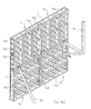
- Fig. 9 a pattern of obliquely to the walls 100 and 102 extending, at right angles intersecting stiffening ribs 104 which are integrally formed on the back of the front wall 106 of the filling element 6.
- the filling element 6 is designed for injection molding in such a way that the part of the injection mold positioned inside the box can be pulled out in a direction perpendicular to the formwork surface 8 and the outer side surfaces of the box are formed by parts of the injection mold which respectively extend in the direction to move away from the box interior.
- the screws 40 are not screwed directly into the material of the filling elements 6. Rather, for example, rectangular threaded plates 108 are provided with central opening 110, which are inserted by small slots 112 in the longitudinal walls 100 of the relevant filling element 6 cross-section. In front of the opening 110 of the relevant tab 108, there is a pair of half openings 114, each formed in the end region of the transverse wall 102 of the two adjacent filling elements. Through the solid hole thus formed, the screw in question 40 can be screwed into the opening 110 of the tab 108.
- each filling element 6 on the one hand and each of the edge beam 4 connected thereto on the other hand and between each adjacent filling elements 6 means in the direction of the height h of the formwork panel 2 effective are present for positive fixing of the respective relative position of the adjacent components.
- each Eckausbianache 120 are present, which extend in the transverse direction of the filling element.
- the corner recesses 120 are present at the location of the transition from longitudinal wall 100 to transverse wall 102; between the two longitudinal walls 100, the respective transverse wall 102 is anyway a bit lower, so that they do not have to have corner recess 120 at the top.
- the Eckauslangisme are present both on the front side and on the back of the filling element 6.
- shear pins 122 are present, which are inserted into matching openings 124 of the local longitudinal wall 100 of the respective filling element 6.
- the openings 124 can be formed as stepped openings, so that the shear pins 122 can be inserted into the opening 124 until they bear against a shoulder.
- the openings 124 pass through stiffening ribs 148, which are respectively present at this point on the outside of the longitudinal wall 100.
- the shear pins 122 may also be tubular hollow pins. In this case, you can push through a bolt that is longer than the hollow pin, see Fig. 14b , Alternatively, one could work with interlocking mating of longitudinal projections and longitudinal recesses on the longitudinal walls 100 of adjacent filling elements.
- the longitudinal walls 100 of the filling elements are e.g. centrally handle openings 126 available so that you can reach in there for convenient handling of the formwork panels by hand.
- the described means for the positive fixing of relative positions are designed such that, in particular, on the front side of the formwork panel 2, the formwork surface without height level without offset passes from the front surface of the respective filling element in the front surface of the adjacent filling element 6 or in the subsequent front surface of the connected edge support 4.
- edge beams are here cut for the sake of clarity and drawn too short.
- the edge support 4 are cut through after two filling elements and also cut off left-top; in truth, they extend further to the left-up.
- Fig. 10 shown portion of the attached connection lock 50 is quite analogous to the situation in the first embodiment, Fig. 5
- the in Fig. 11 shown region of the attached clamping anchor is quite analogous as in the first embodiment, Fig. 6 , Both 10 and 11 is drawn at the points 130, the alternative that the filling elements 6 are connected without means for mutual positive-locking fixing to the respective edge support 4.
- each of the rear flange 12 of the edge support 4 has the same width b as each side wall 100 of the filling element 6 in the rear end region.
- connecting locks 50 the same applies to the first embodiment; one can optionally create edge girders / edge girder connections, gusset sidewall / gusset sidewall joints, and girder / gusset sidewall joints.
- Fig. 14a illustrates, as it were, at a glance and in one of many possible configurations, such as formwork panels 2 of the second embodiment, to assemble into a connected formwork panel assembly.
- the first connection lock 50a is shown, which connects the two adjacent formwork panels 2a and 2b to each other by the first connection lock 50a two adjacent edge support 4, the rear flanges 12 engages under / interlocking, clamped together.
- the first connection lock has a base 140 in the form of a square tube.
- the base 140 has a width that is approximately twice the width of a filler sidewall 100 in its rear end region.
- the jaws 57 of each jaw 52 and 54, respectively, are spaced so far apart that they have room for two side walls 100 in the rear end portion thereof.
- a second connection lock 50b is shown, which connects two adjacent formwork panels 2c and 2d with each other by the second connection lock 50b two adjacent filler side walls 100 clamped together.
- the connecting locks 50a and 50b are equal to each other.
- the base 140 is long enough that it is supported with its end regions in each case on a next-coming filler element side wall 100.
- the four jaws 57 engage in four elongated engagement holes 136 in the side walls 100, and in the respective side wall 100, the engagement holes 136 are provided in pairs corresponding to the position of the jaws 57.
- a plurality of pairs of engagement holes 136 are provided along the respective side wall, at those locations where stiffening ribs 148 are so as to have selection in the mounting location of the second connection lock 50b.
- the claws have inclined surfaces 56, as in Fig. 5 and Fig. 10 gezeichet; cooperating with the end not far from the rear end of the side wall 100 of the respective engagement opening 136, the jaws 52 and 54 bias the two side walls 100 engaged and press the two rear end portions against the base 140 for height alignment.
- Each third connecting lock 50c connects the first switching board 2a to the third switching board 2c and the second switching board 2b to the fourth switching board 2d, by a edge support 4 of the switching board 2c and 2d with a filler sidewall 100 at the end of the adjacent board 2a and 2b are clamped together.
- the connecting locks 50a, 50b, 50c are equal to each other.
- the base 140 rests on a pair of side walls 100 in the rear end region thereof; the claws 57 sandwich the two side walls 100 in the rear end portion thereof.
- the base 140 On the other side of the pair of jaws 52 and 54, the base 140 is long enough so that it rests in its end region on the next side wall 100 in its rear end region.
- One of the jaws 52 and 54 engages behind / engages with their two claws 57, the rear flange 12 of the respective edge support 4.
- the two jaws 57 engage in a pair of engagement holes 136, as in the example of the second connection lock 5b described above.
- inter-engaging longitudinal projection on the edge support 4 or on side wall 100
- engagement openings 136 are alternative means for cooperation with a connection lock 50. Depending on which means are more practicable, the designer can choose.
- Engaging openings 136 can also according to the first embodiment Fig. 1 to 8 be provided.
- Fig. 14b The possibility is shown graphically that instead of the connecting locks 50 of Fig. 14a Bolt 142 with an axially extending slot provides, in each of which a wedge 144 is inserted.
- the wedge 144 is driven so far into the slot that either two edge support 4 or two side walls 100 or a rim support 4 and a side wall 100 between the bolt head and the wedge 144 are clamped together.
- the respective pin 142 is defined by a pair of apertures 124 (or, more concretely, by the hollow pin 124 incorporated therein Pair of openings 124 inserted) inserted.
- the bolt 142 is inserted through a pair of openings 146 in two adjacent edge beams.
- the bolt 142 passes partly through an opening 124 and partly through an opening 146.
- connection locks 50 or bolts 142 with wedge 144 or bolts can be used alternatively and depending on current requirements.
- the compounds can be solved again immediately after completion of the respective concreting task, or it is also possible to keep several formwork panels 2 connected to one another for an extended period of time, e.g. if you have a larger length of shuttering that was not available at the site, composed of two or more shorter formwork panels 2 and this larger formwork length is later needed again at a different location on the site.
- At least the smaller to medium formats of the formwork panel 2 according to the invention can be made available with such a low weight that a single man can pick them up and carry them to the installation site in the overall formwork. This usually applies to a limit of 40 kg. It has been found that, for example, a 60 cm wide and 270 cm long board 2 in the construction of the second embodiment according to Fig. 9 to 13 weighing less than 40 kg.
- connection lock 50 or a bolt 142 or a bolt is to be attached on the inside (i.e. a metal strip.
Landscapes
- Engineering & Computer Science (AREA)
- Architecture (AREA)
- Mechanical Engineering (AREA)
- Civil Engineering (AREA)
- Structural Engineering (AREA)
- Forms Removed On Construction Sites Or Auxiliary Members Thereof (AREA)
Claims (15)
- Tableau de distribution de bétonnage (2), qui offre une surface de coffrage (8) avec son côté avant, présentant les caractéristiques suivantes :(a) le tableau de distribution (2) est composé d'éléments de tableau de distribution (4 ; 6) ;(b) les éléments de tableau de distribution comportent un premier support de bordure (4) et un deuxième support de bordure (4), lesquels s'étendent le long de deux bordures se faisant face du tableau de distribution (2) ;(c) des éléments de remplissage (6) en matière plastique font partie des éléments de tableau de distribution, lesquels éléments de remplissage s'étendent respectivement du premier support de bordure (4) au deuxième support de bordure (4) ; et(d) les éléments de remplissage (6) font partie intégrante aussi bien de la structure porteuse du tableau de distribution (2) que, respectivement par leur côté frontal, de la surface de coffrage (8) du tableau de distribution (2) ;
caractérisé en ce que les éléments de remplissage (6) sont assemblés de manière amovible au premier support de bordure (4) et au deuxième support de bordure (4) respectivement à l'aide de vis (40), de rivets ou d'éléments d'assemblage par serrage, dans lequel sont présents des moyens (10, 12, 120) ayant une action en direction de la hauteur (h) du tableau de distribution (2) et servant à bloquer par complémentarité de forme la position relative respective de l'élément de remplissage (6) et du support de bordure (4). - Tableau de distribution selon la revendication 1,
caractérisé en ce que les deux supports de bordure (4) également font partie intégrante au niveau de leur côté frontal de la surface de coffrage (8) du tableau de distribution (2). - Tableau de distribution selon la revendication 1 ou 2,
caractérisé en ce que les moyens (10, 12, 120) destiné au blocage par complémentarité de forme sont réalisés sous la forme d'un évidement d'angle s'étendant respectivement le long du support de bordure concerné, dans lequel est logée respectivement une zone de bordure de l'élément de remplissage concerné, ou sous la forme d'un évidement d'angle (120) s'étendant respectivement dans la direction transversale de 1'élément de remplissage (6) concerné, dans lequel est logée respectivement une zone de bordure du support de bordure (4) concerné. - Tableau de distribution selon l'une quelconque des revendications 1 à 3, caractérisé en ce que les deux supports de bordure (4) et les éléments de remplissage (6) présentent tous essentiellement la même hauteur (h).
- Tableau de distribution selon l'une quelconque des revendications 1 à 4,
caractérisé en ce que les deux supports de bordure (4) présentent respectivement une section transversale à la manière d'un double profilé en T. - Tableau de distribution selon l'une quelconque des revendications 1 à 5,
caractérisé en ce que les deux supports de bordure (4) sont réalisés, respectivement au niveau de leur côté tourné vers les éléments de remplissage (6), soit respectivement avec une partie faisant saillie longitudinale (12), laquelle est réalisée pour l'engrènement par le bas avec un verrou d'assemblage (50), aux fins de l'assemblage de deux tableaux de distribution (2) adjacents, soit respectivement avec une série d'orifices d'engrènement, qui sont réalisés respectivement pour l'engrènement avec une griffe d'un verrou d'assemblage aux fins de l'assemblage de deux tableaux de distribution adjacents. - Tableau de distribution selon l'une quelconque des revendications 1 à 6,
caractérisé en ce que les deux supports de bordure (4) présentent respectivement, dans leur zone de bordure opposée aux éléments de remplissage (6), au moins un demi-trou (62), qui s'étend à angle droit par rapport à la surface de coffrage (8). - Tableau de distribution selon l'une quelconque des revendications 1 à 7,
caractérisé en ce que les deux supports de bordure (4) présentent respectivement une longueur correspondant à un multiple d'un nombre entier des largeurs d'élément de remplissage égales les unes aux autres. - Tableau de distribution selon l'une quelconque des revendications 1 à 8,
caractérisé en ce que soit tous les éléments de remplissage (6), soit tous les éléments de remplissage (6) à l'exception de deux éléments de remplissage d'extrémité sont réalisés essentiellement de manière identique les uns par rapport aux autres. - Tableau de distribution selon l'une quelconque des revendications 1 à 9,
caractérisé en ce que sont présents des moyens ayant une action en direction de la hauteur (h) du tableau de distribution (2) et servant à bloquer par complémentarité de forme la position relative respective d'éléments de remplissage adjacents, de préférence sous la forme de goupilles de cisaillement (122) insérées ou sous la forme d'un engrènement mutuel de parties faisant saillie et de retraits allongés. - Tableau de distribution selon l'une quelconque des revendications 1 à 10,
caractérisé en ce qu'au moins les deux éléments de remplissage d'extrémité (6) présentent respectivement une paroi latérale (100) dans la zone de bordure du tableau de distribution (2), et en ce que lesdites parois latérales (100) sont réalisées soit respectivement , au niveau de leur côté tourné vers le centre du tableau de distribution, avec une partie faisant saillie longitudinale, laquelle est réalisée pour l'engrènement par le bas avec un verrou d'assemblage aux fins de l'assemblage de deux tableaux de distribution adjacents, ou respectivement avec une série d'orifices d'engrènement (136), lesquels sont réalisés respectivement pour l'engrènement avec une griffe (57) d'un verrou d'assemblage aux fins de l'assemblage de deux tableaux de distribution (2) adjacents. - Tableau de distribution selon l'une quelconque des revendications 1 à 11,
caractérisé en ce que les éléments de remplissage (6) présentent des orifices (124) servant à coopérer avec des accessoires de coffrage, tels que des étais (90) et des consoles (70). - Tableau de distribution selon l'une quelconque des revendications 1 à 12,
caractérisé en ce que les éléments de remplissage (6) présentent respectivement des nervures de renforcement (104) au niveau du côté arrière de la paroi (106) formant la surface de coffrage (8). - Tableau de distribution selon l'une quelconque des revendications 1 à 13,
caractérisé en ce que les deux supports de bordure (4) sont en métal, sont de préférence des profilés en aluminium extrudés, ou sont en matière plastique de préférence renforcée par des fibres. - Tableau de distribution selon l'une quelconque des revendications 1 à 14,
caractérisé en ce que les éléments de remplissage (6) sont en matière plastique renforcée par des fibres et/ou sont des parties en matière plastique coulées par injection.
Applications Claiming Priority (2)
| Application Number | Priority Date | Filing Date | Title |
|---|---|---|---|
| DE102009036647A DE102009036647A1 (de) | 2009-08-07 | 2009-08-07 | Betonierungs-Schaltafel |
| PCT/EP2010/061507 WO2011015660A1 (fr) | 2009-08-07 | 2010-08-06 | Tableau de distribution de bétonnage |
Publications (2)
| Publication Number | Publication Date |
|---|---|
| EP2462296A1 EP2462296A1 (fr) | 2012-06-13 |
| EP2462296B1 true EP2462296B1 (fr) | 2014-05-21 |
Family
ID=42985614
Family Applications (1)
| Application Number | Title | Priority Date | Filing Date |
|---|---|---|---|
| EP10740651.4A Not-in-force EP2462296B1 (fr) | 2009-08-07 | 2010-08-06 | Tableau de distribution de bétonnage |
Country Status (3)
| Country | Link |
|---|---|
| EP (1) | EP2462296B1 (fr) |
| DE (1) | DE102009036647A1 (fr) |
| WO (1) | WO2011015660A1 (fr) |
Cited By (3)
| Publication number | Priority date | Publication date | Assignee | Title |
|---|---|---|---|---|
| WO2019023745A1 (fr) * | 2017-08-01 | 2019-02-07 | Wangwealth Pty Ltd | Cadre de panneau de coffrage |
| CN109653488A (zh) * | 2019-01-14 | 2019-04-19 | 广西汉瑞金属科技有限公司 | 一种建筑模板支撑体系的模板单元及其安装方法 |
| US12264489B1 (en) | 2024-06-07 | 2025-04-01 | Providencia Composites, LLC | Environmentally friendly reusable structure for use in construction |
Families Citing this family (13)
| Publication number | Priority date | Publication date | Assignee | Title |
|---|---|---|---|---|
| DE102013107303B4 (de) | 2013-07-10 | 2024-06-06 | Polytech Gmbh | Schaltafel für Betonierungsschalungen |
| FR3010723B1 (fr) * | 2013-09-13 | 2017-04-07 | Sateco Sa | Banche de coffrage comportant un element de support pour un coffrage auxiliaire |
| US11976483B2 (en) | 2016-06-24 | 2024-05-07 | Apache Industrial Services, Inc | Modular posts of an integrated construction system |
| US11624196B2 (en) | 2016-06-24 | 2023-04-11 | Apache Industrial Services, Inc | Connector end fitting for an integrated construction system |
| US12195961B2 (en) | 2016-06-24 | 2025-01-14 | Apache Industrial Services, Inc. | Formwork system |
| US11306492B2 (en) | 2016-06-24 | 2022-04-19 | Apache Industrial Services, Inc | Load bearing components and safety deck of an integrated construction system |
| US10415262B2 (en) | 2016-06-24 | 2019-09-17 | Apache Industrial Services, Inc. | Modular ledgers of an integrated construction system |
| US10472823B2 (en) | 2016-06-24 | 2019-11-12 | Apache Industrial Services, Inc. | Formwork system |
| US10465399B2 (en) | 2016-06-24 | 2019-11-05 | Apache Industrial Services, Inc. | Integrated construction system |
| DE102019002356A1 (de) * | 2019-04-01 | 2020-10-01 | Polytech Gmbh | Tragstruktur in Kunststoffbauweise für Schalungspaneel |
| PH12021050086A1 (en) * | 2021-01-04 | 2022-08-01 | Yuan Tai Chin | Connector assembly for beam and slab construction |
| WO2023011772A1 (fr) * | 2021-08-05 | 2023-02-09 | Peri Se | Panneau de coffrage et système pour le coffrage d'un élément de paroi |
| DE102021120438A1 (de) * | 2021-08-05 | 2023-02-09 | Peri Se | System zur Schalung eines Wandelementes mit einem frei stehenden Gerüstabschnitt |
Family Cites Families (5)
| Publication number | Priority date | Publication date | Assignee | Title |
|---|---|---|---|---|
| DE801473C (de) * | 1949-12-22 | 1951-01-08 | Kaercher Fa Alfred | Schalungstafel aus Metall |
| CH679230A5 (en) * | 1988-12-22 | 1992-01-15 | Rolf Zollinger | Concrete shuttering - has tough elastic plank-type components with diverging air passages |
| JPH06212785A (ja) * | 1993-01-19 | 1994-08-02 | Shinko Kigyo Kk | 建築型枠用の合成樹脂製単位枠 |
| JPH08312131A (ja) * | 1995-03-15 | 1996-11-26 | Nsp Corp | コンクリート型枠 |
| DE10330462A1 (de) * | 2003-07-05 | 2005-01-27 | Peri Gmbh | Einhakbare Spannschlossvorrichtung |
-
2009
- 2009-08-07 DE DE102009036647A patent/DE102009036647A1/de not_active Withdrawn
-
2010
- 2010-08-06 WO PCT/EP2010/061507 patent/WO2011015660A1/fr not_active Ceased
- 2010-08-06 EP EP10740651.4A patent/EP2462296B1/fr not_active Not-in-force
Cited By (3)
| Publication number | Priority date | Publication date | Assignee | Title |
|---|---|---|---|---|
| WO2019023745A1 (fr) * | 2017-08-01 | 2019-02-07 | Wangwealth Pty Ltd | Cadre de panneau de coffrage |
| CN109653488A (zh) * | 2019-01-14 | 2019-04-19 | 广西汉瑞金属科技有限公司 | 一种建筑模板支撑体系的模板单元及其安装方法 |
| US12264489B1 (en) | 2024-06-07 | 2025-04-01 | Providencia Composites, LLC | Environmentally friendly reusable structure for use in construction |
Also Published As
| Publication number | Publication date |
|---|---|
| EP2462296A1 (fr) | 2012-06-13 |
| DE102009036647A1 (de) | 2011-02-17 |
| WO2011015660A1 (fr) | 2011-02-10 |
Similar Documents
| Publication | Publication Date | Title |
|---|---|---|
| EP2462296B1 (fr) | Tableau de distribution de bétonnage | |
| EP3327219B1 (fr) | Plateau de coffrage pour coffrages de béton | |
| DE202009010716U1 (de) | Betonierungs-Schaltafel | |
| EP3398870B1 (fr) | Pallette en plastique avec structure de renfort | |
| DE3838488A1 (de) | Schaltafel | |
| EP1899553B1 (fr) | Systeme de coffrage de plancher | |
| DE2128609A1 (de) | Verstärkte Schalungsplatte fur Be tonschalungen | |
| EP0448120B1 (fr) | Panneau de coffrage pour béton | |
| DE2950138C2 (de) | Plattensystem, insbesondere für Behälter od.dgl. | |
| DE2534160A1 (de) | Schalung zum betonieren | |
| DE3723676C1 (de) | Schalung zum Herstellen von Betonbauteilen | |
| DE29924191U1 (de) | Regal | |
| EP0268197B1 (fr) | Echafaudage, plus spécialement échafaudage pour le bâtiment | |
| EP3502350A1 (fr) | Raccordement de deux éléments de paroi de guidage | |
| DE3013496A1 (de) | System-betonschaltung | |
| DE3700429A1 (de) | Schalungsquerriegel aus stahl zum verbinden mehrerer schalungsplatten-traeger | |
| DE1684303C3 (de) | Schalung für Beton- oder Stahlbetonwände | |
| EP1627978A2 (fr) | Élément de coffrage | |
| DE102022202157A1 (de) | Vorrichtung zum Verbinden von Schalelementen mit einem Gurt und einer Kupplung | |
| EP0674067A1 (fr) | Panneau à cadre pour le coffrage de béton | |
| DE9311710U1 (de) | Schalung zum Herstellen einer Betonplatte | |
| DE20118376U1 (de) | Rahmengestell für einen Schaltschrank | |
| DE2220850C3 (de) | Aus mehreren plattenartigen Teilen aus einem thermoplastischen Strukturschaum zusammengesetzter Sockel für Kabelverteilerschränke | |
| DE102006015054A1 (de) | Deckenschalungssystem | |
| DE20200410U1 (de) | Abschalteil |
Legal Events
| Date | Code | Title | Description |
|---|---|---|---|
| PUAI | Public reference made under article 153(3) epc to a published international application that has entered the european phase |
Free format text: ORIGINAL CODE: 0009012 |
|
| 17P | Request for examination filed |
Effective date: 20120306 |
|
| AK | Designated contracting states |
Kind code of ref document: A1 Designated state(s): AL AT BE BG CH CY CZ DE DK EE ES FI FR GB GR HR HU IE IS IT LI LT LU LV MC MK MT NL NO PL PT RO SE SI SK SM TR |
|
| 17Q | First examination report despatched |
Effective date: 20120611 |
|
| DAX | Request for extension of the european patent (deleted) | ||
| GRAP | Despatch of communication of intention to grant a patent |
Free format text: ORIGINAL CODE: EPIDOSNIGR1 |
|
| INTG | Intention to grant announced |
Effective date: 20130906 |
|
| GRAS | Grant fee paid |
Free format text: ORIGINAL CODE: EPIDOSNIGR3 |
|
| GRAA | (expected) grant |
Free format text: ORIGINAL CODE: 0009210 |
|
| RAP1 | Party data changed (applicant data changed or rights of an application transferred) |
Owner name: POLYTECH GMBH |
|
| AK | Designated contracting states |
Kind code of ref document: B1 Designated state(s): AL AT BE BG CH CY CZ DE DK EE ES FI FR GB GR HR HU IE IS IT LI LT LU LV MC MK MT NL NO PL PT RO SE SI SK SM TR |
|
| REG | Reference to a national code |
Ref country code: GB Ref legal event code: FG4D Free format text: NOT ENGLISH |
|
| REG | Reference to a national code |
Ref country code: CH Ref legal event code: EP |
|
| REG | Reference to a national code |
Ref country code: AT Ref legal event code: REF Ref document number: 669702 Country of ref document: AT Kind code of ref document: T Effective date: 20140615 |
|
| REG | Reference to a national code |
Ref country code: IE Ref legal event code: FG4D Free format text: LANGUAGE OF EP DOCUMENT: GERMAN |
|
| REG | Reference to a national code |
Ref country code: DE Ref legal event code: R096 Ref document number: 502010007036 Country of ref document: DE Effective date: 20140703 |
|
| REG | Reference to a national code |
Ref country code: NL Ref legal event code: VDEP Effective date: 20140521 |
|
| REG | Reference to a national code |
Ref country code: LT Ref legal event code: MG4D |
|
| PG25 | Lapsed in a contracting state [announced via postgrant information from national office to epo] |
Ref country code: NO Free format text: LAPSE BECAUSE OF FAILURE TO SUBMIT A TRANSLATION OF THE DESCRIPTION OR TO PAY THE FEE WITHIN THE PRESCRIBED TIME-LIMIT Effective date: 20140821 Ref country code: IS Free format text: LAPSE BECAUSE OF FAILURE TO SUBMIT A TRANSLATION OF THE DESCRIPTION OR TO PAY THE FEE WITHIN THE PRESCRIBED TIME-LIMIT Effective date: 20140921 Ref country code: LT Free format text: LAPSE BECAUSE OF FAILURE TO SUBMIT A TRANSLATION OF THE DESCRIPTION OR TO PAY THE FEE WITHIN THE PRESCRIBED TIME-LIMIT Effective date: 20140521 Ref country code: FI Free format text: LAPSE BECAUSE OF FAILURE TO SUBMIT A TRANSLATION OF THE DESCRIPTION OR TO PAY THE FEE WITHIN THE PRESCRIBED TIME-LIMIT Effective date: 20140521 Ref country code: GR Free format text: LAPSE BECAUSE OF FAILURE TO SUBMIT A TRANSLATION OF THE DESCRIPTION OR TO PAY THE FEE WITHIN THE PRESCRIBED TIME-LIMIT Effective date: 20140822 |
|
| PG25 | Lapsed in a contracting state [announced via postgrant information from national office to epo] |
Ref country code: ES Free format text: LAPSE BECAUSE OF FAILURE TO SUBMIT A TRANSLATION OF THE DESCRIPTION OR TO PAY THE FEE WITHIN THE PRESCRIBED TIME-LIMIT Effective date: 20140521 Ref country code: LV Free format text: LAPSE BECAUSE OF FAILURE TO SUBMIT A TRANSLATION OF THE DESCRIPTION OR TO PAY THE FEE WITHIN THE PRESCRIBED TIME-LIMIT Effective date: 20140521 Ref country code: HR Free format text: LAPSE BECAUSE OF FAILURE TO SUBMIT A TRANSLATION OF THE DESCRIPTION OR TO PAY THE FEE WITHIN THE PRESCRIBED TIME-LIMIT Effective date: 20140521 Ref country code: SE Free format text: LAPSE BECAUSE OF FAILURE TO SUBMIT A TRANSLATION OF THE DESCRIPTION OR TO PAY THE FEE WITHIN THE PRESCRIBED TIME-LIMIT Effective date: 20140521 Ref country code: PL Free format text: LAPSE BECAUSE OF FAILURE TO SUBMIT A TRANSLATION OF THE DESCRIPTION OR TO PAY THE FEE WITHIN THE PRESCRIBED TIME-LIMIT Effective date: 20140521 |
|
| PG25 | Lapsed in a contracting state [announced via postgrant information from national office to epo] |
Ref country code: PT Free format text: LAPSE BECAUSE OF FAILURE TO SUBMIT A TRANSLATION OF THE DESCRIPTION OR TO PAY THE FEE WITHIN THE PRESCRIBED TIME-LIMIT Effective date: 20140922 |
|
| PG25 | Lapsed in a contracting state [announced via postgrant information from national office to epo] |
Ref country code: RO Free format text: LAPSE BECAUSE OF FAILURE TO SUBMIT A TRANSLATION OF THE DESCRIPTION OR TO PAY THE FEE WITHIN THE PRESCRIBED TIME-LIMIT Effective date: 20140521 Ref country code: SK Free format text: LAPSE BECAUSE OF FAILURE TO SUBMIT A TRANSLATION OF THE DESCRIPTION OR TO PAY THE FEE WITHIN THE PRESCRIBED TIME-LIMIT Effective date: 20140521 Ref country code: CZ Free format text: LAPSE BECAUSE OF FAILURE TO SUBMIT A TRANSLATION OF THE DESCRIPTION OR TO PAY THE FEE WITHIN THE PRESCRIBED TIME-LIMIT Effective date: 20140521 Ref country code: DK Free format text: LAPSE BECAUSE OF FAILURE TO SUBMIT A TRANSLATION OF THE DESCRIPTION OR TO PAY THE FEE WITHIN THE PRESCRIBED TIME-LIMIT Effective date: 20140521 Ref country code: EE Free format text: LAPSE BECAUSE OF FAILURE TO SUBMIT A TRANSLATION OF THE DESCRIPTION OR TO PAY THE FEE WITHIN THE PRESCRIBED TIME-LIMIT Effective date: 20140521 |
|
| REG | Reference to a national code |
Ref country code: DE Ref legal event code: R097 Ref document number: 502010007036 Country of ref document: DE |
|
| PG25 | Lapsed in a contracting state [announced via postgrant information from national office to epo] |
Ref country code: NL Free format text: LAPSE BECAUSE OF FAILURE TO SUBMIT A TRANSLATION OF THE DESCRIPTION OR TO PAY THE FEE WITHIN THE PRESCRIBED TIME-LIMIT Effective date: 20140521 |
|
| PLBE | No opposition filed within time limit |
Free format text: ORIGINAL CODE: 0009261 |
|
| STAA | Information on the status of an ep patent application or granted ep patent |
Free format text: STATUS: NO OPPOSITION FILED WITHIN TIME LIMIT |
|
| PG25 | Lapsed in a contracting state [announced via postgrant information from national office to epo] |
Ref country code: LU Free format text: LAPSE BECAUSE OF FAILURE TO SUBMIT A TRANSLATION OF THE DESCRIPTION OR TO PAY THE FEE WITHIN THE PRESCRIBED TIME-LIMIT Effective date: 20140806 Ref country code: MC Free format text: LAPSE BECAUSE OF FAILURE TO SUBMIT A TRANSLATION OF THE DESCRIPTION OR TO PAY THE FEE WITHIN THE PRESCRIBED TIME-LIMIT Effective date: 20140521 |
|
| REG | Reference to a national code |
Ref country code: CH Ref legal event code: PL |
|
| 26N | No opposition filed |
Effective date: 20150224 |
|
| GBPC | Gb: european patent ceased through non-payment of renewal fee |
Effective date: 20140821 |
|
| PG25 | Lapsed in a contracting state [announced via postgrant information from national office to epo] |
Ref country code: LI Free format text: LAPSE BECAUSE OF NON-PAYMENT OF DUE FEES Effective date: 20140831 Ref country code: IT Free format text: LAPSE BECAUSE OF FAILURE TO SUBMIT A TRANSLATION OF THE DESCRIPTION OR TO PAY THE FEE WITHIN THE PRESCRIBED TIME-LIMIT Effective date: 20140521 Ref country code: BE Free format text: LAPSE BECAUSE OF NON-PAYMENT OF DUE FEES Effective date: 20140831 Ref country code: CH Free format text: LAPSE BECAUSE OF NON-PAYMENT OF DUE FEES Effective date: 20140831 |
|
| REG | Reference to a national code |
Ref country code: IE Ref legal event code: MM4A |
|
| REG | Reference to a national code |
Ref country code: FR Ref legal event code: ST Effective date: 20150430 |
|
| REG | Reference to a national code |
Ref country code: DE Ref legal event code: R097 Ref document number: 502010007036 Country of ref document: DE Effective date: 20150224 |
|
| PG25 | Lapsed in a contracting state [announced via postgrant information from national office to epo] |
Ref country code: GB Free format text: LAPSE BECAUSE OF NON-PAYMENT OF DUE FEES Effective date: 20140821 Ref country code: SI Free format text: LAPSE BECAUSE OF FAILURE TO SUBMIT A TRANSLATION OF THE DESCRIPTION OR TO PAY THE FEE WITHIN THE PRESCRIBED TIME-LIMIT Effective date: 20140521 |
|
| PG25 | Lapsed in a contracting state [announced via postgrant information from national office to epo] |
Ref country code: IE Free format text: LAPSE BECAUSE OF NON-PAYMENT OF DUE FEES Effective date: 20140806 Ref country code: FR Free format text: LAPSE BECAUSE OF NON-PAYMENT OF DUE FEES Effective date: 20140901 |
|
| PG25 | Lapsed in a contracting state [announced via postgrant information from national office to epo] |
Ref country code: SM Free format text: LAPSE BECAUSE OF FAILURE TO SUBMIT A TRANSLATION OF THE DESCRIPTION OR TO PAY THE FEE WITHIN THE PRESCRIBED TIME-LIMIT Effective date: 20140521 |
|
| PG25 | Lapsed in a contracting state [announced via postgrant information from national office to epo] |
Ref country code: BG Free format text: LAPSE BECAUSE OF FAILURE TO SUBMIT A TRANSLATION OF THE DESCRIPTION OR TO PAY THE FEE WITHIN THE PRESCRIBED TIME-LIMIT Effective date: 20140521 Ref country code: CY Free format text: LAPSE BECAUSE OF FAILURE TO SUBMIT A TRANSLATION OF THE DESCRIPTION OR TO PAY THE FEE WITHIN THE PRESCRIBED TIME-LIMIT Effective date: 20140521 Ref country code: MT Free format text: LAPSE BECAUSE OF FAILURE TO SUBMIT A TRANSLATION OF THE DESCRIPTION OR TO PAY THE FEE WITHIN THE PRESCRIBED TIME-LIMIT Effective date: 20140521 |
|
| PG25 | Lapsed in a contracting state [announced via postgrant information from national office to epo] |
Ref country code: TR Free format text: LAPSE BECAUSE OF FAILURE TO SUBMIT A TRANSLATION OF THE DESCRIPTION OR TO PAY THE FEE WITHIN THE PRESCRIBED TIME-LIMIT Effective date: 20140521 Ref country code: HU Free format text: LAPSE BECAUSE OF FAILURE TO SUBMIT A TRANSLATION OF THE DESCRIPTION OR TO PAY THE FEE WITHIN THE PRESCRIBED TIME-LIMIT; INVALID AB INITIO Effective date: 20100806 |
|
| REG | Reference to a national code |
Ref country code: AT Ref legal event code: MM01 Ref document number: 669702 Country of ref document: AT Kind code of ref document: T Effective date: 20150806 |
|
| PG25 | Lapsed in a contracting state [announced via postgrant information from national office to epo] |
Ref country code: AT Free format text: LAPSE BECAUSE OF NON-PAYMENT OF DUE FEES Effective date: 20150806 |
|
| REG | Reference to a national code |
Ref country code: DE Ref legal event code: R082 Ref document number: 502010007036 Country of ref document: DE Representative=s name: SCHMITT-NILSON SCHRAUD WAIBEL WOHLFROM PATENTA, DE |
|
| PG25 | Lapsed in a contracting state [announced via postgrant information from national office to epo] |
Ref country code: MK Free format text: LAPSE BECAUSE OF FAILURE TO SUBMIT A TRANSLATION OF THE DESCRIPTION OR TO PAY THE FEE WITHIN THE PRESCRIBED TIME-LIMIT Effective date: 20140521 |
|
| PG25 | Lapsed in a contracting state [announced via postgrant information from national office to epo] |
Ref country code: AL Free format text: LAPSE BECAUSE OF FAILURE TO SUBMIT A TRANSLATION OF THE DESCRIPTION OR TO PAY THE FEE WITHIN THE PRESCRIBED TIME-LIMIT Effective date: 20140521 |
|
| PGFP | Annual fee paid to national office [announced via postgrant information from national office to epo] |
Ref country code: DE Payment date: 20211027 Year of fee payment: 12 |
|
| REG | Reference to a national code |
Ref country code: DE Ref legal event code: R119 Ref document number: 502010007036 Country of ref document: DE |
|
| PG25 | Lapsed in a contracting state [announced via postgrant information from national office to epo] |
Ref country code: DE Free format text: LAPSE BECAUSE OF NON-PAYMENT OF DUE FEES Effective date: 20230301 |