EP0448120B1 - Panneau de coffrage pour béton - Google Patents
Panneau de coffrage pour béton Download PDFInfo
- Publication number
- EP0448120B1 EP0448120B1 EP91104549A EP91104549A EP0448120B1 EP 0448120 B1 EP0448120 B1 EP 0448120B1 EP 91104549 A EP91104549 A EP 91104549A EP 91104549 A EP91104549 A EP 91104549A EP 0448120 B1 EP0448120 B1 EP 0448120B1
- Authority
- EP
- European Patent Office
- Prior art keywords
- shuttering
- panel
- shuttering panel
- formwork
- component
- Prior art date
- Legal status (The legal status is an assumption and is not a legal conclusion. Google has not performed a legal analysis and makes no representation as to the accuracy of the status listed.)
- Expired - Lifetime
Links
Images


Classifications
-
- E—FIXED CONSTRUCTIONS
- E04—BUILDING
- E04G—SCAFFOLDING; FORMS; SHUTTERING; BUILDING IMPLEMENTS OR AIDS, OR THEIR USE; HANDLING BUILDING MATERIALS ON THE SITE; REPAIRING, BREAKING-UP OR OTHER WORK ON EXISTING BUILDINGS
- E04G9/00—Forming or shuttering elements for general use
- E04G9/02—Forming boards or similar elements
- E04G9/05—Forming boards or similar elements the form surface being of plastics
-
- E—FIXED CONSTRUCTIONS
- E04—BUILDING
- E04G—SCAFFOLDING; FORMS; SHUTTERING; BUILDING IMPLEMENTS OR AIDS, OR THEIR USE; HANDLING BUILDING MATERIALS ON THE SITE; REPAIRING, BREAKING-UP OR OTHER WORK ON EXISTING BUILDINGS
- E04G9/00—Forming or shuttering elements for general use
- E04G9/02—Forming boards or similar elements
Definitions
- frame formwork panels used today are designed as frame formwork panels. They consist essentially of a plate-like formlining, which is often designed as a particle board with a smooth surface, and a stiffening frame made of metal profiles on the back.
- the manufacture of the profile frame in particular is complex because the metal profiles have to be cut to length, welded to one another and color-coated.
- frame formwork panels have a relatively high weight per unit area of formwork skin, so that the formwork panels, apart from very small formwork panel sizes, have to be moved by crane.
- a concrete formwork panel with the features (a) and (b) specified at the outset is known from document DE-A-2 253 588.
- conventional frame formwork panels without a plate-like rear area it is known per se to clamp formwork panels to one another by means of connecting locks which encompass the edge metal profiles of adjacent formwork panels (EP-A-0 304 950).
- the concrete formwork panel according to the invention has a lower weight per unit area of formlining. As a result, larger formwork panels can be moved and set up by hand than before. Transport to the construction site is made easier. There are also opportunities for significantly more efficient and cost-effective production.
- the formwork panel preferably has edge components that are connected to the support structure at least along two opposite edges.
- the components mentioned including the plate-like rear component or rear area, which is not conventionally present, are included in the static load-bearing function of the entire panel structure, so that optimized static conditions and material utilization result. This results in weight savings.
- the struts formed by the intermediate area or spacing component are preferably diagonal struts of alternating direction of inclination.
- the control panel is, like conventional control panels, preferably rectangular or square in plan view.
- the components mentioned need not necessarily be in one piece, although this is preferred for each of the components.
- Edge components and / or rear channels are preferably provided for attaching connecting locks along four edges of the formwork panel.
- the formwork panel consists predominantly or entirely of plastic.
- other materials are also possible, in particular wood, metal etc.
- a construction is very particularly preferred in which the formwork panel - having no pronounced edge components or without the edge components or including the edge components on two opposite edges - consists integrally of extruded plastic. It is possible to attach two or four edge components, in particular made of metal, to this integral, extruded plastic part, for example by gluing, riveting or the like. Alternatively, it is possible to manufacture the components mentioned at the beginning and then to connect them to one another by gluing, riveting, plastic welding or the like. Another preferred alternative is to manufacture the front component and the rear component from a sheet metal plate and to produce the spacer component from a zigzag-shaped sheet metal plate; these components are then firmly connected to one another, in particular by spot welding or riveting.
- edge regions of the formwork panel can be formed by parts of the front component, the rear component and / or the spacing component.
- edge components in particular from thicker sheet metal, and to connect them to the other components.
- the formwork can be produced in the manner of a lattice girder by extrusion despite the cross section, since the cross section does not change along the formwork panel. This also simplifies production in the metal construction of the formwork panel.
- the static structure of a box girder is obtained in a second section at right angles to the cross section mentioned.
- the front component, the rear component and the spacer component are formed by a, preferably integral, composite plate. Suitable composite panels can be produced very efficiently.
- the described edge components can preferably be attached to the composite panel.
- the rear channels mentioned above are designed so that connecting locks for aligned, aligned clamping of adjacent formwork panels can be attached there. If the channels have undercuts, the channels are preferably undercut on their sides facing the edge. The undercuts are preferably V-shaped. The channels can also be used to manually grip the formwork panel.
- External, longitudinal grooves are preferably provided on at least two opposite side surfaces.
- mutual contact areas arise between two adjacent formwork panels, namely an investment area in the front area and another investment area in the rear area.
- the support structure has cavities
- the cavities can preferably be foamed, at least in the region adjacent to the formwork panel front.
- the material walls of the spacer component can be provided closer together there.
- the formwork panel preferably has half-holes in its edge region, which are open to its rear side and to its front side, so that when formwork panels are placed next to one another, complete holes result through the mutual supplementation of half-holes, through which rods can be inserted.
- These are primarily fixing bars for fixing the spatial position of the formwork panels for concreting and spacer bars for fixing the mutual spacing of opposing formwork panels when concreting walls or the like.
- the formwork panels can have an overall angular shape, in particular for concreting square columns or concreting walls that converge at an angle or at right angles.
- Suitable plastics for manufacturing the formwork panel are familiar to the person skilled in the art.
- PVC and fiber-reinforced plastics are just a few examples among many possible ones. If the material aluminum has been mentioned above, this obviously does not only mean pure aluminum, but also includes suitable aluminum alloys.
- the invention further relates to a concrete formwork which has a plurality of formwork panels according to the invention which are clamped together by means of connecting locks attached on the rear.
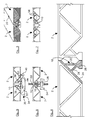
- the formwork panel 2 shown in FIG. 1 is made of extruded plastic, the direction of extrusion being perpendicular to the plane of the drawing.
- the formwork panel 2 essentially consists of a front component 4 in the form of a plane-parallel plate, a back component 6 in the form of a plane-parallel plate, a spacer component 8 in the form of walls placed in a zigzag shape, and two edge components 10 on two opposite formwork panel edges. Because of the shape of the edge components 10, reference is expressly made to FIG. 1 and also to the remaining figures.
- the rear component 6 is less wide than the front component 4, so that a groove 12 is formed on the back of the formwork panel 2 between an edge component 10 and the back component 6, which extends in the longitudinal direction of the formwork panel 2.
- Each of the two channels 12 is undercut in a V-shape on its side facing the edge, because the rear, widened foot of the edge component 10 merges there into a narrower cross section.
- each of the two edge components 10 has a longitudinal groove 14 on its outside.
- An inclined wall 18 (which can be attributed to the edge component 10 or the spacing component 8) leads obliquely from the V-shaped, bead-like undercut 16 to the next wall of the spacing component 8.
- the formwork panel 2 can also be formed without a pronounced edge component 10.
- the two edge components 10 with the two inclined walls 18 can be omitted altogether. Or you can let the wall closest to the edge of the spacer component 8 run at right angles to the front component 4 and the rear component 6.
- FIG. 3 The illustrated design of the formwork panel 2 is illustrated again by means of a perspective illustration by FIG. 3.
- a hole 20 can also be seen, which is formed by mutually complementing two half-holes.
- the hole 20 is open to the front of the panel 2 and to the rear of the panel 2 and extends at right angles to the level of the panel 2.
- the drawn edge component 10 consists of an aluminum profile.
- the aluminum profile essentially has a first wall 22, which runs at a certain distance from the edge of the formwork panel 2 from its front component 4 to its rear component 6, a second wall that diagonally from the front edge of the formwork panel 2 to the rear of the formwork panel 2 in Distance from the edge thereof, a third wall 26, which extends approximately from the center of the second wall 24 to the rear, widened foot 28, and this rear, widened foot 28.
- the edge component 10 is preferably connected to the rest of the formwork panel 2 in that its second Wall 24 is glued or riveted to a flat inclined wall of the spacing component 8.
- edge components 10 of the type shown in FIG. 4 also on the two end faces of the formwork panel 2, namely behind the drawing plane and in front of the drawing plane , attach.
- edge components 10 of the type shown in FIG. 4 also on the two end faces of the formwork panel 2, namely behind the drawing plane and in front of the drawing plane , attach.
- front component 4, rear component 6 and spacer component 8 must be cut off obliquely on both end faces.
- FIG. 5 illustrates how two adjacent formwork panels 2 can be clamped in alignment with one another in a stable manner by means of a connecting lock or a connecting clip.
- the connecting lock 30 consists essentially of an elongated base part 32 with a hollow rectangular cross section, an elongated wedge element 34 accommodated in the base part 32 and displaceable along the base part 32, and two clamp jaws 36 and 38.
- the one clamp jaw 36 is rigidly attached to the base part 32.
- the other clamp jaw 38 is pivotable about an axis 40 which extends between the two side walls of the base part 32.
- a rear lug 42 of the second clamp jaw 38 is in contact with an inclined surface 44 of the wedge element 34. The further the wedge element 34 is displaced to the right in FIG.
- connection locks preferably connection locks 30 such as that shown in FIG. 5, can be used on all four edges for all-round clamping of adjacent formwork panels 2.
- FIG. 6 illustrates how an externally threaded rod 50 can be inserted into a hole 20 mentioned above.
- the outer channels 14 give enough space for the rod 50 between the rear Feet 28 of the edge components 10 and the front material broadening 52 of the edge components 10.
- a wing nut 54 is shown, which engages with the thread of the rod 50 and is supported on the back of the two feet 28.
- FIG. 7 A variant is illustrated in FIG. 7, in which the cavity of the spacing component 8 closest to the edge has additional, longitudinal walls 56.
- the walls 56 provide additional stiffening there.
- the formwork panel 2 is easier to nail.
- Fig. 8 illustrates that formwork panels 2 according to the invention can be produced in different widths.
- Fig. 8 below illustrates a formwork panel 2 with an angular shape for concreting a right-angled inner corner.
- a formwork panel 2 with an angular shape can be created for concreting an outside corner.
- front component walls, the rear component walls and the spacer component walls do not all have to have the same material thickness as shown in the drawing.
- the front component 4 can be given a greater wall thickness than the rear component 6 and the spacing component 8. It is also possible to vary the wall thickness within the respective component, for example in the middle area of the formwork panel 2 choose larger wall thicknesses than more to the edge.
- the drawn cavities 58 of the supporting structure can be foamed with foam plastic.
- the drawing figures show that the edge components 10 are aligned on the back with the rear component 6.
- the formwork panels according to the invention can be stacked on top of one another in a good parallel manner, because their rear side is also closed, possibly with the exception of the channels 12. If the cavities 58 are foamed or the described end faces of the formwork panel 2 are also closed, no concrete can run into the cavities 58.
- edge components 10 are present, these provide an additional stiffening effect. It is therefore most sensible if the edge components 10 are provided running at least in the direction in which the formwork panel 2 is longer than in the transverse direction which can be seen in the drawing figures.
- Usual dimensions of the formwork panel 2 are a width of up to 1 m or even up to 1.5 m and a thickness of 5 to 10 cm.
- the length of the formwork panel 2 can be chosen practically as desired, with lengths of up to approximately 3 or 4 m generally being considered.
- a structure can also be selected from a correspondingly thick composite panel or sandwich panel, to which two or four edge components 10 are preferably attached.
Landscapes
- Engineering & Computer Science (AREA)
- Architecture (AREA)
- Mechanical Engineering (AREA)
- Civil Engineering (AREA)
- Structural Engineering (AREA)
- Forms Removed On Construction Sites Or Auxiliary Members Thereof (AREA)
- Moulds, Cores, Or Mandrels (AREA)
Claims (13)
- Panneau de coffrage Pour béton (2)(a) présent une structure porteuse de panneau de coffrage avec :- une zone avant (4) se présentant sous forme de plaque et faisant office de peau de coffrage,- une zone arrière (6) sous forme de plaque et,- une zone intermédiaire (8) pontant l'espacement entre la zone avant (4) et la zone arrière (6),(b) la structure porteuse ayant une section transversales du genre d'un support de grille avec des montants s'étendant obliquement et constitués par la zone intermédiaire (8),
caractérisé par,(c) des goulottes (12) de face arrière destinées à la pose de serrures de liaison (30) fixant par serrage des panneaux de coffrage (2) voisins prévus à proximité d'au moins deux bords opposés du panneau de coffrage (2). - Panneau de coffrage (2) selon la revendication 1, caractérisé en ce qu'au moins le long de deux bords opposés du panneau de coffrage (2) sont prévus des composants de bordure (10) reliés à la structure porteuse.
- Panneau de coffrage (2) selon au moins l'une des revendications 1 et 2, caractérisé en ce qu'il est constitué principalement ou complètement en matière synthétique.
- Panneau de coffrage (2) selon la revendication 3, caractérisé en ce qu'il est constitué, de préférence y compris les composants de bordure (10) sur deux bords opposés, intégralement en matière synthétique.
- Panneau de coffrage (2) selon au moins l'une des revendications 1 et 2, caractérisé en ce que la structure porteuse est constituée essentiellement en métal.
- Panneau de coffrage (2) selon la revendication 5, caractérisé en ce que pour la zone intermédiaire (8) est prévue une tôle cintrée sensiblement en zigzag, reliée à la tôle de la zone arrière.
- Panneau de coffrage (2) selon au moins l'une des revendications 2 à 6, caractérisé en ce que les constituants de bordure (10) sont en métal.
- Panneau de coffrage (2) selon au moins l'une des revendications 1 à 7, caractérisé en ce que les goulottes (12) sont dotées d'une contre-dépouille pour les serrures de liaison (30).
- Panneau de coffrage selon au moins l'une des revendications 1 à 8, caractérisé en ce qu'entre la zone avant (4) et la zone arrière (6) existent des espaces creux (58), dont de préférence au moins quelques uns sont comblés de façon alvéolaire au voisinage de la zone avant (4).
- Panneau de coffrage (2) selon au moins l'une des revendications 1 à 8, caractérisé en ce qu'en au moins deux faces latérales opposées sont prévues des goulottes (14) s'étendant longitudinalement extérieurement.
- Panneau de coffrage (2) selon au moins l'une des revendications 1 à 10, caractérisé par des demi-trous dans leur zone de bordure, ouverts vers leur face arrière et leur face avant, de sorte que l'on peut passer à cet endroit des barres (50) traversant des panneaux de coffrage (2), placés les uns contre les autres.
- Panneau de coffrage (2) selon au moins l'une des revendications 1 à 11, caractérisé en ce qu'ils ont globalement une forme de cornière.
- Coffrage à béton caractérisé par le fait qu'il est composé de plusieurs panneaux de coffrage (2), selon au moins l'une des revendications 2 à 12, fixés par serrage au moyen de serrures de liaison (30) montées en face arrière.
Applications Claiming Priority (2)
| Application Number | Priority Date | Filing Date | Title |
|---|---|---|---|
| DE4009425 | 1990-03-23 | ||
| DE4009425A DE4009425A1 (de) | 1990-03-23 | 1990-03-23 | Betonierungs-schaltafel |
Publications (2)
| Publication Number | Publication Date |
|---|---|
| EP0448120A1 EP0448120A1 (fr) | 1991-09-25 |
| EP0448120B1 true EP0448120B1 (fr) | 1995-05-31 |
Family
ID=6402945
Family Applications (1)
| Application Number | Title | Priority Date | Filing Date |
|---|---|---|---|
| EP91104549A Expired - Lifetime EP0448120B1 (fr) | 1990-03-23 | 1991-03-22 | Panneau de coffrage pour béton |
Country Status (4)
| Country | Link |
|---|---|
| EP (1) | EP0448120B1 (fr) |
| AT (1) | ATE123324T1 (fr) |
| DE (2) | DE4009425A1 (fr) |
| ES (1) | ES2073608T3 (fr) |
Cited By (1)
| Publication number | Priority date | Publication date | Assignee | Title |
|---|---|---|---|---|
| CN109537873A (zh) * | 2018-12-20 | 2019-03-29 | 筑梦高科建筑有限公司 | 一种半固态成形的模板机构 |
Families Citing this family (14)
| Publication number | Priority date | Publication date | Assignee | Title |
|---|---|---|---|---|
| FR2685026B1 (fr) * | 1991-12-17 | 1996-01-19 | Outinord St Amand | Profile pour element de coffrage. |
| DE4339615C2 (de) * | 1993-11-20 | 1997-12-18 | Maier G Paschal Werk | Schaltafel mit Randstegen aus einem flachen Strangpreßprofil |
| JP2717514B2 (ja) * | 1994-04-28 | 1998-02-18 | 義行 早川 | コンクリート成形用型枠材 |
| NL1003199C2 (nl) * | 1996-05-24 | 1997-05-13 | Antonius Gerardus De Hart | Bekistingselement voor meermalig gebruik. |
| ATE188006T1 (de) * | 1996-06-26 | 2000-01-15 | Gerhard Dingler | Bauelement und verfahren zur herstellung eines bauelementes |
| JPH11256817A (ja) * | 1998-03-16 | 1999-09-21 | Long Home Kk | コンクリート成形用型枠材 |
| FR2803862B1 (fr) * | 2000-01-18 | 2002-04-12 | Hussor S A | Dispositif de coffrage en materiau composite |
| DE10348852A1 (de) * | 2003-10-21 | 2005-06-02 | Peri Gmbh | Schalungssystem |
| FR2941254B1 (fr) * | 2009-01-21 | 2013-08-16 | Sateco Sa | Banche de coffrage d'un mur en beton. |
| DE102010001042B4 (de) * | 2010-01-20 | 2012-03-01 | Doka Industrie Gmbh | Fallkopf für ein Deckenschalungssystem und Deckenschalungssystem |
| DE102011007431A1 (de) | 2011-04-14 | 2012-10-18 | Hofin Gmbh | Plattenartiges Lastaufnahmeelement für Betonierungsschalungen oder für Gerüste im Bauwesen, sowie Verfahren zum Herstellen dieses Lastaufnahmeelements |
| EP2511445A1 (fr) | 2011-04-14 | 2012-10-17 | Hofin GmbH | Elément de réception de charge de type plaques pour coffrages de béton ou pour des structures dans le secteur de la construction, et procédé de fabrication de cet élément de réception de charge |
| CN106320691B (zh) * | 2016-08-23 | 2019-01-01 | 中建八局第二建设有限公司 | 铝木模板施工方法 |
| US10988945B2 (en) * | 2018-07-13 | 2021-04-27 | Reform Masonry Products, LLC | Masonry form system and method of using same |
Family Cites Families (9)
| Publication number | Priority date | Publication date | Assignee | Title |
|---|---|---|---|---|
| DE1849463U (de) * | 1960-08-09 | 1962-04-05 | Hochtief Ag Hoch Tiefbauten | Schalungssatz aus schalungskoerpern und verbindungselementen. |
| FR1423679A (fr) * | 1963-07-10 | 1966-01-07 | Coffrage combiné pour ouvrages en béton armé | |
| DE1892800U (de) * | 1964-03-18 | 1964-05-14 | Aluminium Walzwerke Singen | Heizbare schalungsplanke. |
| DE1909457C3 (de) * | 1969-02-25 | 1973-11-08 | Gerhard 7993 Kressbronn Noetzel | Betonschalung |
| BE792918A (fr) * | 1971-12-16 | 1973-04-16 | Veba Chemie Ag | Plaque de coffrage du beton en matiere plastique |
| DE7238968U (de) * | 1972-10-24 | 1973-01-18 | Trojan W | Schalbrett fuer betondecken und waende |
| DE2253588A1 (de) * | 1972-11-02 | 1974-05-16 | Omega Geruestbau Gmbh | Schalrahmen fuer betonschalungen |
| GB2215262B (en) * | 1986-07-23 | 1991-09-18 | Superplank Pty Limited | Method of constructing a scaffold plank |
| ATE78314T1 (de) * | 1987-08-26 | 1992-08-15 | Hollmann Niels | Rahmenschalungs-verbindungsschloss. |
-
1990
- 1990-03-23 DE DE4009425A patent/DE4009425A1/de not_active Ceased
-
1991
- 1991-03-22 EP EP91104549A patent/EP0448120B1/fr not_active Expired - Lifetime
- 1991-03-22 DE DE59105608T patent/DE59105608D1/de not_active Expired - Fee Related
- 1991-03-22 AT AT91104549T patent/ATE123324T1/de not_active IP Right Cessation
- 1991-03-22 ES ES91104549T patent/ES2073608T3/es not_active Expired - Lifetime
Cited By (2)
| Publication number | Priority date | Publication date | Assignee | Title |
|---|---|---|---|---|
| CN109537873A (zh) * | 2018-12-20 | 2019-03-29 | 筑梦高科建筑有限公司 | 一种半固态成形的模板机构 |
| CN109537873B (zh) * | 2018-12-20 | 2021-03-26 | 广东博智林机器人有限公司 | 一种半固态成形的模板机构 |
Also Published As
| Publication number | Publication date |
|---|---|
| DE4009425A1 (de) | 1991-09-26 |
| DE59105608D1 (de) | 1995-07-06 |
| EP0448120A1 (fr) | 1991-09-25 |
| ATE123324T1 (de) | 1995-06-15 |
| ES2073608T3 (es) | 1995-08-16 |
Similar Documents
| Publication | Publication Date | Title |
|---|---|---|
| EP0448120B1 (fr) | Panneau de coffrage pour béton | |
| DE69426403T2 (de) | Gitterträger | |
| EP2462296B1 (fr) | Tableau de distribution de bétonnage | |
| DE69410077T2 (de) | Vorgefertigter stahlbetonverbundträger | |
| DE2419394A1 (de) | Montageschalung fuer den betonbau | |
| EP2118402B1 (fr) | Systèmes de cadre de coffrage pour la formation de coins et de croisements en t à l'aide d'éléments de cadre de coffrage au moyen d'orifices d'ancrage d'alignement central | |
| DE2206973C3 (de) | Räumliches Bauelement zur Bildung von Trag- und Stützwerken | |
| EP2697452B1 (fr) | Élément de plancher en forme de plaque pour des échafaudages | |
| WO1994002693A1 (fr) | Structure porteuse pour etayer des elements de construction plats | |
| EP0299226B1 (fr) | Coffrage pour la réalisation d'éléments de construction en béton | |
| AT409647B (de) | Wandelement | |
| WO1995022669A1 (fr) | Element d'armature pour plafond a nervures en beton coule | |
| EP0279049A2 (fr) | Poutre support de panneaux de coffrage pour coffrages de béton | |
| DE19908248C2 (de) | Podest für Bühnen sowie Bühne | |
| EP3242983B1 (fr) | Elémént de coffrage de panneau de cadre | |
| DE2546374A1 (de) | Eckverbindungselement fuer zerlegbare, wieder verwendbare schalungen | |
| EP0274133B1 (fr) | Coffrage pour bétonnage | |
| DE2718135A1 (de) | Schalungstraeger fuer den betonbau | |
| DE10212401B4 (de) | Stegplatte | |
| DE2840402C2 (de) | Ebenes oder räumliches Fachwerk aus Knoten, Stäben und Platten | |
| WO2004065708A1 (fr) | Noeud d'assemblage pour constructions en treillis tridimensionnel | |
| WO1997001008A1 (fr) | Dispositif permettant de fixer des armatures | |
| DE3933392A1 (de) | Selbsttragende aufgeloeste bauplatte | |
| DE4422226A1 (de) | System von Wandelementen | |
| EP3715555B1 (fr) | Structure porteuse pour un panneau de coffrage |
Legal Events
| Date | Code | Title | Description |
|---|---|---|---|
| PUAI | Public reference made under article 153(3) epc to a published international application that has entered the european phase |
Free format text: ORIGINAL CODE: 0009012 |
|
| AK | Designated contracting states |
Kind code of ref document: A1 Designated state(s): AT CH DE ES FR GB IT LI SE |
|
| 17P | Request for examination filed |
Effective date: 19911220 |
|
| 17Q | First examination report despatched |
Effective date: 19930225 |
|
| GRAA | (expected) grant |
Free format text: ORIGINAL CODE: 0009210 |
|
| AK | Designated contracting states |
Kind code of ref document: B1 Designated state(s): AT CH DE ES FR GB IT LI SE |
|
| REF | Corresponds to: |
Ref document number: 123324 Country of ref document: AT Date of ref document: 19950615 Kind code of ref document: T |
|
| ITF | It: translation for a ep patent filed | ||
| REF | Corresponds to: |
Ref document number: 59105608 Country of ref document: DE Date of ref document: 19950706 |
|
| ET | Fr: translation filed | ||
| GBT | Gb: translation of ep patent filed (gb section 77(6)(a)/1977) |
Effective date: 19950622 |
|
| REG | Reference to a national code |
Ref country code: ES Ref legal event code: FG2A Ref document number: 2073608 Country of ref document: ES Kind code of ref document: T3 |
|
| PG25 | Lapsed in a contracting state [announced via postgrant information from national office to epo] |
Ref country code: SE Effective date: 19950831 |
|
| PLBE | No opposition filed within time limit |
Free format text: ORIGINAL CODE: 0009261 |
|
| STAA | Information on the status of an ep patent application or granted ep patent |
Free format text: STATUS: NO OPPOSITION FILED WITHIN TIME LIMIT |
|
| 26N | No opposition filed | ||
| REG | Reference to a national code |
Ref country code: GB Ref legal event code: IF02 |
|
| REG | Reference to a national code |
Ref country code: CH Ref legal event code: PUE Owner name: ALPI AG Free format text: DIPL.-ING. NIELS HOLLMANN#NIEDEROLANG 107 B#OLANG (BOLZANO) (IT) -TRANSFER TO- ALPI AG#INDUSTRIEZONE OST#39035 WELSBERG (IT) |
|
| REG | Reference to a national code |
Ref country code: GB Ref legal event code: 732E |
|
| REG | Reference to a national code |
Ref country code: FR Ref legal event code: TP |
|
| PGFP | Annual fee paid to national office [announced via postgrant information from national office to epo] |
Ref country code: ES Payment date: 20090325 Year of fee payment: 19 Ref country code: AT Payment date: 20090323 Year of fee payment: 19 |
|
| PGFP | Annual fee paid to national office [announced via postgrant information from national office to epo] |
Ref country code: CH Payment date: 20090325 Year of fee payment: 19 Ref country code: GB Payment date: 20090324 Year of fee payment: 19 |
|
| PGFP | Annual fee paid to national office [announced via postgrant information from national office to epo] |
Ref country code: DE Payment date: 20090528 Year of fee payment: 19 Ref country code: IT Payment date: 20090325 Year of fee payment: 19 |
|
| PGFP | Annual fee paid to national office [announced via postgrant information from national office to epo] |
Ref country code: FR Payment date: 20090318 Year of fee payment: 19 |
|
| REG | Reference to a national code |
Ref country code: CH Ref legal event code: PL |
|
| GBPC | Gb: european patent ceased through non-payment of renewal fee |
Effective date: 20100322 |
|
| PG25 | Lapsed in a contracting state [announced via postgrant information from national office to epo] |
Ref country code: AT Free format text: LAPSE BECAUSE OF NON-PAYMENT OF DUE FEES Effective date: 20100322 |
|
| REG | Reference to a national code |
Ref country code: FR Ref legal event code: ST Effective date: 20101130 |
|
| PG25 | Lapsed in a contracting state [announced via postgrant information from national office to epo] |
Ref country code: FR Free format text: LAPSE BECAUSE OF NON-PAYMENT OF DUE FEES Effective date: 20100331 |
|
| PG25 | Lapsed in a contracting state [announced via postgrant information from national office to epo] |
Ref country code: DE Free format text: LAPSE BECAUSE OF NON-PAYMENT OF DUE FEES Effective date: 20101001 Ref country code: CH Free format text: LAPSE BECAUSE OF NON-PAYMENT OF DUE FEES Effective date: 20100331 Ref country code: LI Free format text: LAPSE BECAUSE OF NON-PAYMENT OF DUE FEES Effective date: 20100331 |
|
| PG25 | Lapsed in a contracting state [announced via postgrant information from national office to epo] |
Ref country code: IT Free format text: LAPSE BECAUSE OF NON-PAYMENT OF DUE FEES Effective date: 20100322 Ref country code: GB Free format text: LAPSE BECAUSE OF NON-PAYMENT OF DUE FEES Effective date: 20100322 |
|
| REG | Reference to a national code |
Ref country code: ES Ref legal event code: FD2A Effective date: 20110418 |
|
| PG25 | Lapsed in a contracting state [announced via postgrant information from national office to epo] |
Ref country code: ES Free format text: LAPSE BECAUSE OF NON-PAYMENT OF DUE FEES Effective date: 20110404 |
|
| PG25 | Lapsed in a contracting state [announced via postgrant information from national office to epo] |
Ref country code: ES Free format text: LAPSE BECAUSE OF NON-PAYMENT OF DUE FEES Effective date: 20100323 |