EP2462455B1 - Verfahren, systeme und vorrichtung zum transport von probenbehältern - Google Patents
Verfahren, systeme und vorrichtung zum transport von probenbehältern Download PDFInfo
- Publication number
- EP2462455B1 EP2462455B1 EP10807206.7A EP10807206A EP2462455B1 EP 2462455 B1 EP2462455 B1 EP 2462455B1 EP 10807206 A EP10807206 A EP 10807206A EP 2462455 B1 EP2462455 B1 EP 2462455B1
- Authority
- EP
- European Patent Office
- Prior art keywords
- gripper
- sample container
- fingers
- finger
- coupled
- Prior art date
- Legal status (The legal status is an assumption and is not a legal conclusion. Google has not performed a legal analysis and makes no representation as to the accuracy of the status listed.)
- Active
Links
Images







Classifications
-
- G—PHYSICS
- G01—MEASURING; TESTING
- G01N—INVESTIGATING OR ANALYSING MATERIALS BY DETERMINING THEIR CHEMICAL OR PHYSICAL PROPERTIES
- G01N35/00—Automatic analysis not limited to methods or materials provided for in any single one of groups G01N1/00 - G01N33/00; Handling materials therefor
- G01N35/0099—Automatic analysis not limited to methods or materials provided for in any single one of groups G01N1/00 - G01N33/00; Handling materials therefor comprising robots or similar manipulators
-
- B—PERFORMING OPERATIONS; TRANSPORTING
- B25—HAND TOOLS; PORTABLE POWER-DRIVEN TOOLS; MANIPULATORS
- B25J—MANIPULATORS; CHAMBERS PROVIDED WITH MANIPULATION DEVICES
- B25J15/00—Gripping heads and other end effectors
- B25J15/02—Gripping heads and other end effectors servo-actuated
- B25J15/0253—Gripping heads and other end effectors servo-actuated comprising parallel grippers
-
- B—PERFORMING OPERATIONS; TRANSPORTING
- B25—HAND TOOLS; PORTABLE POWER-DRIVEN TOOLS; MANIPULATORS
- B25J—MANIPULATORS; CHAMBERS PROVIDED WITH MANIPULATION DEVICES
- B25J9/00—Program-controlled manipulators
- B25J9/02—Program-controlled manipulators characterised by movement of the arms, e.g. cartesian coordinate type
- B25J9/04—Program-controlled manipulators characterised by movement of the arms, e.g. cartesian coordinate type by rotating at least one arm, excluding the head movement itself, e.g. cylindrical coordinate type or polar coordinate type
- B25J9/041—Cylindrical coordinate type
-
- G—PHYSICS
- G01—MEASURING; TESTING
- G01N—INVESTIGATING OR ANALYSING MATERIALS BY DETERMINING THEIR CHEMICAL OR PHYSICAL PROPERTIES
- G01N35/00—Automatic analysis not limited to methods or materials provided for in any single one of groups G01N1/00 - G01N33/00; Handling materials therefor
- G01N35/02—Automatic analysis not limited to methods or materials provided for in any single one of groups G01N1/00 - G01N33/00; Handling materials therefor using a plurality of sample containers moved by a conveyor system past one or more treatment or analysis stations
- G01N35/04—Details of the conveyor system
- G01N2035/0401—Sample carriers, cuvettes or reaction vessels
- G01N2035/0403—Sample carriers with closing or sealing means
- G01N2035/0405—Sample carriers with closing or sealing means manipulating closing or opening means, e.g. stoppers, screw caps, lids or covers
Definitions
- the present invention relates generally to methods, systems, and apparatus adapted for transferring sample containers (e.g., sample tubes) between locations.
- sample containers e.g., sample tubes
- automated clinical analyzers and other automated equipment may reduce the number of trained technicians required to perform analyses or pre-analysis processing, improve overall accuracy, and reduce the cost per operation performed.
- an automated analyzer or automated equipment for performing pre-analysis processing may include an automated system (e.g., a robot) that is adapted to automatically transfer sample containers (e.g., sample tubes) from one location to another.
- an automated system e.g., a robot
- sample containers e.g., sample tubes
- a robotic device for transferring test tubes which are to be centrifuged is disclosed e.g. in US 6 586 255 B1 .
- the device comprises a dual-function tool comprising a tube gripper and an adaptor gripper.
- the tube gripper is preferably a two-finger device with moveable jaws and a mandrel which is used to sense the tube height.
- the adaptor gripper transports adaptors to and from the centrifuge.
- US 2002/0102736 A1 disclosers a system for picking and placing sample vessels used in conjunction with an automated chemical analyzer. It comprises a gripper assembly having at least two gripping members and a plunger for releasing the vessel from the gripping members.
- EP 1 174 535 A2 teaches an apparatus for the automated preparation of solutions. The apparatus comprises a clamp with two jaws operable by pneumatic actuators for the handling and actuation of pipettes which are used for metering solutions.
- a robot under the control of a robot controller, may position a pair of fingers in order to grip the sample container.
- the tube may slip within the fingers, and, thus, may become improperly positioned for the next operation.
- the location within the fingers may be unknown especially given that the sample containers may be from an assortment of sizes and types (i.e., have different width and/or length sample tube bodies and various configurations of caps).
- the robot controller may either crash the sample container into a receptacle adapted to receive the sample container because the sample container is improperly positioned in the fingers, or otherwise allow it to be improperly inserted (e.g., not bottomed out) into a receptacle. Accordingly, the inventor recognized there is a need for a method of transferring sample containers that does not suffer from the aforementioned problems.
- the present invention provides a gripper apparatus.
- the gripper apparatus includes a gripper component including a first and second moveable jaws arranged alongside of a gripper axis; a first pair of fingers that are positioned in an opposed orientation across the gripper axis, including: a first finger coupled to the first moveable jaw; a second finger coupled to the second moveable jaw, the first and second fingers are adapted to grip a sample container including a tube body and a cap; and a seating member positioned adjacent to the first and second fingers and moveable along the gripper axis, the seating member adapted to contact the cap of the sample container when the first and second fingers are in an opened configuration; and a linear motion producer coupled to the seating member and configured to provide controlled linear motion to drive the seating member along the gripper axis; and a seating member position controller electrically coupled to the linear motion producer and adapted to drive the seating member to any preprogrammed extension or retraction position alongside the first and second fingers.
- the present invention provides a sample container transfer system.
- the system includes a robot apparatus moveable in at least one coordinate direction; and a gripper apparatus as detailed above, which is coupled to, and moveable by, the robot apparatus, the gripper apparatus including a gripper component including a first moveable jaw and second moveable jaw each arranged alongside of a gripper axis, a first finger coupled to the first moveable jaw, a second finger coupled to the second moveable jaw, the first finger and second finger are each adapted to grip a sample container, and a seating member positioned adjacent to the first finger and the second finger and moveable along the gripper axis, the seating member adapted to contact a cap of the sample container when the first and second fingers are in an opened configuration.
- the present invention also provides a method of transferring a sample container.
- the method includes providing a gripper component as set forth above, including a first moveable jaw and a second moveable jaw each arranged alongside of a gripper axis; providing a first finger coupled to the first moveable jaw; providing a second finger coupled to the second moveable jaw; contacting a cap of the sample container with a seating member moveable along the gripper axis and positioned adjacent to the first and second fingers when the first and second fingers are in an opened configuration; and gripping the sample container with the first finger and the second finger.
- the present invention provides a gripper apparatus.
- the apparatus includes a first gripper component including a first moveable jaw and a second moveable jaw; a second gripper component including a third moveable jaw and fourth moveable jaw; a first finger coupled to the first moveable jaw; a second finger coupled to the second moveable jaw, wherein the first finger and the second finger are each arranged alongside of the gripper axis and are adapted to grip a sample tube body of a sample container; a third finger coupled to the third moveable jaw; and a fourth finger coupled to the fourth moveable jaw, wherein the third finger and the fourth finger are each arranged alongside of the gripper axis and are adapted to grip a cap of a sample container.
- the present invention provides a sample container transfer system.
- the system includes a robot apparatus adapted to be moveable in at least one coordinate direction; and a gripper apparatus coupled to and adapted to be moved by the robot apparatus, the gripper apparatus including a first gripper component including a first moveable jaw and a second moveable jaw each arranged alongside of a gripper axis, a second gripper component including a third moveable jaw and a fourth moveable jaw arranged alongside of the gripper axis, a first finger coupled to the first moveable jaw, a second finger coupled to the second moveable jaw, wherein the first finger and second finger are adapted to grip a sample tube body of a sample container, a third finger coupled to the third moveable jaw, and a fourth finger coupled to the fourth moveable jaw, wherein the third finger and the fourth finger are adapted to grip a cap of a sample container.
- sample containers e.g., sample tubes
- sample container transfer systems there is an unmet need to reduce the propensity for sample containers (e.g., sample tubes) to slip or be improperly grasped by the gripper apparatus in sample container transfer systems.
- sample containers e.g., sample tubes
- the sample container transfer system includes or consists of a gripper apparatus (e.g., a dual parallel-jaw gripper apparatus) mounted to a robot apparatus.
- the gripper components of the gripper apparatus are mounted along a common gripper axis.
- Each of the gripper components include fingers coupled thereto that are designed to grip a sample container having a sample tube body and a cap.
- a first set (pair) of fingers is adapted to grip the sample tube at a lower fixed position.
- a second set (pair) of fingers is adapted to grip the cap (e.g., the side of the cap). Accordingly, positive gripping of the sample container is provided regardless of the height or width of the sample tube body or shape or size of the cap. Both sets of fingers may compensate for large diameter or small diameter sample tube bodies and caps of various sizes and shapes.
- the gripper apparatus includes a seating member (e.g., a plunger) that extends out towards an end of the fingers in a direction substantially parallel to the gripper axis.
- the seating member may be retracted when the fingers are in an opened configuration, and may retract from the ends of the fingers when the fingers are in a closed configuration.
- the seating member may be adapted to contact a top of the cap during a pick operation wherein a sample container is acquired from a location.
- the seating member e.g., plunger
- the seating member may retract (e.g., move up) when the fingers are in a closed configuration.
- the seating member may be allowed to substantially freely move up upon contact with the cap such that a position sensor coupled to the seating member may acquire position information about the location of the cap.
- the seating member e.g., plunger
- the seating member may act as a stripper to push a sample container out of the fingers when the fingers are in an opened configuration such as when the gripper apparatus is performing a place operation wherein the sample container is placed into a receptacle.
- the gripper apparatus or sample container transfer system may include a vertical load limiting device (e.g., a linear clutch or crash slide).
- the vertical load limiting device may be mounted on or to the gripper apparatus or elsewhere between the robot apparatus and the gripper apparatus.
- the vertical load limiting device may function to detect collisions (via exceeding a preset load) and break away (e.g., along the Z-axis). This enables the gripper apparatus to stop its motion progression and thereby prevent overloading of pick or place destinations, the sample container (which may be glass), or the gripper apparatus and may prevent the gripper apparatus from further approaching such destinations wherein a crash may occur.
- the sample container transfer system 100 includes a robot apparatus 102 coupled to a gripper apparatus 104. Together, the robot apparatus 102 and the gripper apparatus 104 are adapted to grip a sample container 106 and carry out motion of the sample container 106 between a first location and a second location, for example.
- the first location may be at a sample rack 108 where one or more sample containers 106 are received and are awaiting processing, for example.
- the second location may be a location at a clinical analyzer, automated transport system, or other piece of equipment (e.g., pre-analysis processing equipment) where the specimen contained in the sample container 106 may undergo further processing or analysis.
- the second location may be a receptacle 110 adapted to receive the sample container 106.
- the receptacle may be any size or shape and may be integrated into a clinical analyzer or piece of equipment.
- the receptacle may be received in or part of a centrifuge.
- the robot apparatus 102 may include any suitable type of robot for moving the gripper apparatus 104 in at least one coordinate direction.
- the robot apparatus may be a simple Z-axis robot with only Z-axis motion capability.
- the robotic apparatus 102 may be an XZ-axis robot with only X-axis and Z-axis motion capability.
- the robotic apparatus 102 may pick a sample container 106 from one location, raise the gripper apparatus 104 in the Z-axis, travel along the X-axis direction, and then lower the gripper apparatus 104 to place a sample container 106 into a receptacle 110.
- the robotic apparatus 102 may be an XYZ-axis robot with X-axis, Y-axis, and Z-axis motion capability. In this manner, the robotic apparatus 102 may pick a sample container 106 from one location (e.g., from a sample container 108), raise and/or lower the gripper apparatus 104 in the Z-axis, travel along the X-axis direction and along the Y-axis direction (into and out of the paper in FIG. 1A ), and then lower the gripper apparatus 104 to place the sample container 106 into a receptacle 110, for example.
- a sample container 106 from one location (e.g., from a sample container 108)
- raise and/or lower the gripper apparatus 104 in the Z-axis travel along the X-axis direction and along the Y-axis direction (into and out of the paper in FIG. 1A )
- the gripper apparatus 104 to place the sample container 106 into a receptacle 110, for
- the robot apparatus 102 may be a SCARA-type robot and may include a rotational motor 112 (e.g., a stepper motor) adapted to cause rotation of an arm assembly 114 about a fixed axis 116 to provide horizontal motion capability (in the X-axis and Y-axis directions), for example.
- the arm assembly 114 may include one or more arms that may telescope relative to one another, or otherwise move relative to one another.
- the arm assembly 114 may include a forearm component, an elbow component, and an upper arm component.
- vertical motion of the gripper apparatus 104 along a vertical Z-axis may be provided by any suitable type of linear actuator 118 (e.g., pneumatic, hydraulic, electrical, etc.) coupled between the arm assembly 114 and the gripper apparatus 104.
- the motion of the rotational actuator 112 and linear actuator 118 may be controlled by a controller 120 adapted to execute all robot motions utilizing a robot position control subsystem 122.
- the position control subsystem 122 may control the motions according to a pre-established and programmed motion routine provided to accomplish the pick and place operations.
- Suitable position/rotation feedback may be provided to the robot position control subsystem 122 by sensors 124, 126 or other feedback components or systems.
- the control function performed by the controller 120 may be provided by any suitable computer, processor, or the like.
- the robotics and position control of the robot apparatus 102 is entirely conventional and will not be described further herein.
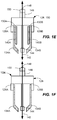
- the gripper apparatus 104 may, in one aspect, be adapted and operable to simultaneously grasp a sample container 106 by both the sample tube body 106A and the cap 106B. In this manner, excellent gripping action of the sample container 106 is provided, even when the sample tube body 106A and/or cap 106B may be quite variable in size from one sample container 106 to the next.
- first and second gripper components 128, 130 may be arranged in a side-by-side configuration as shown in the FIG. 1D embodiment.
- the side-by-side configuration of the components 128, 130 is the same for the embodiment of FIG. 1A and 1E .
- the gripper components 128, 130 may be parallel jaw grippers, such a two-jaw model DPDL series parallel gripper available from De-Sta-Co of Charlevoix, Michigan.
- any suitable gripper component that includes moveable jaws may be used, such as parallel or even nonparallel moveable jaws.
- the gripper components 128, 130 may be electrically, pneumatically, or hydraulically driven to open and close the jaws.
- the invention may be adapted to chucking type, three-jaw gripper components.
- opposing jaws 128A, 128B of the first gripper component 128 may be actuated to move a first finger 134A and a second finger 134B (a first finger pair) that are mechanically coupled to the jaws 128A, 128B such that they open and close along the directions indicated by arrows 135.
- opposing jaws 130A, 130B of the second gripper component 130 may be mechanically coupled to third and fourth fingers 140A, 140B.
- the jaws 130A, 130B also be moveable to open and close along the directions indicated by arrows 137 to move (open and close) the third and fourth fingers 140A, 140B (a second finger pair) that are coupled to the jaws 130A, 130B.
- the first pair of fingers 134A, 134B may be adapted to contact and grip the sample tube body 106A (e.g., on an upper portion thereof below cap 106B), and the second pair of fingers 140A, 140B may be adapted to contact and grip the cap 106B (e.g., on the sides thereof).
- the fingers 134A, 134B and fingers 140A, 140B may be aligned along a gripper axis 142 and each pair may be positioned in an opposed orientation across the gripper axis 142.
- one pair of fingers may be recessed within another pair thereby enabling the gripping action to be provided along a same transverse direction (e.g., horizontal) in a relatively confined space. This may be required when one of the locations from which the sample containers 106 are transferred to and from is a sample rack 108 including many tightly spaced sample containers 106 (see Fig. 1B ). For example, as shown in the embodiment of FIG.
- a portion of fingers 140A, 140B may be received in recesses 143A, 143B formed in the fingers 134A, 134B.
- the second pair 140A, 140B adapted to grip the cap 106B are shorter in length that the first pair 134A, 134B.
- the gripper apparatus 104 may include only a single gripper component 128 including a first and second moveable jaws 128A, 128B wherein a first finger 134A is coupled to the first moveable jaw 128A, and a second finger 134B is coupled to the second moveable jaw 128B.
- the first and second fingers 134A, 134B are adapted to grip a sample container 106 (not shown) as in the aforementioned embodiments.
- a seating member 144 is provided and positioned adjacent to the first and second fingers 134A, 134B and is moveable (e.g., translatable) along the gripper axis 142.
- the seating member 144 may be any suitable member adapted and functioning to contact the cap 106A.
- the seating member 144 may be a cylindrically-shaped puck.
- the seating member 144 may simply be an end of a rod or shaft.
- the translation capability (extension and retraction) of the seating member 144 is provided by a shaft 148 being constrained in movement to a direction coincident with the gripper axis 142.
- the motion constraint may be provided by any suitable slide member, such as bearings (e.g., linear bearings) or bushings (not shown) engaging the shaft 148.
- Controlled linear motion of the seating member 144 along the gripper axis 142 is provided by any suitable linear motion-producer 149, such as a linear motor, linear servo motor, linear drive, drive motor and gear assembly, etc.
- a sensor 150 (or a plurality of sensors) may be provided to sense a position of the seating member 144 along the gripper axis 142 and provide position information to a suitable position controller 146 for determining a position of the seating member 144.
- the sensor 150 may be an LVDT, for example. Other sensors adapted to sense linear motion may be utilized. If gripping only the tube body 106A of the sample container 106 is sought together with excellent position control, the gripper apparatus 104 of FIG. 1E consisting of a single jaw pair and a seating member 144 may be inserted in place of the gripper apparatus 104 of FIG. 1A .
- a similar seating member 144, linear motion-producer 149, and sensor 150 as described above is also provided in the embodiments of FIGs. 1A and 1E , and FIGs. 1C and 1D .
- Each linear motion-producer 149 driving each seating member 144 is electrically coupled to a seating member position control 146 that is adapted to drive the seating member 144 to any preprogrammed extension or retraction position alongside the first and second fingers 134A, 134B.
- the seating member 144 is adapted to contact a cap 106B of the sample container 106 at various times during the transfer cycle of the sample container 106.
- the first and second fingers 134A, 134B are in an opened configuration, and the gripper apparatus 102 has been arranged to pick a sample container 106 at a first location (e.g., from a sample rack 108)
- the seating member 144 is fully or nearly fully extended.
- the seating member 144 is positioned towards the ends of the fingers 134A, 134B wherein the fingers 134A, 134B are shown in an opened configuration.
- this aspect of the invention only requires a single pair of fingers operative with the seating member 144.
- additional fingers e.g., fingers 140A, 140B
- the control of the motion of the fingers 134A, 134B and fingers 140A, 140B may be accomplished by first finger pair control 151 and by second finger pair control 153 that are coupled with the gripper components 128, 130, respectively.
- the coupling may be electrical when the gripper components 128, 130 are electrical.
- the coupling may be to a servo, pumping mechanism, or valve when the gripper components 128, 130, are hydraulic or pneumatic.
- the respective opening and closing of fingers 134A, 134B and 14A, 140B may be appropriately controlled via suitable control signals from finger pair controls 151, 153 according to a preprogrammed routine.
- the motion of the fingers 134A, 134B and 14A, 140B is preferably coordinated with the operation of the seating member 144.
- the sample container transfer system 100 may include a limiting device 155.
- the limiting device 155 may be a linear clutch, a crash slide, or other force or motion limiting device.
- the limiting device 155 may be mounted on or to the gripper apparatus 104 or elsewhere between the robot apparatus 102 and the gripper apparatus 104.
- the limiting device 155 may be mounted to a bracket 156 which attaches to the gripper apparatus 104.
- the limiting device 155 may receive a vertical shaft 158 of the robot apparatus 102.
- the limiting device 155 may function to detect collisions (via exceeding a preset load) and break away (e.g., along the Z-axis) by allowing shaft 158 to slide in the limiting device 155.
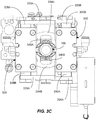
- FIGs. 2A-2C Another embodiment of a sample container transfer system 200 including a gripper apparatus 204 is shown in FIGs. 2A-2C .
- the sample container transfer system 200 includes a robot apparatus 202 and a gripper apparatus 204.
- the robot apparatus 202 includes a rotational motor 212 adapted to cause rotation of an arm assembly 214 which causes rotation of the gripper apparatus 204 about axis 216.
- Vertical motion of the gripper apparatus 204 may be provided by vertical motor 218 which cases shaft 218A to move vertically up (+Z) and down (-Z).
- the shaft 218A may be coupled to a bracket assembly 219, which in turn may be coupled to the gripper apparatus 204.
- the bracket assembly 219 may include a limiting device 221 such as a linear clutch apparatus that functions to limit a load that may be applied to the gripper apparatus 204 in the vertical direction (+Z) along the Z axis.
- the limiting device 221 may include a clutch portion 221A which slips upon encountering a designed pre-established force level.
- the clutch portion 221A may frictionally engage a clutch shaft or shafts (see FIG. 2C ) 221B and relative motion between the clutch portion 221A and the clutch shaft(s) 221B may occur when the predefined load is exceeded.
- Anti-rotation of the clutch shaft 221B relative to the clutch portion 221A may be provided, such as by a key and keyway, use of more than one shaft, or other suitable mechanism.
- dual moveable-jaw gripper components 228, 230 are provided. These components 228, 230 may be mounted on and coupled to a bracket 231. Movement of the gripper components 228, 230 causes motion (opening and closing) of the finger pairs 234, 240.
- connector brackets 233A, 233B and 235A, 235B connect between the jaws 228A, 228B, 230A, 230B of the gripper components 228, 230 and the finger pairs 234, 240.
- One or more springs 237 may connect between the respective brackets (e.g., 233A, 233B and 235A, 235B) to ensure safe failure of the gripper component 228 to a closed condition.
- the spring 237 is shown unconnected in FIG. 2C .
- the lower finger pair 234 is adapted to grip the tube body 106 of the sample container 206, whereas the upper pair 240 is adapted to grip the cap 206B.
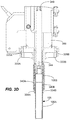
- a seating assembly 241 is also coupled and mounted to the bracket 231.
- the seating assembly 241 functions to cause the vertical motion of the seating member 244.
- the seating assembly 241 includes a vertical motor 249 adapted to cause the motion of the seating member 244, the seating member 244, and sensors.
- Various sensors 250A, 250B may be provided for providing feedback information about a location of the seating member 244. For example, end switches may be used. Other types of position sensors may be used.
- the gripper apparatus 304 includes first and second gripper components 328, 330 each having moveable jaws 328A, 328B, 330A, 330B, first and second fingers 334A, 334B coupled to the moveable jaws 328A, 328B via plate-like connector brackets 333A, 333B; second and third fingers 340A, 340B coupled to the moveable jaws 330A, 330B via the plate-like connector brackets 335A, 335B; seating member 344, shaft 348, linear motion-producer 349, limiting device 355, and bracket 356.
- one or more of the fingers 340A, 340B may include serrations along their gripping surfaces to aid in gripping the cap 106B.
- the seating member 344 is provided as an end of a rod that connects to the shaft 348.
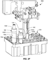
- Fig. 3F illustrates the gripper apparatus 304 located at a first location.
- Several sample containers 106 are received in the sample rack 308 and are illustrated having different heights of the sample tube body 106A and different configurations of caps 106B.
- the present invention is adept at picking such sample containers 106 having different shapes and configurations from a sample rack 308 and then placing these picked sample containers 106 at a second location.
- the pick operation may actually transfer the sample rack from a first location to a second location.
- FIG. 3F illustrates performing a sample rack pick operation at a first location. On this sample rack, a central post 360 that mimics a tube and cap configuration extends from a body of the sample rack 308.
- the central post 360 includes one or more side extenders 360A that extend laterally from the post body and are adapted to register on one or more sides of the finger pair 334A, 334B. Notches may be formed on one or more sides of the fingers 334A, 334B, and the notches having an approximate shape of the portion of the side extender 360A that it is engaged with to further aid with registration.
- the side extenders 360A help keep the sample rack 308 rotationally aligned so that the place operation of the sample rack 308 may be precisely carried out with the orientation of the sample rack 308 relative to the gripper apparatus 304 being known.
- FIG. 3G illustrates an operation by the gripper apparatus and robot apparatus (not shown in FIG. 3G ) where the sample container 106 including sample tube body 106A and cap 106B are inserted into a receptacle 110 (shown cross sectioned) as part of a place operation.
- the receptacle 310 may receive the sample container 106 and be used to carry the container to various pre-processing operations or to a clinical analyzer for testing.
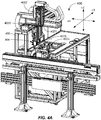
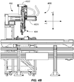
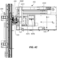
- the robot apparatus 402 is a multistage robot apparatus including a linear x-axis stage 402X, a linear Y-axis stage 402Y, and a linear Z axis stage 402Z for carrying out X-axis, Y-axis, and Z-axis motions of the gripper apparatus 404 thereby allowing the three-axis motion of a sample container (e.g., 106) gripped by the gripper apparatus 404.
- the gripper apparatus 404 may be any of the aforementioned gripper apparatus types as shown and described with reference to FIGs. 1A-1E , FIGs. 2A-2C , and FIGs. 3A-3G , for example.
- the robot apparatus 404 may be mounted on any suitable frame 405.
- the frame 405 may include one or more trays 407A, 407B mounted thereon at various fixed locations.
- the trays may receive one or more sample racks 408 in fixed locations thereof.
- the locations of the sample racks 408 may be fixed by pins projecting from the trays 407A, 407B and the pins may be received in bores or slots (not shown) formed in the bottom of the sample racks 408.
- Multiple sample containers e.g., 10 ⁇
- Sample racks 408 may be the same as is shown in FIG. 3F , for example.
- a suitable position controller may cause the robot apparatus 402 to move the gripper apparatus 404 in one or more of the X, Y and Z directions and preferably in all three.
- the gripper apparatus 404 may pick a sample container (e.g., 106) from a rack 408 and transfer the sample container to a clinical analyzer or other pre-processing equipment.
- the sample container e.g., 106
- the sample container is inserted into a receptacle of a centrifuge apparatus 409 that may carry out a preliminary step of centrifugation of one or more specimens contained in one or more sample containers.
- the current sample container transfer apparatus 400 may be used to feed sample containers (e.g., 106) to and from any type of analyzer or piece of equipment that processes sample containers and for which a high level of automation is sought. After completion of processing of all of the sample containers within the sample rack 408, the rack 408 itself, and the included sample containers may be placed on a conveyor destined for a next processing operation, such as another clinical analyzer or another pre-processing station.
- sample containers e.g., 106
- the rack 408 itself, and the included sample containers may be placed on a conveyor destined for a next processing operation, such as another clinical analyzer or another pre-processing station.
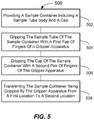
- the method 500 includes the steps of providing a sample container 106 including a sample tube body 106A and a cap 106B in 502.
- the sample container 106 is gripped by the sample tube 106A by a first pair of fingers (e.g., fingers 134A, 134B).
- the sample container 106 is gripped by the cap 106B by a second pair of fingers (e.g., fingers 140A, 140B). In this way, excellent gripping and position control of the sample container 106 may be accomplished.
- the sample container 106 may be transferred from a first location to a second location by the gripper apparatus (e.g., 104) via control of the robot apparatus (e.g., 102) by robot position control subsystem 122.
- the sample container 106 may be transferred from a sample rack 108 (see FIG. 1B ) to a receptacle 110(see FIG. 1A ) and then inserted in the receptacle 110.
- the method 600 includes the steps of providing a sample container 106 including a sample tube body 106A and a cap 106B in 502.
- a gripper component e.g., 128 is provided that includes a first moveable jaw (e.g., 128A) and a second moveable jaw (e.g., 128B) each arranged alongside of a gripper axis (e.g., 142).
- a first finger e.g., 134A
- a second finger e.g., 134B
- the cap 106B of the sample container 106 is contacted with a seating member (e.g., 144).
- the seating member is moveable along the gripper axis (e.g., 142), and is positioned adjacent to the first and second fingers.
- the cap 106B is contacted when the first and second fingers are in an opened configuration.
- the sample container 106 is gripped by the sample tube 106A by the first pair of fingers (e.g., fingers 134A, 134B), and simultaneously gripped by the cap 106B by a second pair of fingers (e.g., fingers 140A, 140B). Following the gripping, the sample container 106 is transferred from a first location to a second location by the gripper apparatus (e.g., 104) via control of the robot apparatus (e.g., 102).
- the gripper apparatus e.g., 104
- the robot apparatus e.g. 102
- the robot apparatus e.g., 102 and gripper apparatus (e.g., 104) perform a place operation wherein the sample container 106 is first inserted into a receptacle (e.g., 110) to a first depth position within the receptacle, and then the seating member (e.g., 144) contacts the cap 106B of the sample container 106 to move the sample container 106 to a second deeper position within the receptacle 110.
- a receptacle e.g., 110
- the seating member e.g., 144
- the robot apparatus e.g., 102 and gripper apparatus (e.g., 104) may perform a pick operation wherein the cap 106B of the sample container 106 is first contacted with the seating member (e.g., 144) in an extended configuration prior to gripping of both of the sample tube body 106A and the cap 106B of the sample container 106 by the first finger pair (e.g. 134A, 134B) and the separate second finger pair (e.g., 140A, 140B).
- the first finger pair e.g. 134A, 134B
- the separate second finger pair e.g. 140A, 140B
Landscapes
- Analytical Chemistry (AREA)
- Immunology (AREA)
- Physics & Mathematics (AREA)
- Health & Medical Sciences (AREA)
- Life Sciences & Earth Sciences (AREA)
- Chemical & Material Sciences (AREA)
- General Health & Medical Sciences (AREA)
- Biochemistry (AREA)
- Robotics (AREA)
- General Physics & Mathematics (AREA)
- Engineering & Computer Science (AREA)
- Pathology (AREA)
- Manipulator (AREA)
- Automatic Analysis And Handling Materials Therefor (AREA)
Claims (12)
- Greifervorrichtung (104), Folgendes umfassend:eine Greiferkomponente (128), die eine erste und eine zweite bewegliche Backe (128A, 128B) aufweist, die entlang einer Greiferachse (142) angeordnet sind;ein erstes Paar entgegengesetzter Finger (134A, 134B), die in einer entgegengesetzten Ausrichtung um die Greiferachse positioniert sind und Folgendes aufweisen:einen ersten Finger (134A), der mit der ersten beweglichen Backe (128A) gekoppelt ist;und einen zweiten Finger (134B), der mit der zweiten beweglichen Backe (128B) gekoppelt ist, wobei der erste und zweite Finger dazu angepasst sind, einen Probenbehälter (106) zu greifen, wobei der Probenbehälter einen Röhrchenkörper (106A) und einen Deckel (106B) aufweist; undein Setzelement (144), das an den ersten und zweiten Finger angrenzend positioniert und entlang der Greiferachse beweglich ist, wobei das Setzelement dazu angepasst ist, den Deckel des Probenbehälters zu berühren, wenn der erste und zweite Finger in einer geöffneten Konfiguration sind;dadurch gekennzeichnet, dass die Greifervorrichtung ferner Folgendes umfasst:einen Linearbewegungserzeuger (149), der mit dem Setzelement gekoppelt und dazu ausgelegt ist, eine gesteuerte Linearbewegung bereitzustellen, um das Setzelement entlang der Greiferachse zu verfahren; undeine Setzelementpositionssteuerung (146), die mit dem Linearbewegungserzeuger elektrisch gekoppelt und dazu angepasst ist, das Setzelement in eine beliebige, voreingestellte Ausfahr- oder Einfahrposition entlang des ersten und zweiten Fingers zu verfahren.
- Greifervorrichtung nach Anspruch 1, wobei der erste und zweite Finger in einer entgegengesetzten Ausrichtung um die Greiferachse positioniert sind.
- Greifervorrichtung nach Anspruch 2, ferner ein zweites Paar Finger, das einen dritten Finger und einen vierten Finger aufweist, umfassend, wobei der dritte und vierte Finger in einer entgegengesetzten Ausrichtung um die Greiferachse positioniert und dazu angepasst sind, den Probenbehälter zu greifen.
- Greifervorrichtung nach Anspruch 3, ferner Folgendes umfassend:eine zweite Greiferkomponente, die eine dritte bewegliche Backe und eine vierte bewegliche Backe aufweist;einen dritten Finger, der mit der dritten beweglichen Backe gekoppelt ist;einen vierten Finger, der mit der vierten beweglichen Backe gekoppelt ist;wobei der erste und zweite Finger jeweils entlang der Greiferachse angeordnet und dazu angepasst sind, einen Probenröhrchenkörper des Probenbehälters zu greifen; undwobei der dritte und vierte Finger jeweils entlang der Greiferachse angeordnet und dazu angepasst sind, einen Deckel eines Probenbehälters zu greifen.
- Greifervorrichtung nach Anspruch 4, wobei das zweite Paar Finger kürzer als das erste Paar Finger ist und das zweite Paar Finger dazu angepasst ist, den Deckel zu greifen.
- Greifervorrichtung nach Anspruch 4, ferner einen Abschnitt jedes des zweiten Paars Finger umfassend, die in im ersten Paar entgegengesetzter Finger ausgebildeten Aussparungen aufgenommen sind.
- Probenbehältertransportsystem, Folgendes umfassend:eine Robotervorrichtung, die in mindestens eine Koordinatenrichtung beweglich ist; undeine Greifervorrichtung, die mit der Robotervorrichtung gekoppelt ist und davon bewegt werden kann, wobei die Greifervorrichtung eine Greifervorrichtung nach Anspruch 1 ist, die Folgendes aufweist:eine Greiferkomponente, die eine erste bewegliche Backe und eine zweite bewegliche Backe aufweist, die jeweils entlang einer Greiferachse angeordnet sind,einen ersten Finger, der mit der ersten beweglichen Backe gekoppelt ist,einen zweiten Finger, der mit der zweiten beweglichen Backe gekoppelt ist, wobei der erste und zweite Finger dazu angepasst sind, einen Probenbehälter zu greifen;ein Setzelement, das an den ersten und zweiten Finger angrenzend positioniert und entlang der Greiferachse beweglich ist, wobei das Setzelement dazu angepasst ist, den Deckel des Probenbehälters zu berühren, wenn der erste und zweite Finger in einer geöffneten Konfiguration sind;einen Linearbewegungserzeuger, der mit dem Setzelement gekoppelt und dazu ausgelegt ist, eine gesteuerte Linearbewegung bereitzustellen, um das Setzelement entlang der Greiferachse zu verfahren; undeine Setzelementpositionssteuerung, die mit dem Linearbewegungserzeuger elektrisch gekoppelt und dazu angepasst ist, das Setzelement in eine beliebige, voreingestellte Ausfahr- oder Einfahrposition entlang des ersten und zweiten Fingers zu verfahren.
- System nach Anspruch 7, ferner eine Lastbegrenzungseinrichtung umfassend, die zwischen die Robotervorrichtung und die Greifervorrichtung gekoppelt ist, wobei die Lastbegrenzungseinrichtung dazu angepasst ist, eine Last zu begrenzen, die während einer Transportoperation auf die Greifervorrichtung ausgeübt wird.
- System nach Anspruch 7, ferner Folgendes umfassend:eine zweite Greiferkomponente, die eine dritte bewegliche Backe und eine vierte bewegliche Backe aufweist, die entlang der Greiferachse angeordnet sind,wobei der erste Finger und der zweite Finger dazu angepasst sind, einen Probenröhrchenkörper eines Probenbehälters zu greifen,einen dritten Finger, der mit der dritten beweglichen Backe gekoppelt ist, undeinen vierten Finger, der mit der vierten beweglichen Backe gekoppelt ist,wobei der dritte Finger und der vierte Finger dazu angepasst sind, einen Deckel eines Probenbehälters zu greifen.
- Verfahren zum Transportieren eines Probenbehälters, Folgendes umfassend:Bereitstellen einer Greifervorrichtung nach Anspruch 1, die eine Greiferkomponente umfasst, die eine erste bewegliche Backe und eine zweite bewegliche Backe aufweist, die jeweils entlang einer Greiferachse angeordnet sind;Bereitstellen eines ersten Fingers, der mit der ersten beweglichen Backe gekoppelt ist;Bereitstellen eines zweiten Fingers, der mit der zweiten beweglichen Backe gekoppelt ist;Berühren eines Deckels des Probenbehälters mit einem Setzelement, das entlang der Greiferachse beweglich ist und an den ersten und zweiten Finger angrenzend positioniert ist, wenn der erste und zweite Finger in einer geöffneten Konfiguration sind; undGreifen des Probenbehälters mit dem ersten Finger und dem zweiten Finger;dadurch gekennzeichnet, dass das Verfahren zum Transportieren eines Probenbehälters ferner Folgendes umfasst:
Durchführen einer Platzierungsoperation, wobei der Probenbehälter zunächst unter Verwendung der Greiferkomponente in eine Aufnahme in einer ersten Tiefenposition innerhalb der Aufnahme eingesetzt wird und anschließend das von einem Linearbewegungserzeuger angetriebene Setzelement den Deckel des Probenbehälters berührt, um den Probenbehälter in eine zweite, tiefere Position innerhalb der Aufnahme zu bewegen. - Verfahren nach Anspruch 10, ferner Folgendes umfassend:
Durchführen einer Auswahloperation, wobei der Deckel des Probenbehälters zunächst mit dem Setzelement in einer ausgefahrenen Konfiguration berührt wird, bevor sowohl das Probenröhrchen als auch der Deckel des Probenbehälters gegriffen werden. - Verfahren nach Anspruch 10, ferner Folgendes umfassend:Greifen eines Probenröhrchenkörpers des Probenbehälters mit einem ersten Paar Finger einer Greifervorrichtung;Greifen des Deckels des Probenbehälters mit einem zweiten Paar Finger der Greifervorrichtung; undTransportieren des von der Greifervorrichtung gegriffenen Probenbehälters von einer ersten Position zu einer zweiten Position,wobei die Greifervorrichtung mit einer Robotervorrichtung gekoppelt ist und davon bewegt werden kann.
Applications Claiming Priority (2)
| Application Number | Priority Date | Filing Date | Title |
|---|---|---|---|
| US23202109P | 2009-08-07 | 2009-08-07 | |
| PCT/US2010/044648 WO2011017586A1 (en) | 2009-08-07 | 2010-08-06 | Methods, systems, and apparatus adapted to transfer sample containers |
Publications (3)
| Publication Number | Publication Date |
|---|---|
| EP2462455A1 EP2462455A1 (de) | 2012-06-13 |
| EP2462455A4 EP2462455A4 (de) | 2018-01-10 |
| EP2462455B1 true EP2462455B1 (de) | 2019-09-25 |
Family
ID=43544677
Family Applications (1)
| Application Number | Title | Priority Date | Filing Date |
|---|---|---|---|
| EP10807206.7A Active EP2462455B1 (de) | 2009-08-07 | 2010-08-06 | Verfahren, systeme und vorrichtung zum transport von probenbehältern |
Country Status (5)
| Country | Link |
|---|---|
| US (1) | US9164113B2 (de) |
| EP (1) | EP2462455B1 (de) |
| JP (1) | JP2013501633A (de) |
| CN (1) | CN102576032A (de) |
| WO (1) | WO2011017586A1 (de) |
Families Citing this family (34)
| Publication number | Priority date | Publication date | Assignee | Title |
|---|---|---|---|---|
| EP2190566B1 (de) * | 2007-08-28 | 2012-10-03 | Corbett Research Pty Ltd | Vorrichtung zur durchführung von temperaturzyklen mit einem probeneinlass, der gezielt geöffnet werden kann |
| DE102011083794A1 (de) * | 2011-09-29 | 2013-04-04 | Hamilton Bonaduz Ag | Greifvorrichtung für Probenbehälter |
| DE102011055899B4 (de) * | 2011-11-30 | 2013-11-21 | Andreas Hettich Gmbh & Co. Kg | Verfahren und eine Vorrichtung zum Handhaben von Probenbehältern |
| JP5936384B2 (ja) * | 2012-02-14 | 2016-06-22 | 株式会社椿本チエイン | ピッキング装置 |
| CN203236382U (zh) * | 2012-12-17 | 2013-10-16 | 鸿准精密模具(昆山)有限公司 | 夹持装置 |
| JP6101091B2 (ja) * | 2013-01-29 | 2017-03-22 | 株式会社日立ハイテクノロジーズ | 検体容器移動システムおよび検体容器移動方法 |
| JP6336715B2 (ja) * | 2013-05-30 | 2018-06-06 | 富士レビオ株式会社 | 把持機構 |
| US9778275B2 (en) * | 2013-11-06 | 2017-10-03 | Siemens Healthcare Diagnostics Inc. | Confirmed placement of sample tubes in a servo driven automation system using trajectory deviation |
| JP6419540B2 (ja) * | 2014-11-14 | 2018-11-07 | シスメックス株式会社 | 検体測定装置および検体測定方法 |
| WO2017072414A1 (en) | 2015-10-30 | 2017-05-04 | Thermo Fisher Scientific Oy | Gripper finger and gripper |
| EP3196655B1 (de) | 2016-01-22 | 2020-11-25 | Roche Diagniostics GmbH | Vorrichtung zur handhabung eines laborprobenbehälterträgers und laborsystem |
| EP3196654B1 (de) | 2016-01-22 | 2023-06-21 | Roche Diagnostics GmbH | Verfahren und vorrichtung zur übertragung von probenröhrchen zwischen einem laborautomatisierungssystem und einem probenarchivierungssystem |
| EP3196648B1 (de) * | 2016-01-22 | 2021-03-31 | Roche Diagniostics GmbH | Vorrichtung zum heben einer probenröhre |
| EP3236267B1 (de) * | 2016-04-18 | 2021-09-08 | Roche Diagnostics GmbH | Entstopfer und vorrichtung |
| GB2551991A (en) * | 2016-07-04 | 2018-01-10 | Stratec Biomedical Ag | Device for handling vials |
| US11065760B2 (en) * | 2016-08-09 | 2021-07-20 | Inventec Appliances (Pudong) Corporation | Multiaxial robot with cover |
| DE102017101290B4 (de) * | 2017-01-24 | 2022-01-20 | Dr. Ing. H.C. F. Porsche Aktiengesellschaft | Vorrichtung zur Bewegung eines Werkstücks |
| EP3367102A1 (de) * | 2017-02-23 | 2018-08-29 | Roche Diagnostics GmbH | Greifvorrichtung probenbehälterverarbeitungssystem |
| EP3388839B1 (de) * | 2017-04-10 | 2023-08-30 | F. Hoffmann-La Roche AG | Zentriereinheit für ein transportfach für labordiagnostika |
| JP7119084B2 (ja) * | 2017-11-30 | 2022-08-16 | ライカ バイオシステムズ イメージング インコーポレイテッド | スライドラックグリッパ装置 |
| JP7002326B2 (ja) * | 2017-12-26 | 2022-01-20 | 川崎重工業株式会社 | 蓋閉じ装置及び蓋閉じ方法 |
| CN108839043A (zh) * | 2018-06-05 | 2018-11-20 | 东莞市天合机电开发有限公司 | 一种带布卷辊拾取机械手 |
| CN109061211B (zh) * | 2018-10-29 | 2025-02-18 | 苏州新波生物技术有限公司 | 一种用于拾取和放置反应杯的装置和方法以及含有该装置的设备 |
| JP2020159872A (ja) * | 2019-03-27 | 2020-10-01 | 株式会社リガク | 試料容器押圧機構、試料搬送装置、分析装置および試料搬送方法 |
| WO2021216931A1 (en) * | 2020-04-23 | 2021-10-28 | Gen-Probe Incorporated | Gripper apparatus with reduced contamination risk |
| US20230236213A1 (en) * | 2020-06-05 | 2023-07-27 | Shimadzu Corporation | Automatic sample injection device |
| EP3925737A1 (de) * | 2020-06-16 | 2021-12-22 | Roche Diagnostics GmbH | Greifsystem und laborautomatisierungssystem |
| CN112248012B (zh) * | 2020-10-15 | 2023-08-18 | 山东津晨佳金属制品有限公司 | 方便钢管搬运稳定的工程机械手 |
| CN116568402A (zh) * | 2020-12-07 | 2023-08-08 | 柏业公司 | 导电性移液管安装用适配器、样品管开闭装置及样品自动分析系统 |
| EP4043887B1 (de) * | 2021-02-15 | 2023-11-15 | Roche Diagnostics GmbH | Kappenabnehmer zum entfernen einer kappe von einem laborprobenbehälter |
| GB202109974D0 (en) * | 2021-07-09 | 2021-08-25 | Randox Laboratories Ltd | Sample extractor |
| US11542103B1 (en) * | 2021-07-29 | 2023-01-03 | Rios Intelligent Machines, Inc. | Food-grade robotic gripper for automated production work cell |
| CN113820506A (zh) * | 2021-08-10 | 2021-12-21 | 西安金域医学检验所有限公司 | 一种自动排号仪 |
| CN120195417A (zh) * | 2023-12-21 | 2025-06-24 | 贝克曼库尔特实验系统(苏州)有限公司 | 容器操纵装置和包括该容器操纵装置的医用检测分析仪 |
Citations (1)
| Publication number | Priority date | Publication date | Assignee | Title |
|---|---|---|---|---|
| ES2226591A1 (es) * | 2004-11-23 | 2005-03-16 | Alt3 Enginyers, S.L. | Maquina para la extraccion automatica de tapones de recipientes. |
Family Cites Families (13)
| Publication number | Priority date | Publication date | Assignee | Title |
|---|---|---|---|---|
| US4522089A (en) * | 1983-10-28 | 1985-06-11 | Alvi Javid R | Test tube cap remover |
| JPS61230894A (ja) * | 1985-04-05 | 1986-10-15 | 三菱電機株式会社 | 産業用ロボツトのハンド装置 |
| JPS6334029A (ja) * | 1986-07-23 | 1988-02-13 | Matsushita Electric Ind Co Ltd | 部品の挾持装置 |
| JP2674908B2 (ja) * | 1991-09-06 | 1997-11-12 | 株式会社クボタ | 管接合装置 |
| JP3347407B2 (ja) * | 1993-08-17 | 2002-11-20 | シスメックス株式会社 | 試料容器回転装置 |
| JP3251441B2 (ja) * | 1994-09-30 | 2002-01-28 | シスメックス株式会社 | キュベットおよびキュベット搬送装置 |
| JPH08243969A (ja) * | 1995-03-13 | 1996-09-24 | Toyota Motor Corp | 部品把持ハンド |
| US6586255B1 (en) * | 1997-07-21 | 2003-07-01 | Quest Diagnostics Incorporated | Automated centrifuge loading device |
| IT1314856B1 (it) * | 2000-07-06 | 2003-01-16 | Tecnorama Srl | Apparecchiatura per la preparazione automatizzata di soluzioni ed unsistema combinato per il dosaggio di prodotti liquidi, prodotti solidi |
| US7128874B2 (en) | 2001-01-26 | 2006-10-31 | Beckman Coulter, Inc. | Method and system for picking and placing vessels |
| JP3880586B2 (ja) * | 2004-03-26 | 2007-02-14 | 株式会社アイディエス | 試験管栓取外し装置 |
| JP4098272B2 (ja) * | 2004-04-26 | 2008-06-11 | 株式会社アイディエス | 試験管のバーコード読取り装置 |
| JP2009006460A (ja) | 2007-06-29 | 2009-01-15 | Mitsubishi Electric Corp | ロボットハンド |
-
2010
- 2010-08-06 US US13/389,320 patent/US9164113B2/en active Active
- 2010-08-06 EP EP10807206.7A patent/EP2462455B1/de active Active
- 2010-08-06 WO PCT/US2010/044648 patent/WO2011017586A1/en not_active Ceased
- 2010-08-06 JP JP2012523970A patent/JP2013501633A/ja active Pending
- 2010-08-06 CN CN2010800447937A patent/CN102576032A/zh active Pending
Patent Citations (1)
| Publication number | Priority date | Publication date | Assignee | Title |
|---|---|---|---|---|
| ES2226591A1 (es) * | 2004-11-23 | 2005-03-16 | Alt3 Enginyers, S.L. | Maquina para la extraccion automatica de tapones de recipientes. |
Also Published As
| Publication number | Publication date |
|---|---|
| US9164113B2 (en) | 2015-10-20 |
| CN102576032A (zh) | 2012-07-11 |
| EP2462455A4 (de) | 2018-01-10 |
| JP2013501633A (ja) | 2013-01-17 |
| EP2462455A1 (de) | 2012-06-13 |
| WO2011017586A1 (en) | 2011-02-10 |
| US20120134769A1 (en) | 2012-05-31 |
Similar Documents
| Publication | Publication Date | Title |
|---|---|---|
| EP2462455B1 (de) | Verfahren, systeme und vorrichtung zum transport von probenbehältern | |
| US9335337B2 (en) | Apparatus for gripping and holding diagnostic cassettes | |
| EP2613156B1 (de) | Probenübertragungsmechanismus | |
| EP1355766B1 (de) | Verfahren und vorrichtung zum aufnehmen und abstellen von behältern | |
| US6592324B2 (en) | Gripper mechanism | |
| US9085413B2 (en) | Methods and systems adapted to handle sticky sample containers | |
| EP3798639B1 (de) | Greifer und verfahren zur automatisierten handhabung von probenröhrchen | |
| JP2017129576A (ja) | 試料管を持ち上げるためのデバイス | |
| WO2007149628A9 (en) | Robotic gripper for transporting multiple object types | |
| JP2023510946A (ja) | 実験器具位置合わせシステム及びリキッドハンドリングシステム、並びにこれらを含む方法 | |
| CN112060067A (zh) | 一种自动化生物样本处理的机械臂装置 | |
| CN219972291U (zh) | 样本前处理系统 | |
| CN117085758A (zh) | 用于夹持样品容器的夹持装置 | |
| CN116396850A (zh) | 一种全自动核酸样品处理系统 | |
| CN212402670U (zh) | 一种用于生物样本三维可调的移送设备 | |
| HK1170302A (en) | Methods, systems, and apparatus adapted to transfer sample containers | |
| CN217436865U (zh) | 用于释放或锁住工作台的结构和转运分离装置 | |
| EP4686946A1 (de) | System und verfahren zur handhabung von laborröhren | |
| EP4538714A1 (de) | Robotisches probenhandhabungssystem | |
| CN120275654A (zh) | 一种样本集中式前处理设备及方法 | |
| CN121131078A (zh) | 一种样品静置离心系统 | |
| WO2026048224A1 (ja) | モータシステムおよび把持装置 |
Legal Events
| Date | Code | Title | Description |
|---|---|---|---|
| PUAI | Public reference made under article 153(3) epc to a published international application that has entered the european phase |
Free format text: ORIGINAL CODE: 0009012 |
|
| 17P | Request for examination filed |
Effective date: 20120202 |
|
| AK | Designated contracting states |
Kind code of ref document: A1 Designated state(s): AL AT BE BG CH CY CZ DE DK EE ES FI FR GB GR HR HU IE IS IT LI LT LU LV MC MK MT NL NO PL PT RO SE SI SK SM TR |
|
| DAX | Request for extension of the european patent (deleted) | ||
| RA4 | Supplementary search report drawn up and despatched (corrected) |
Effective date: 20171208 |
|
| RIC1 | Information provided on ipc code assigned before grant |
Ipc: G01N 35/10 20060101AFI20171204BHEP |
|
| STAA | Information on the status of an ep patent application or granted ep patent |
Free format text: STATUS: EXAMINATION IS IN PROGRESS |
|
| 17Q | First examination report despatched |
Effective date: 20180921 |
|
| REG | Reference to a national code |
Ref country code: DE Ref legal event code: R079 Ref document number: 602010061244 Country of ref document: DE Free format text: PREVIOUS MAIN CLASS: G01N0035100000 Ipc: G01N0035000000 |
|
| GRAP | Despatch of communication of intention to grant a patent |
Free format text: ORIGINAL CODE: EPIDOSNIGR1 |
|
| STAA | Information on the status of an ep patent application or granted ep patent |
Free format text: STATUS: GRANT OF PATENT IS INTENDED |
|
| RIC1 | Information provided on ipc code assigned before grant |
Ipc: B25J 15/02 20060101ALN20190129BHEP Ipc: G01N 35/00 20060101AFI20190129BHEP Ipc: B25J 9/04 20060101ALN20190129BHEP Ipc: G01N 35/04 20060101ALN20190129BHEP |
|
| INTG | Intention to grant announced |
Effective date: 20190211 |
|
| GRAS | Grant fee paid |
Free format text: ORIGINAL CODE: EPIDOSNIGR3 |
|
| GRAA | (expected) grant |
Free format text: ORIGINAL CODE: 0009210 |
|
| STAA | Information on the status of an ep patent application or granted ep patent |
Free format text: STATUS: THE PATENT HAS BEEN GRANTED |
|
| AK | Designated contracting states |
Kind code of ref document: B1 Designated state(s): AL AT BE BG CH CY CZ DE DK EE ES FI FR GB GR HR HU IE IS IT LI LT LU LV MC MK MT NL NO PL PT RO SE SI SK SM TR |
|
| REG | Reference to a national code |
Ref country code: GB Ref legal event code: FG4D |
|
| REG | Reference to a national code |
Ref country code: CH Ref legal event code: EP |
|
| REG | Reference to a national code |
Ref country code: AT Ref legal event code: REF Ref document number: 1184318 Country of ref document: AT Kind code of ref document: T Effective date: 20191015 |
|
| REG | Reference to a national code |
Ref country code: IE Ref legal event code: FG4D |
|
| REG | Reference to a national code |
Ref country code: DE Ref legal event code: R096 Ref document number: 602010061244 Country of ref document: DE |
|
| REG | Reference to a national code |
Ref country code: NL Ref legal event code: MP Effective date: 20190925 |
|
| PG25 | Lapsed in a contracting state [announced via postgrant information from national office to epo] |
Ref country code: FI Free format text: LAPSE BECAUSE OF FAILURE TO SUBMIT A TRANSLATION OF THE DESCRIPTION OR TO PAY THE FEE WITHIN THE PRESCRIBED TIME-LIMIT Effective date: 20190925 Ref country code: NO Free format text: LAPSE BECAUSE OF FAILURE TO SUBMIT A TRANSLATION OF THE DESCRIPTION OR TO PAY THE FEE WITHIN THE PRESCRIBED TIME-LIMIT Effective date: 20191225 Ref country code: BG Free format text: LAPSE BECAUSE OF FAILURE TO SUBMIT A TRANSLATION OF THE DESCRIPTION OR TO PAY THE FEE WITHIN THE PRESCRIBED TIME-LIMIT Effective date: 20191225 Ref country code: SE Free format text: LAPSE BECAUSE OF FAILURE TO SUBMIT A TRANSLATION OF THE DESCRIPTION OR TO PAY THE FEE WITHIN THE PRESCRIBED TIME-LIMIT Effective date: 20190925 Ref country code: LT Free format text: LAPSE BECAUSE OF FAILURE TO SUBMIT A TRANSLATION OF THE DESCRIPTION OR TO PAY THE FEE WITHIN THE PRESCRIBED TIME-LIMIT Effective date: 20190925 Ref country code: HR Free format text: LAPSE BECAUSE OF FAILURE TO SUBMIT A TRANSLATION OF THE DESCRIPTION OR TO PAY THE FEE WITHIN THE PRESCRIBED TIME-LIMIT Effective date: 20190925 |
|
| REG | Reference to a national code |
Ref country code: LT Ref legal event code: MG4D |
|
| PG25 | Lapsed in a contracting state [announced via postgrant information from national office to epo] |
Ref country code: GR Free format text: LAPSE BECAUSE OF FAILURE TO SUBMIT A TRANSLATION OF THE DESCRIPTION OR TO PAY THE FEE WITHIN THE PRESCRIBED TIME-LIMIT Effective date: 20191226 Ref country code: LV Free format text: LAPSE BECAUSE OF FAILURE TO SUBMIT A TRANSLATION OF THE DESCRIPTION OR TO PAY THE FEE WITHIN THE PRESCRIBED TIME-LIMIT Effective date: 20190925 |
|
| REG | Reference to a national code |
Ref country code: CH Ref legal event code: NV Representative=s name: SIEMENS SCHWEIZ AG, CH |
|
| REG | Reference to a national code |
Ref country code: AT Ref legal event code: MK05 Ref document number: 1184318 Country of ref document: AT Kind code of ref document: T Effective date: 20190925 |
|
| PG25 | Lapsed in a contracting state [announced via postgrant information from national office to epo] |
Ref country code: EE Free format text: LAPSE BECAUSE OF FAILURE TO SUBMIT A TRANSLATION OF THE DESCRIPTION OR TO PAY THE FEE WITHIN THE PRESCRIBED TIME-LIMIT Effective date: 20190925 Ref country code: PL Free format text: LAPSE BECAUSE OF FAILURE TO SUBMIT A TRANSLATION OF THE DESCRIPTION OR TO PAY THE FEE WITHIN THE PRESCRIBED TIME-LIMIT Effective date: 20190925 Ref country code: IT Free format text: LAPSE BECAUSE OF FAILURE TO SUBMIT A TRANSLATION OF THE DESCRIPTION OR TO PAY THE FEE WITHIN THE PRESCRIBED TIME-LIMIT Effective date: 20190925 Ref country code: AL Free format text: LAPSE BECAUSE OF FAILURE TO SUBMIT A TRANSLATION OF THE DESCRIPTION OR TO PAY THE FEE WITHIN THE PRESCRIBED TIME-LIMIT Effective date: 20190925 Ref country code: ES Free format text: LAPSE BECAUSE OF FAILURE TO SUBMIT A TRANSLATION OF THE DESCRIPTION OR TO PAY THE FEE WITHIN THE PRESCRIBED TIME-LIMIT Effective date: 20190925 Ref country code: PT Free format text: LAPSE BECAUSE OF FAILURE TO SUBMIT A TRANSLATION OF THE DESCRIPTION OR TO PAY THE FEE WITHIN THE PRESCRIBED TIME-LIMIT Effective date: 20200127 Ref country code: NL Free format text: LAPSE BECAUSE OF FAILURE TO SUBMIT A TRANSLATION OF THE DESCRIPTION OR TO PAY THE FEE WITHIN THE PRESCRIBED TIME-LIMIT Effective date: 20190925 Ref country code: AT Free format text: LAPSE BECAUSE OF FAILURE TO SUBMIT A TRANSLATION OF THE DESCRIPTION OR TO PAY THE FEE WITHIN THE PRESCRIBED TIME-LIMIT Effective date: 20190925 Ref country code: RO Free format text: LAPSE BECAUSE OF FAILURE TO SUBMIT A TRANSLATION OF THE DESCRIPTION OR TO PAY THE FEE WITHIN THE PRESCRIBED TIME-LIMIT Effective date: 20190925 |
|
| PG25 | Lapsed in a contracting state [announced via postgrant information from national office to epo] |
Ref country code: SK Free format text: LAPSE BECAUSE OF FAILURE TO SUBMIT A TRANSLATION OF THE DESCRIPTION OR TO PAY THE FEE WITHIN THE PRESCRIBED TIME-LIMIT Effective date: 20190925 Ref country code: CZ Free format text: LAPSE BECAUSE OF FAILURE TO SUBMIT A TRANSLATION OF THE DESCRIPTION OR TO PAY THE FEE WITHIN THE PRESCRIBED TIME-LIMIT Effective date: 20190925 Ref country code: IS Free format text: LAPSE BECAUSE OF FAILURE TO SUBMIT A TRANSLATION OF THE DESCRIPTION OR TO PAY THE FEE WITHIN THE PRESCRIBED TIME-LIMIT Effective date: 20200224 Ref country code: SM Free format text: LAPSE BECAUSE OF FAILURE TO SUBMIT A TRANSLATION OF THE DESCRIPTION OR TO PAY THE FEE WITHIN THE PRESCRIBED TIME-LIMIT Effective date: 20190925 |
|
| REG | Reference to a national code |
Ref country code: DE Ref legal event code: R097 Ref document number: 602010061244 Country of ref document: DE |
|
| PG2D | Information on lapse in contracting state deleted |
Ref country code: IS |
|
| PG25 | Lapsed in a contracting state [announced via postgrant information from national office to epo] |
Ref country code: DK Free format text: LAPSE BECAUSE OF FAILURE TO SUBMIT A TRANSLATION OF THE DESCRIPTION OR TO PAY THE FEE WITHIN THE PRESCRIBED TIME-LIMIT Effective date: 20190925 Ref country code: IS Free format text: LAPSE BECAUSE OF FAILURE TO SUBMIT A TRANSLATION OF THE DESCRIPTION OR TO PAY THE FEE WITHIN THE PRESCRIBED TIME-LIMIT Effective date: 20200126 |
|
| PLBE | No opposition filed within time limit |
Free format text: ORIGINAL CODE: 0009261 |
|
| STAA | Information on the status of an ep patent application or granted ep patent |
Free format text: STATUS: NO OPPOSITION FILED WITHIN TIME LIMIT |
|
| 26N | No opposition filed |
Effective date: 20200626 |
|
| PG25 | Lapsed in a contracting state [announced via postgrant information from national office to epo] |
Ref country code: SI Free format text: LAPSE BECAUSE OF FAILURE TO SUBMIT A TRANSLATION OF THE DESCRIPTION OR TO PAY THE FEE WITHIN THE PRESCRIBED TIME-LIMIT Effective date: 20190925 |
|
| PG25 | Lapsed in a contracting state [announced via postgrant information from national office to epo] |
Ref country code: MC Free format text: LAPSE BECAUSE OF FAILURE TO SUBMIT A TRANSLATION OF THE DESCRIPTION OR TO PAY THE FEE WITHIN THE PRESCRIBED TIME-LIMIT Effective date: 20190925 |
|
| REG | Reference to a national code |
Ref country code: CH Ref legal event code: PL |
|
| GBPC | Gb: european patent ceased through non-payment of renewal fee |
Effective date: 20200806 |
|
| PG25 | Lapsed in a contracting state [announced via postgrant information from national office to epo] |
Ref country code: CH Free format text: LAPSE BECAUSE OF NON-PAYMENT OF DUE FEES Effective date: 20200831 Ref country code: LI Free format text: LAPSE BECAUSE OF NON-PAYMENT OF DUE FEES Effective date: 20200831 Ref country code: LU Free format text: LAPSE BECAUSE OF NON-PAYMENT OF DUE FEES Effective date: 20200806 |
|
| REG | Reference to a national code |
Ref country code: BE Ref legal event code: MM Effective date: 20200831 |
|
| PG25 | Lapsed in a contracting state [announced via postgrant information from national office to epo] |
Ref country code: FR Free format text: LAPSE BECAUSE OF NON-PAYMENT OF DUE FEES Effective date: 20200831 |
|
| PG25 | Lapsed in a contracting state [announced via postgrant information from national office to epo] |
Ref country code: IE Free format text: LAPSE BECAUSE OF NON-PAYMENT OF DUE FEES Effective date: 20200806 Ref country code: GB Free format text: LAPSE BECAUSE OF NON-PAYMENT OF DUE FEES Effective date: 20200806 Ref country code: BE Free format text: LAPSE BECAUSE OF NON-PAYMENT OF DUE FEES Effective date: 20200831 |
|
| PG25 | Lapsed in a contracting state [announced via postgrant information from national office to epo] |
Ref country code: TR Free format text: LAPSE BECAUSE OF FAILURE TO SUBMIT A TRANSLATION OF THE DESCRIPTION OR TO PAY THE FEE WITHIN THE PRESCRIBED TIME-LIMIT Effective date: 20190925 Ref country code: MT Free format text: LAPSE BECAUSE OF FAILURE TO SUBMIT A TRANSLATION OF THE DESCRIPTION OR TO PAY THE FEE WITHIN THE PRESCRIBED TIME-LIMIT Effective date: 20190925 Ref country code: CY Free format text: LAPSE BECAUSE OF FAILURE TO SUBMIT A TRANSLATION OF THE DESCRIPTION OR TO PAY THE FEE WITHIN THE PRESCRIBED TIME-LIMIT Effective date: 20190925 |
|
| PG25 | Lapsed in a contracting state [announced via postgrant information from national office to epo] |
Ref country code: MK Free format text: LAPSE BECAUSE OF FAILURE TO SUBMIT A TRANSLATION OF THE DESCRIPTION OR TO PAY THE FEE WITHIN THE PRESCRIBED TIME-LIMIT Effective date: 20190925 |
|
| REG | Reference to a national code |
Ref country code: DE Ref legal event code: R082 Ref document number: 602010061244 Country of ref document: DE |
|
| PGFP | Annual fee paid to national office [announced via postgrant information from national office to epo] |
Ref country code: DE Payment date: 20251020 Year of fee payment: 16 |