EP2462894A2 - Procédé de fabrication de pièces dentaires - Google Patents
Procédé de fabrication de pièces dentaires Download PDFInfo
- Publication number
- EP2462894A2 EP2462894A2 EP20110401657 EP11401657A EP2462894A2 EP 2462894 A2 EP2462894 A2 EP 2462894A2 EP 20110401657 EP20110401657 EP 20110401657 EP 11401657 A EP11401657 A EP 11401657A EP 2462894 A2 EP2462894 A2 EP 2462894A2
- Authority
- EP
- European Patent Office
- Prior art keywords
- workpiece
- tool
- blank
- machining
- axis
- Prior art date
- Legal status (The legal status is an assumption and is not a legal conclusion. Google has not performed a legal analysis and makes no representation as to the accuracy of the status listed.)
- Granted
Links
Images





Classifications
-
- A—HUMAN NECESSITIES
- A61—MEDICAL OR VETERINARY SCIENCE; HYGIENE
- A61B—DIAGNOSIS; SURGERY; IDENTIFICATION
- A61B1/00—Instruments for performing medical examinations of the interior of cavities or tubes of the body by visual or photographical inspection, e.g. endoscopes; Illuminating arrangements therefor
- A61B1/00142—Instruments for performing medical examinations of the interior of cavities or tubes of the body by visual or photographical inspection, e.g. endoscopes; Illuminating arrangements therefor with means for preventing contamination, e.g. by using a sanitary sheath
-
- A—HUMAN NECESSITIES
- A61—MEDICAL OR VETERINARY SCIENCE; HYGIENE
- A61B—DIAGNOSIS; SURGERY; IDENTIFICATION
- A61B1/00—Instruments for performing medical examinations of the interior of cavities or tubes of the body by visual or photographical inspection, e.g. endoscopes; Illuminating arrangements therefor
- A61B1/313—Instruments for performing medical examinations of the interior of cavities or tubes of the body by visual or photographical inspection, e.g. endoscopes; Illuminating arrangements therefor for introducing through surgical openings, e.g. laparoscopes
- A61B1/3132—Instruments for performing medical examinations of the interior of cavities or tubes of the body by visual or photographical inspection, e.g. endoscopes; Illuminating arrangements therefor for introducing through surgical openings, e.g. laparoscopes for laparoscopy
-
- A—HUMAN NECESSITIES
- A61—MEDICAL OR VETERINARY SCIENCE; HYGIENE
- A61C—DENTISTRY; APPARATUS OR METHODS FOR ORAL OR DENTAL HYGIENE
- A61C13/00—Dental prostheses; Making same
- A61C13/0003—Making bridge-work, inlays, implants or the like
- A61C13/0006—Production methods
-
- A—HUMAN NECESSITIES
- A61—MEDICAL OR VETERINARY SCIENCE; HYGIENE
- A61C—DENTISTRY; APPARATUS OR METHODS FOR ORAL OR DENTAL HYGIENE
- A61C5/00—Filling or capping teeth
- A61C5/70—Tooth crowns; Making thereof
- A61C5/77—Methods or devices for making crowns
-
- A—HUMAN NECESSITIES
- A61—MEDICAL OR VETERINARY SCIENCE; HYGIENE
- A61C—DENTISTRY; APPARATUS OR METHODS FOR ORAL OR DENTAL HYGIENE
- A61C13/00—Dental prostheses; Making same
- A61C13/0003—Making bridge-work, inlays, implants or the like
- A61C13/0022—Blanks or green, unfinished dental restoration parts
Definitions
- the invention relates to a method for the material-removing machining of a particular flat blank for the production of dental workpieces, in particular of inlays, crowns, bridges, webs, Implantatsuprakonstrutationen, prostheses, models or the like, in which with a rotating tool alternately a crown inside of the workpiece in the Intrados position of the blank and a crown outside in the extrados position of the blank is processed, wherein the rotating tool, in particular a milling tool, drill or grinding tool both the front side and the shell side is brought into engagement with the workpiece, and wherein a uniform use of the entire cutting surface aspired and thus a coat-side engagement is preferred.
- the production of dental restorations is mainly done by material-removing machining-milling tools.
- a blank mainly blanks and blanks are used. These have nearly replaced the small single-tooth blanks (CEREC) with the exception of glass ceramics, lithium disilicate feldspar ceramics and infiltration ceramics.
- Porous zirconia ceramics, PMMA and composite plastics, dental waxes, cobalt-chromium steels and titanium alloys are the main materials used. These are mostly machined with double-edged carbide cutters in the form of hemisphere or edge-rounded cylinders. Mittler because four-cutting cutter planned.
- the tool which is arranged perpendicular to the surface of the blank, penetrates into the workpiece via the Z-axis infeed, while the material removal takes place via xy-axis feeds.
- layer by layer is removed by renewed Z-axis delivery, until the dental workpiece is exposed with holding webs on the one processing side (intrados side) (processing in xy planes).
- After turning the Ronde their backside (Extrados side) is processed.
- This first machining operation - roughing - is usually done with 3mm to 2.5mm milling cutters.
- the repetition of this processing - finishing - takes place in one to three steps with 2 mm, 1.5 mm and / or 1 mm milling cutters.
- the largest diameters of the tools determine the volume of the necessary circumferential free grinding or loss of material.
- this abrasive machining corresponds to a horizontal shaping (x-y) with incrementally increasing Z-feed into the workpiece. It requires that the tool is done only with its tip material removal or only frontally engaged, resulting in lower tool life. This is particularly disadvantageous in the case of tools equipped with diamond particles.
- the tool is in contact with the workpiece with a comparatively small working surface, and on the other hand, the efficiency of removing the diamond coating in the direction of the axis of rotation decreases rapidly. In the four-axis and five-axis machining this problem is reduced by inclining the tool.
- the widespread and well-known CEREC process of the company SI-RONA corresponds to a vertical forming, in which the workpiece is processed step by step via low X- (or Y-) delivery in YZ (or XZ-) layers.
- restorations to be milled are fastened by omitting retaining struts on all four sides (III-VI). It proves to be advantageous in this case a statically favorable anchoring with comparatively little and small retaining webs and the ability to process a blank until its complete consumption in one pass (SchleifenimNacht strict strict stricture).
- the invention is based on the object, in particular in the use of diamond grain coated and multi-bladed tools, the tool work surface -also the entire cutting surface - to use evenly, that is, to spare the tool tip even more far to expand the shell-side engagement, on the workpiece and tool To minimize vibrations and vibration, to increase tool life and to reduce workpiece consumption, especially when processing blanks and blanks.
- Sole embodiments according to claim 1 allow through the created free access of at least three preferably 4 and optionally 5 sides of the workpiece the egg n-rate of large to very large tool diameters through to the use of rollers and discs.
- Working with the tool tip in the roughing and sizing process can be considerably reduced.
- the close-to-scale parts of the tool work surface can be used increasingly, particularly efficient, if a workpiece positioning throughout from 0 ° to 180 ° (from 3 + 1 - axis equipment of the machine) is present (see tangential, vertical unimpeded machining).
- the larger-diameter unwanted vibrations or vibration occurring during abrasive machining can be reduced with more rigid tools having lower RPMs at high rotational speeds and reduced work surface roughness (diamond grain / number and geometry of cutting edges, etc.).
- a particular advantageous effect effect is the low-collision workability, so that not only the roughing process, but also the finishing can be optimized. This applies in particular to the complex interproximal spaces of multi-unit restorations.
- Sole embodiments according to claim 2 allow the use of smaller tool diameter (cramped grinding), minimizing the material sacrificing lateral free grinding, maximum tool-workpiece engagement surfaces, simultaneously optimized cooling and improved removal of the grinding dust, low-vibration removal by parallel to the feed vector force acting on the tool force vector, use in particular the community-related shares with protection of the cutting surface of the tool tip.
- Another advantageous effect of Hubens results from the fact that not only an automatic rotationally symmetric dressing takes place through the use of labor, but at the same time a parallel aligned to the tool casing surface dressing takes place.
- This beneficial effect is by no means limited to grinders or sintered diamonds coated with diamond grain, but equally applies to multi-bladed routers and especially to textured grinders and polishers. The latter both soft and hard.
- the combination of the Hubens according to claim 9 with the above-mentioned horizontal forming method with decreasing Z-feed according to the patent DE 10 2005001600 B4 represents an advantageous extension.
- This combination is particularly efficient if, during machining in 4-5 axis mode, relative tool / workpiece positioning allows an unlimited stroke aligned parallel to the axis of rotation (tangential machining).
- the expansion of the cylindrical cavity takes place first by adjusting the inclination of the tool parallel to the respective cavity wall secants (5-axis operation) and then the expansion takes place while maintaining the respective angle of inclination by means of helical feed motion;
- the horizontally shaping processing with increasing Z-delivery can be combined with the Huben (claim 9).
- the Z-deliveries are increased, the feeds reduced accordingly. This is particularly advantageous for the roughing process.
- the combination of the lift with the vertical forming machining can be done in different ways (see also claims 6 and 8).
- Another way is to work in larger delivery layers with greatly reduced Z-Y feed.
- the delivery is made by a lifting penetration in the X direction.
- the maximum infeed corresponds to the diameter of the tool.
- the decelerated lateral deflection takes place as Z-Y feed under constant hoists.
- the surfaces of the restoration that are inclined to the solder of the extrados or intrados surfaces receive an arcade relief for infeeds over 1 ⁇ 4 of the tool radius.
- the vertical-forming machining can be considered as a side-deflection lever. This explains the increasing efficiency with decreasing lateral deflection from the above.
- the simultaneously lifting and workpiece-forming machining is an advantage over the exclusive Huben. However, if the Huben is combined with a simultaneous tangential five-axis machining with constantly adjusted angle values, it is superior to this ( Fig.1 FDS II).
- the stroke frequency for drives powered by a linear motor is 2 to 6 Hertz, for linear actuators operated with a ball screw 0.5 HZ to 3 HZ; the Hubwegfar the respective engagement height of the tool casing surface is adjusted in the workpiece; the stroke length corresponds to 20% to 50% of the respective engagement height of the tool jacket surface in the workpiece; the stroke length and stroke frequency are constant and / or several constant stroke sequences are available; the stroke sequences are stored directly in the CAM software strategy or are called up indirectly via the controller by switching on and off (PLC) and / or take place by means of an external mechanical lifting device in the sense of a
- Sole embodiments according to claim 3 can also be used advantageously in the conventional processing.
- a workpiece without lateral access Fig. 1
- large-caliber torus grinders 4-6 mm tool diameter
- VLS 2>3> 4 the surplus material above and below the restoration can be removed quickly and gently
- S1, W1 free access to an end face
- the tool can penetrate laterally (S1, W1).
- S1, W1 the machining of the front side (III) with the same tool. If the areas IV and / or V are freely accessible, they are processed in the same way. After this rapid roughing, the conventional processing is carried out with extensive omission of the last longitudinal side Vl.
- the wear on the circumference grinding surface can be reduced to two sides (VI and V or IV).
- VLS vertically limited grinding
- Another grinding strategy of the invention is the "cramped by urgent vertical loops" (BDS) (7, 7.3, 7.4). With complete penetration of the blank in its height (thickness) with correspondingly long tool work surfaces according to the Freihuben described above (7.3 ⁇ 7.4) using the almost entire peripheral surface material-saving exposure or separation instead. Since the peripheral surface and the material to be removed behave proportionally with the diameter, it is also possible to use thin grinders, for example 1.5 mm or 2 mm. However, it is often sensible, especially with increase in thickness, not to combine the horizontal feed (7.1) directly in a straight line but with minimal lateral free grinding (7.2).
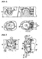
- the sketches 2a and 2b are the processing of the intrados side
- the sketches 2c and 2d are the extrados side
- the sketches 2a and 2c the cross section and the sketches 2b and 2d the plan view. Processing begins on the intrados side by stepwise constrained vertical loops (p1, p3, p5) respectively followed by vertically limited loops (p2, p4, p6).
- the latter begins after reaching the maximum Z-delivery (p5) with centrifugal spiral movement (6) with constantly decreasing Z-delivery up to the preparation margin into the circumscribed free-grinding area with increasing Z-delivery, leaving free webs or holders (13) , After turning the round, the extrados processing takes place. This begins with vertical penetration in the center of the occlusal surface (p7 / BVS) followed by centrifugally spiraling ablation (p8 / VLS). In the outer edge area, another vertical penetration occurs (p9 / BVS).
- Another possibility is to work with the forming penetrating grinding strategy at least in the region (14) enclosed by the retaining webs (13).
- the processing sequences p9 to p12 would be replaced by restricted vertical grinding with subsequent penetration, for example in the position of p9 (FIG. Figure 1 d) followed by forming penetrating loops (15, 14) to the webs (13).
- Figure 3 is a further embodiment (claim 3,4) of the invention outlined in which a direct access to the end face of the blank by a previously ground bridge.
- the partial sketch 3a shows the cross section, the partial sketch 3b the supervision of the intrados side, wherein the processing takes place in the 31/2 axis mode. Due to the (indirect) free access, a rough grinding with a large tool diameter-for example 4mm-is chosen.
- the processing is carried out in chronological order S1 (VLS), S2 (BVS> VLS), roundabout (180 °), S3, S4 and S5.
- the machining process S5 can be done with vertical (FDS) or as outlined here with horizontal (VLS) shaping. It may make sense to combine the two processes in the roughing and finishing process.
- a particularly advantageous effect effect of the invention is the additional processing in the front side position of the blank according to claim 1.
- the partial sketch 4a shows the widespread construction of 31/2-axis or 4 or 5-axis machine versions, in which the workbench is movably mounted on both sides (23) mounted in the A-axis.
- the workbench encloses the Ronde optionally with holder circumferentially (not shown).
- the partial sketches 4a and 4b show, roughly schematically, two embodiments of modified workbenches (24, 25) for the frontal processing, which are provided for conversion.
- In the former (24) find the classic blanks use, which are fixed by clamping action (26).
- the arrangement can be done centrally as usual (27).
- the transverse (30) or upright (31) can be arranged, wherein acts as a clamping surface (26) approximately 1 ⁇ 4 of the height of the blank.
- the remaining remnants of the blanks can be further used by well-known embedding.
- the restorations (32, 33) shown in the blanks (29, 30, 31) are sketched in cross-section in FIG. 5a. Grinding or milling with rollers, discs or lenses or large-caliber tools is another efficient processing strategy.
- disk or lenticular tools enables high rotational speeds with comparatively low rotational speeds, high concentricity and thus extreme substance removal rates, which not only accelerate the roughing process but can also be used efficiently for sizing in s-specific narrow embodiments (see Figures 7 and 8 (77, 78, 94, 95, 99)).
- the cross-sectional removal (36th) shown in FIG. 5h can be achieved by exclusively using the lateral peripheral surface of the tool working part ), even in 31/2-axis or better 32/3-axis operation and even in the roughing process. If now the other positions 5b, 5c, 5e (4-axis operation) are added, the areas (37, 38) of the crown lumen are to be added.
- Another important advantage is to be able to work with extreme inclination angles of the A-axis (in particular 315 °, 45 °), since, in particular, the risk of collision with the workpiece itself and the loss of working-piece proportions is considerably reduced.
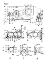
- Figure 6a is another embodiment of a workpiece holder according to claim 12 for rectangular blanks (41) shown (1: 1 scale).
- the ZB 80 Blank (41) (Vita, see above) is glued (43) with an L-shaped frame (42), which can be easily processed by the tool to be used, here diamond grinder (for example, plastic, light metals).
- the frame with workpiece is fixed in the holding device (40) by clamping action, wherein the minimum distance between the workpiece (here: ceramic) and holding device is selected so that the circumference loops (3 mm) can take place in the frame material (44). In this way, it is possible to use the blank without material loss with stable attachment.
- the holding device (40) itself is in turn secured by means of adapter (45) by clamping action on the workbench.
- FIG. 6c represents the detail enlargement of the Figure 6a
- the restoration (48) to be ground is positioned at the boundary with the already used material (49) in the residual material (50).
- the six pages to be edited are labeled with Roman numerals, with side I of the intrados inner side of the crown, side II of the extrados occlusal surface, Page III of the Metados side (here vestibular) and sides IV (here: distal), V (here: mesial) and VI (here: lingual) occupy the remaining sides, where page VI represents the last long side to be machined.
- This assignment of pages is true for the entire description.
- the partial sketches 6a and 6c show the view of the chewing surface (Extrados), the partial sketch 6d the longitudinal sectional view, the partial sketches 6e, 6f, 6g the Que r-sectional representations of partial sketch 6c.
- the machining begins in the meta position (90 °) under a toroidal 5 mm grinder with 0.75 mm edge radius (54).
- this processing step the roughing of the sides II, IV and I according to the grinding line SL1. It follows the grinding in the intrados (0 °) or extrados position (180 °) according to the grinding line SL2, optionally extended by the positions 45 ° (55), 135 ° and 315 ° (56) according to the grinding line SL3 (see also claim 8). It also makes sense, statically even cheaper, to proceed in reverse order.
- the processing of pages III and IV takes place in accordance with SL2 with subsequent processing of pages I and II in Metados position according to SL1. If the machine design and CAM software make this possible, of course, the continuous machining and optionally the 5-axis operation is preferable (claim 8). If the geometric conditions permit, it is advisable to machine the crown lumina according to SL4 as far as possible.
- the rectangular shape and large blanks is preferred according to the invention. This applies not only to the individually pressed oxide ceramics, but in particular for the metal alloys titanium and plastics such as PMMA, nylon, carbon fiber, Teflon, etc., which are available industrially as plate products. From these, rectangular or trapezoidal flat blanks can be particularly cost-effective and economical (water-jet cutting). produce.
- the rather horizontally oriented workpiece surfaces of pages I and II can be machined less efficiently.
- the processing expediently takes place at the adjusted inclination of 30 ° to 45 ° (161).
- the feed paths (165) of the processing pages I, II and III are shown.
- the angle of 75 ° allows the use of the method with machines without equipment laterally open Ronde with a minimum inclination angle of 25 °.
- a further embodiment of the machining strategy according to the invention according to claim 8 includes that a tangential machining along the tangent line with tangent angles between 0 ° and 90 ° (intrados) and 90 ° and 180 ° (extrados) in several fixed steps as in the figures 6 i and j outlined.
- the machining takes place with feed movement aligned parallel to the workpiece axis.
- Einschon listed above caused by the invention effect is to use tools in the form of discs, rollers or lenses can.
- a simple but effective use of disk grinding is represented by the workpiece arrangements shown in Figures 4a and 4b and their use as shown in Figures 5a, 5d and 5e (34).
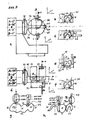
- the band width effect can be extended if the arrangement of the workpiece and the degrees of freedom of its positioning relative to the tool, for example, the in Figure 7 correspond sketched execution.
- the machine design sketched in Figures 7a and 7d is also equipped with a workbench change system (66, for example 3R system).
- This is clearly marked in the area of the A motor, supported by small coordinate systems.
- Each of the four position variants is supplemented with a cross-sectional representation 7b, 7c, 7e, 7f.
- the workpiece holder with two freely accessible end faces (67, 68).
- the sketch 7a shows a classic Ronde (69), which is rigidly fixed in its center by clamping action (67).
- the ronde open from five sides, allows continuous front line work (see above) with at least four freely accessible sides of the dental workpiece (71) until the blank is completely consumed, except for the material covered by, for example, 15mm wide jaws (70).
- the further processing of this residual blank of 15 mm x 100 mm surface has already been discussed above (see also below). The same applies to the positioning in FIG.
- the workbench or workpiece holder (68) is equipped with rectangular blanks in portrait (72) or landscape (73) and therefore the workbench center with clamping device (74) Ax center deviates.
- the covered by the clamping device (75) material can be supplied to the further processing. Since the total height in this arrangement does not exceed 130 mm, usually the diameter of the blank is 100 mm plus the usual 2 x 15 mm worktable wall - this workpiece holder can be used in most machines.
- Another advantage with this arrangement is that in the positioning (nesting) depending on the size of the restorations to be machined the most favorable position in one of the three blanks can be selected in order to avoid unnecessary material consumption.
- Figure 7a is another embodiment of a workpiece holder (67) listed, the clamping device (76) - sketched by dashed line - fixed the blank (69) only on one side.
- the advantageous effect results that three freely accessible end faces (sides) of the blank can be machined.
- Figure 7c illustrates machining options with discs or rollers in position A0-B0. Accordingly, the pages I to III are achieved, in one but unfavorable Position for a shaping process. Also in the A90-B0 position (7e) these pages can be edited. In addition, however, page IV and especially page VI is reached.
- the partial sketches 7b and 7f are very similar and also allow the pre-processing of pages I to III and illustrate that even at extreme tool diameters (7f) the efficiency of the finishing is low. The difference between these seemingly similar machining positions is that in the A0-B90 position (FIG.
- B-axis rotation occurs, for example, +/- 10 ° across an orovestibular (bucolingual) restoration axis (77) or metadata axis or the axis of connection between sides VI and III.
- this pivot axis (78) is perpendicular to the former and parallel to the insertion direction of the restoration (79).
- Figures 7g and 7h illustrate these Achslagen, wherein Figure 7g the supervision of the extrados area and 7h the frontal view represents.
- a particularly efficient processing strategy for the use of disc, roller or lens-shaped tools is the following embodiment according to claim 7.
- the workpiece is machined with a tool axis aligned as parallel as possible to the longitudinal axis of the restoration to be ground.
- this applies to the workpiece (71) in A 0-B 90-position
- Figure 7d for the workpiece (73) A 90-B 90 position.
- the corresponding cross-sectional views 7b and 7d illustrate the advantageous effects.
- the machining is done by trimming the workpiece contour according to an alternating feed movement (95) from the sides I to III to II and then in reverse order at a parallel to the longitudinal axis of the restoration applied delivery.
- the trapezoidal shape allows the achievement of the surfaces I to III over the entire dental arch (restoration arch) and thus its frontal processing.
- machining There are different forms of machining to distinguish, which will be explained with reference to an embodiment of a machining sequence for metals.
- the process begins with drilling or cramped vertical milling of the crown lumens and connecting holes (87). This is followed by rapid cutting (claim 10) (Rapid Cutting) (88) with thin sawing discs for metalworking with diameters of 30 mm (6-shank, cutting depth up to 12 mm) up to 60 mm (8-shank, cutting depth up to 26 mm).
- FIG. 8b In the anterior region ( Figure 8b ), the angle adjustment takes place by means of B-axis adjustments (91, 92, 93).
- the illustrations in Figures 6c and 6d can be used.
- the toroidal grinder (54) is to be replaced by the rollers or side milling cutter.
- the grinding line SL1 then corresponds to the processing of the surfaces I and II
- the grinding line SL2 corresponds to the processing of the surface III.
- Figures 8b and 8c illustrate the additional possibility of pivoting the workpiece according to the angle ⁇ with 20 ° and the angle ⁇ with 25 °. This is especially important with regard to the risk of collision.
- the final processing of page VI can also take place with disk or cylindrical tools (97). This can on the one hand in the manner of penetrating processing - to avoid too large tool diameter is preferable to double-sided machining (99, Figures 7e, 8c) - or on the other hand by vertically limited penetration (98, Figures 5d, 5g) taking out holding webs or straps.
- the detrimental effect of the slice cut especially for small dental arch radii (front inside) can be reduced by connecting holes (87).
- Post-processing in the classical machining process with radius cutters or torus cutters is essential. Finally, the finishing of the page Vl.
- This is composed of a U-shaped work table frame (101), which is fixedly connected on both sides (23) with the A-axle bearings, and a replaceable, to be fastened by screwing workbench insert (102) together.
- the framework in its periphery (103) has been strengthened.
- Any workbench insert is equipped with two ball latches or repositioning pins (104), which snap into the corresponding position holes on the work table frame, so that an exact repossibility of all workbench inserts is guaranteed.
- Figures 9a and 9b show the closed workbench insert (102) for the direct introduction of a classic blank (107), which is fastened by clamping ring (109) and clamping screw (110).
- Figures 9c to 9g show workbench inserts for cuboidal blanks (111) that are open on one side.
- the workpiece is fastened by a respective clamping plate (112), which is fastened by means of screwing force (113) to the work table insert functioning as the base plate (114).
- a significant advantage of this embodiment is that a large portion of the workpiece (111) in the clamping device (112, 113, 114) is fixed and only the necessary for processing proportion of five pages is freely accessible. In this way a high mounting stability and low vibration is realized at the same time maximum free access.
- a particularly advantageous embodiment is the arrangement sketched in FIGS. 9f and 9g.
- D 36 mm
- the use of comparatively inexpensive rod materials titanium, CoCr steels
- the above-mentioned residual materials can also optionally be used after pre-processing, as can all the blanks of the Cerec and Celay system. This applies equally to the arrangement sketched in subfigure 9e.
- adapters (120) which are to be mounted on the base plate (114).
- maximum size of 20 mm x 20 mm requires a desired blank with the dimension 20 mm x 12 mm an adapter with a thickness of 4 mm.
- FIG. 9 h and i A particularly advantageous embodiment according to claim 13 of a workpiece attachment is sketched in Figures 9 h and i.
- a secondary attachment between the workpiece (41) and the work table (46) on the workpiece holder (45) and workpiece frame (42) takes place and the primary attachment of the workpiece material by means of a likewise on the work table (46) attached removable clamping device, which consists of a Base plate (180) with fastening screws (183) and a counter plate (181) with clamping screws (184) and the access (182) to the secondary clamping device (40) omits takes place, wherein upon activation of the primary clamping action (185) Preferably, the minor repeal of the secondary clamping device takes place to avoid stresses and in reverse order after completion of the first and beginning of the second processing step.
- the Ronde is provided at the end face of its 10 mm high and 2 mm projecting heel (121) with a vertical, for example U- or V-shaped notch (128) into which the congruent counterpart of Clamping device (123) in the region of the axis in the form of a wedge (124) engages.
- a vertical, for example U- or V-shaped notch (128) into which the congruent counterpart of Clamping device (123) in the region of the axis in the form of a wedge (124) engages.
- the function of this reduction aid is to avoid displacements in the direction of the A-axis (126) and rotations about the vertical axis of the blank (127).
- a precise re-attachment of the blank in the sense of any rotation about the A-axis by itself by the clamping action is possible to exchange with just a clamping device round blanks with exact repossibility and the cost-intensive quick-change systems or on the use of multiple clamping devices to be able to do without.
- the attachment of a reduction aid can also be additive, for example, by gluing a prefabricated round rod made of transparent PMMA plastic in said position by means of an auxiliary apparatus and light-curing plastic to the end face of the Ronde paragraph.
- This type of blanks attachment is also suitable for in Figure 4a illustrated embodiment and also in combination with the work table inserts (102) in bilaterally mounted versions.
- a particularly advantageous embodiment results when the two workpiece plates are in direct contact with each other, wherein the contact surface (136) contains the A-axis and can be defined as Indrados or Ertrados surface.
- the blank (111) shown there is replaced by the two blanks (134, 135).
- the upper blank (135) can be chosen freely in its thickness, since it has no influence on the centering of the contact surface (136).
- the thickness of the lower blank (134) is determined according to the base plate dimension. It is therefore appropriate to make the base plate (114) such that it is intended to receive a particular blank, for example the one of the maximum thickness (20 mm) or the most common (10 mm). In the former case, if one wishes to use a smaller blank, then it is possible to compensate for this difference in thickness dimensions by shims.
- a particularly advantageous embodiment of such a double workpiece holder illustrates the modified cross-sectional view of Figure 11 b.
- the thickness dimensions of the blanks have no influence on the centered in the A-axis contact surface (132, 133), since the upper blank (130) on the plateau (142) one base plate side (140) and the lower blank (131) on the Plateau (143) of the right base plate side (141) rests. Both blanks lie on the opposite side of their plateau edition again directly on the opposite blank.
- the connection of the two base plate sides (140, 141) takes place over the peripheral frame (144) covered by the clamping plates (112).
- the widely used single tooth blanks with metallic fixing pins for the CEREC and CELAY systems can be machined conventionally in known fixtures with up to eight single tooth blanks in many machines. Since the blanks according to the derivation of round blank holders point respectively to the center of the worktable, they are not accessible to a frontal processing.
- Figure 12 two CEREC holders for all processing strategies according to the invention are shown, which also allow the processing of up to 14 blocks. Their number could be further increased by reducing the spacing between the individual blocks from 18 mm to 3.2 mm.
- Figures 12a and c show the holding device in the frontal cross-section in the basic positions.
- As tool (146), an 18 mm roller with H 2 mm in the basic position (A0BO) is sketched. Three blocks (147) are arranged in series. The in the front (III, II) and background (IV, III) arranged blocks (148) are equally editable after appropriate A-axis adjustment.
- the blanks (147, 148, 149) would then be arranged on a half or 3/4 ball.
- the three-legged arrangement (7c, 7d) proves the space gain for the freedom of movement of the spindle, which acts with respect to the cross-shaped (7a, b) arrangement with a factor of 1.75 (D, 1.75 x D).
- Figure 13 is a hydraulic, centering exciting vise (150) with interchangeable jaws (151) outlined roughly simplified. This design allows for easy and fast attachment of the blanks (152) optionally with adapter (154) and allows for many machine designs, limited by the machine geometry (153), length dimensions of the workpieces of 140 mm.
- Hold-free blanks (E-max C14 Fa. Ivoclar, BZ 33 Fa. Vita) can be bonded after pretreatment (sandblasting, conditioning, bonding agent) with miniature versions of the "L" -shaped frame, with its clamping device at its mounting base with a CEREC pin are equipped.
Landscapes
- Health & Medical Sciences (AREA)
- Life Sciences & Earth Sciences (AREA)
- General Health & Medical Sciences (AREA)
- Surgery (AREA)
- Veterinary Medicine (AREA)
- Public Health (AREA)
- Animal Behavior & Ethology (AREA)
- Engineering & Computer Science (AREA)
- Biophysics (AREA)
- Pathology (AREA)
- Dentistry (AREA)
- Physics & Mathematics (AREA)
- Oral & Maxillofacial Surgery (AREA)
- Nuclear Medicine, Radiotherapy & Molecular Imaging (AREA)
- Optics & Photonics (AREA)
- Epidemiology (AREA)
- Radiology & Medical Imaging (AREA)
- Molecular Biology (AREA)
- Biomedical Technology (AREA)
- Heart & Thoracic Surgery (AREA)
- Medical Informatics (AREA)
- Manufacturing & Machinery (AREA)
- Grinding And Polishing Of Tertiary Curved Surfaces And Surfaces With Complex Shapes (AREA)
- Dental Prosthetics (AREA)
Applications Claiming Priority (1)
| Application Number | Priority Date | Filing Date | Title |
|---|---|---|---|
| DE102010061116.6A DE102010061116B4 (de) | 2010-12-08 | 2010-12-08 | Verfahren zur Herstellung von dentalen Werkstücken |
Publications (3)
| Publication Number | Publication Date |
|---|---|
| EP2462894A2 true EP2462894A2 (fr) | 2012-06-13 |
| EP2462894A3 EP2462894A3 (fr) | 2014-12-24 |
| EP2462894B1 EP2462894B1 (fr) | 2017-10-25 |
Family
ID=45218610
Family Applications (1)
| Application Number | Title | Priority Date | Filing Date |
|---|---|---|---|
| EP11401657.9A Active EP2462894B1 (fr) | 2010-12-08 | 2011-12-06 | Procédé de fabrication de pièces dentaires |
Country Status (2)
| Country | Link |
|---|---|
| EP (1) | EP2462894B1 (fr) |
| DE (1) | DE102010061116B4 (fr) |
Cited By (2)
| Publication number | Priority date | Publication date | Assignee | Title |
|---|---|---|---|---|
| AT516840B1 (de) * | 2015-04-30 | 2016-09-15 | Steger Heinrich | Rohling zur Herstellung eines Dentalelements |
| DE202016007641U1 (de) * | 2016-12-19 | 2018-03-20 | Isel Facility GmbH | Blank-Halter einer Dentalfräsmaschine |
Families Citing this family (3)
| Publication number | Priority date | Publication date | Assignee | Title |
|---|---|---|---|---|
| AT516263B1 (de) | 2015-01-21 | 2016-04-15 | Steger Heinrich | Haltevorrichtung für ein dentales Werkstück |
| EP3332737B1 (fr) * | 2016-12-12 | 2022-10-12 | Martin Huber | Procédé de production d'une partie de restauration dentaire et machine d'usinage dentaire |
| EP4306074B1 (fr) * | 2022-07-14 | 2025-05-21 | Ivoclar Vivadent AG | Appareil de fabrication pour une prothèse dentaire |
Family Cites Families (5)
| Publication number | Priority date | Publication date | Assignee | Title |
|---|---|---|---|---|
| CH663891A5 (de) * | 1984-10-24 | 1988-01-29 | Marco Dr Sc Techn Brandestini | Vorrichtung fuer die formgebende bearbeitung eines rohlings aus dentalkeramischem oder dentalem komposit-material und verfahren zu deren betrieb. |
| DE19930859A1 (de) | 1999-07-05 | 2001-01-18 | Sirona Dental Systems Gmbh | Verfahren zur Erstellung von medizinischen, insbesondere zahnmedizinischen Paßkörpern |
| DE10150647A1 (de) | 2001-10-13 | 2003-04-30 | Rauter Vita Zahnfabrik | Verfahren und Formelement zur Herstellung von Zahnersatz |
| DE10156156B4 (de) | 2001-11-15 | 2005-04-21 | 3M Espe Ag | Verfahren zur Herstellung von Zahnersatz |
| DE102005001600B4 (de) | 2004-11-30 | 2011-08-18 | FOLLOW ME! Technology Systems GmbH, 81675 | Verfahren zur Material abtragenden Bearbeitung von Werkstücken und Werkstück bzw. Formelement |
-
2010
- 2010-12-08 DE DE102010061116.6A patent/DE102010061116B4/de active Active
-
2011
- 2011-12-06 EP EP11401657.9A patent/EP2462894B1/fr active Active
Non-Patent Citations (1)
| Title |
|---|
| None |
Cited By (4)
| Publication number | Priority date | Publication date | Assignee | Title |
|---|---|---|---|---|
| AT516840B1 (de) * | 2015-04-30 | 2016-09-15 | Steger Heinrich | Rohling zur Herstellung eines Dentalelements |
| AT516840A4 (de) * | 2015-04-30 | 2016-09-15 | Steger Heinrich | Rohling zur Herstellung eines Dentalelements |
| EP3216420A1 (fr) | 2015-04-30 | 2017-09-13 | STEGER, Heinrich | Ébauche destinée à fabriquer une prothèse dentaire |
| DE202016007641U1 (de) * | 2016-12-19 | 2018-03-20 | Isel Facility GmbH | Blank-Halter einer Dentalfräsmaschine |
Also Published As
| Publication number | Publication date |
|---|---|
| EP2462894A3 (fr) | 2014-12-24 |
| DE102010061116A1 (de) | 2012-06-14 |
| EP2462894B1 (fr) | 2017-10-25 |
| DE102010061116B4 (de) | 2022-01-13 |
Similar Documents
| Publication | Publication Date | Title |
|---|---|---|
| EP2844183B1 (fr) | Procédé de fraisage permettant de produire des pièces de prothèse dentaire | |
| EP2367656B2 (fr) | Machine-outil et procédé de fabrication de dentures | |
| EP1291106B1 (fr) | Méthode et appareil pour le machinage de surface de pièces en matériaux non fragiles dans la fabrication d'optiques, et outil associé | |
| DE10112286C1 (de) | Verfahren zur Herstellung eines chirurgischen Sägeblatts | |
| EP2247405B1 (fr) | Dispositif de fixation pour une machine d'usinage par enlèvement de copeaux pilotée par ordinateur | |
| EP0182098B1 (fr) | Procédé et dispositif pour la fabrication d'un corps restauratif de dent apte à être utilisé individuellement | |
| EP3758876B1 (fr) | Outil de chanfreinage, système de chanfreinage, machine à tailler des dentures et procédé servant à chanfreiner des dentures | |
| EP1422005B1 (fr) | Procédé et dispositif pour l'usinage du bord de lentilles ophtalmiques en plastique | |
| EP1168978B1 (fr) | Procede de production d'instruments endodontiques | |
| EP2823924A2 (fr) | Machine à dresser double | |
| EP1577041B1 (fr) | Machine et procédé correspondant de taillage de roues dentées coniques pour la chanfreinage et l'ébavaurage des extrémités de dents des roues dentées coniques | |
| EP2462894B1 (fr) | Procédé de fabrication de pièces dentaires | |
| DE20105248U1 (de) | Fräs-/Schleifmaschine zur Herstellung von zahnmedizinischen Werkstücken | |
| DE202016103064U1 (de) | Vorrichtung zur spanenden Bearbeitung eines rotierenden Werkstücks | |
| EP1060712A3 (fr) | Dispositif et procédé de fabrication de prothèses dentaires | |
| EP3332737B1 (fr) | Procédé de production d'une partie de restauration dentaire et machine d'usinage dentaire | |
| DE102011082979A1 (de) | Reibwerkzeug und Verfahren zu dessen Herstellung | |
| DE102005001600B4 (de) | Verfahren zur Material abtragenden Bearbeitung von Werkstücken und Werkstück bzw. Formelement | |
| DE202019001722U1 (de) | Anfasanordnung | |
| DE102017009588B4 (de) | Bearbeitungsmaschine zum Bearbeiten eines Blocks für Zahnprothesen, Verfahren zum Polieren eines Bearbeitungswerkzeugs und Verfahren zum Herstellen von Zahnprothesen | |
| KR102127075B1 (ko) | 스피로이드 베벨 기어의 가공 공구 | |
| EP2465463A1 (fr) | Procédé et dispositif de fabrication de prothèses dentaires extra-orales | |
| DE102017129651A1 (de) | Verfahren zur Verzahnbearbeitung eines Werkstücks | |
| DE102005063549B4 (de) | Werkstück bzw. Formelement, Verfahren zur Material abtragenden Bearbeitung von Werkstücken, Maschinensteuerungsprogramm und Bearbeitungsvorrichtung | |
| DE2217288B2 (de) | Einrichtung an einer Drehmaschine zum Herstellen von Nuten an drehsymmetrischen Werkstücken |
Legal Events
| Date | Code | Title | Description |
|---|---|---|---|
| PUAI | Public reference made under article 153(3) epc to a published international application that has entered the european phase |
Free format text: ORIGINAL CODE: 0009012 |
|
| AK | Designated contracting states |
Kind code of ref document: A2 Designated state(s): AL AT BE BG CH CY CZ DE DK EE ES FI FR GB GR HR HU IE IS IT LI LT LU LV MC MK MT NL NO PL PT RO RS SE SI SK SM TR |
|
| AX | Request for extension of the european patent |
Extension state: BA ME |
|
| RIC1 | Information provided on ipc code assigned before grant |
Ipc: A61C 13/00 20060101AFI20140124BHEP |
|
| PUAL | Search report despatched |
Free format text: ORIGINAL CODE: 0009013 |
|
| AK | Designated contracting states |
Kind code of ref document: A3 Designated state(s): AL AT BE BG CH CY CZ DE DK EE ES FI FR GB GR HR HU IE IS IT LI LT LU LV MC MK MT NL NO PL PT RO RS SE SI SK SM TR |
|
| AX | Request for extension of the european patent |
Extension state: BA ME |
|
| RIC1 | Information provided on ipc code assigned before grant |
Ipc: A61C 13/00 20060101AFI20141114BHEP Ipc: A61C 5/10 20060101ALI20141114BHEP |
|
| 17P | Request for examination filed |
Effective date: 20150429 |
|
| RBV | Designated contracting states (corrected) |
Designated state(s): AL AT BE BG CH CY CZ DE DK EE ES FI FR GB GR HR HU IE IS IT LI LT LU LV MC MK MT NL NO PL PT RO RS SE SI SK SM TR |
|
| 17Q | First examination report despatched |
Effective date: 20160323 |
|
| RIC1 | Information provided on ipc code assigned before grant |
Ipc: A61C 13/00 20060101AFI20170530BHEP Ipc: A61C 5/77 20170101ALI20170530BHEP |
|
| GRAP | Despatch of communication of intention to grant a patent |
Free format text: ORIGINAL CODE: EPIDOSNIGR1 |
|
| STAA | Information on the status of an ep patent application or granted ep patent |
Free format text: STATUS: GRANT OF PATENT IS INTENDED |
|
| INTG | Intention to grant announced |
Effective date: 20170713 |
|
| GRAS | Grant fee paid |
Free format text: ORIGINAL CODE: EPIDOSNIGR3 |
|
| GRAA | (expected) grant |
Free format text: ORIGINAL CODE: 0009210 |
|
| STAA | Information on the status of an ep patent application or granted ep patent |
Free format text: STATUS: THE PATENT HAS BEEN GRANTED |
|
| AK | Designated contracting states |
Kind code of ref document: B1 Designated state(s): AL AT BE BG CH CY CZ DE DK EE ES FI FR GB GR HR HU IE IS IT LI LT LU LV MC MK MT NL NO PL PT RO RS SE SI SK SM TR |
|
| REG | Reference to a national code |
Ref country code: GB Ref legal event code: FG4D Free format text: NOT ENGLISH |
|
| REG | Reference to a national code |
Ref country code: CH Ref legal event code: EP |
|
| REG | Reference to a national code |
Ref country code: AT Ref legal event code: REF Ref document number: 939175 Country of ref document: AT Kind code of ref document: T Effective date: 20171115 |
|
| REG | Reference to a national code |
Ref country code: IE Ref legal event code: FG4D Free format text: LANGUAGE OF EP DOCUMENT: GERMAN |
|
| REG | Reference to a national code |
Ref country code: DE Ref legal event code: R096 Ref document number: 502011013182 Country of ref document: DE |
|
| REG | Reference to a national code |
Ref country code: FR Ref legal event code: PLFP Year of fee payment: 7 |
|
| REG | Reference to a national code |
Ref country code: NL Ref legal event code: MP Effective date: 20171025 |
|
| REG | Reference to a national code |
Ref country code: LT Ref legal event code: MG4D |
|
| PG25 | Lapsed in a contracting state [announced via postgrant information from national office to epo] |
Ref country code: NL Free format text: LAPSE BECAUSE OF FAILURE TO SUBMIT A TRANSLATION OF THE DESCRIPTION OR TO PAY THE FEE WITHIN THE PRESCRIBED TIME-LIMIT Effective date: 20171025 |
|
| PG25 | Lapsed in a contracting state [announced via postgrant information from national office to epo] |
Ref country code: LT Free format text: LAPSE BECAUSE OF FAILURE TO SUBMIT A TRANSLATION OF THE DESCRIPTION OR TO PAY THE FEE WITHIN THE PRESCRIBED TIME-LIMIT Effective date: 20171025 Ref country code: ES Free format text: LAPSE BECAUSE OF FAILURE TO SUBMIT A TRANSLATION OF THE DESCRIPTION OR TO PAY THE FEE WITHIN THE PRESCRIBED TIME-LIMIT Effective date: 20171025 Ref country code: NO Free format text: LAPSE BECAUSE OF FAILURE TO SUBMIT A TRANSLATION OF THE DESCRIPTION OR TO PAY THE FEE WITHIN THE PRESCRIBED TIME-LIMIT Effective date: 20180125 Ref country code: FI Free format text: LAPSE BECAUSE OF FAILURE TO SUBMIT A TRANSLATION OF THE DESCRIPTION OR TO PAY THE FEE WITHIN THE PRESCRIBED TIME-LIMIT Effective date: 20171025 Ref country code: SE Free format text: LAPSE BECAUSE OF FAILURE TO SUBMIT A TRANSLATION OF THE DESCRIPTION OR TO PAY THE FEE WITHIN THE PRESCRIBED TIME-LIMIT Effective date: 20171025 |
|
| PG25 | Lapsed in a contracting state [announced via postgrant information from national office to epo] |
Ref country code: IS Free format text: LAPSE BECAUSE OF FAILURE TO SUBMIT A TRANSLATION OF THE DESCRIPTION OR TO PAY THE FEE WITHIN THE PRESCRIBED TIME-LIMIT Effective date: 20180225 Ref country code: BG Free format text: LAPSE BECAUSE OF FAILURE TO SUBMIT A TRANSLATION OF THE DESCRIPTION OR TO PAY THE FEE WITHIN THE PRESCRIBED TIME-LIMIT Effective date: 20180125 Ref country code: RS Free format text: LAPSE BECAUSE OF FAILURE TO SUBMIT A TRANSLATION OF THE DESCRIPTION OR TO PAY THE FEE WITHIN THE PRESCRIBED TIME-LIMIT Effective date: 20171025 Ref country code: HR Free format text: LAPSE BECAUSE OF FAILURE TO SUBMIT A TRANSLATION OF THE DESCRIPTION OR TO PAY THE FEE WITHIN THE PRESCRIBED TIME-LIMIT Effective date: 20171025 Ref country code: GR Free format text: LAPSE BECAUSE OF FAILURE TO SUBMIT A TRANSLATION OF THE DESCRIPTION OR TO PAY THE FEE WITHIN THE PRESCRIBED TIME-LIMIT Effective date: 20180126 Ref country code: LV Free format text: LAPSE BECAUSE OF FAILURE TO SUBMIT A TRANSLATION OF THE DESCRIPTION OR TO PAY THE FEE WITHIN THE PRESCRIBED TIME-LIMIT Effective date: 20171025 |
|
| REG | Reference to a national code |
Ref country code: DE Ref legal event code: R097 Ref document number: 502011013182 Country of ref document: DE |
|
| PG25 | Lapsed in a contracting state [announced via postgrant information from national office to epo] |
Ref country code: DK Free format text: LAPSE BECAUSE OF FAILURE TO SUBMIT A TRANSLATION OF THE DESCRIPTION OR TO PAY THE FEE WITHIN THE PRESCRIBED TIME-LIMIT Effective date: 20171025 Ref country code: CZ Free format text: LAPSE BECAUSE OF FAILURE TO SUBMIT A TRANSLATION OF THE DESCRIPTION OR TO PAY THE FEE WITHIN THE PRESCRIBED TIME-LIMIT Effective date: 20171025 Ref country code: EE Free format text: LAPSE BECAUSE OF FAILURE TO SUBMIT A TRANSLATION OF THE DESCRIPTION OR TO PAY THE FEE WITHIN THE PRESCRIBED TIME-LIMIT Effective date: 20171025 Ref country code: CY Free format text: LAPSE BECAUSE OF FAILURE TO SUBMIT A TRANSLATION OF THE DESCRIPTION OR TO PAY THE FEE WITHIN THE PRESCRIBED TIME-LIMIT Effective date: 20171025 Ref country code: SK Free format text: LAPSE BECAUSE OF FAILURE TO SUBMIT A TRANSLATION OF THE DESCRIPTION OR TO PAY THE FEE WITHIN THE PRESCRIBED TIME-LIMIT Effective date: 20171025 |
|
| REG | Reference to a national code |
Ref country code: CH Ref legal event code: PL |
|
| PG25 | Lapsed in a contracting state [announced via postgrant information from national office to epo] |
Ref country code: RO Free format text: LAPSE BECAUSE OF FAILURE TO SUBMIT A TRANSLATION OF THE DESCRIPTION OR TO PAY THE FEE WITHIN THE PRESCRIBED TIME-LIMIT Effective date: 20171025 Ref country code: IT Free format text: LAPSE BECAUSE OF FAILURE TO SUBMIT A TRANSLATION OF THE DESCRIPTION OR TO PAY THE FEE WITHIN THE PRESCRIBED TIME-LIMIT Effective date: 20171025 Ref country code: SM Free format text: LAPSE BECAUSE OF FAILURE TO SUBMIT A TRANSLATION OF THE DESCRIPTION OR TO PAY THE FEE WITHIN THE PRESCRIBED TIME-LIMIT Effective date: 20171025 Ref country code: PL Free format text: LAPSE BECAUSE OF FAILURE TO SUBMIT A TRANSLATION OF THE DESCRIPTION OR TO PAY THE FEE WITHIN THE PRESCRIBED TIME-LIMIT Effective date: 20171025 |
|
| PLBE | No opposition filed within time limit |
Free format text: ORIGINAL CODE: 0009261 |
|
| STAA | Information on the status of an ep patent application or granted ep patent |
Free format text: STATUS: NO OPPOSITION FILED WITHIN TIME LIMIT |
|
| REG | Reference to a national code |
Ref country code: IE Ref legal event code: MM4A |
|
| GBPC | Gb: european patent ceased through non-payment of renewal fee |
Effective date: 20180125 |
|
| PG25 | Lapsed in a contracting state [announced via postgrant information from national office to epo] |
Ref country code: LU Free format text: LAPSE BECAUSE OF NON-PAYMENT OF DUE FEES Effective date: 20171206 Ref country code: MT Free format text: LAPSE BECAUSE OF FAILURE TO SUBMIT A TRANSLATION OF THE DESCRIPTION OR TO PAY THE FEE WITHIN THE PRESCRIBED TIME-LIMIT Effective date: 20171025 |
|
| 26N | No opposition filed |
Effective date: 20180726 |
|
| REG | Reference to a national code |
Ref country code: BE Ref legal event code: MM Effective date: 20171231 |
|
| PG25 | Lapsed in a contracting state [announced via postgrant information from national office to epo] |
Ref country code: IE Free format text: LAPSE BECAUSE OF NON-PAYMENT OF DUE FEES Effective date: 20171206 |
|
| PG25 | Lapsed in a contracting state [announced via postgrant information from national office to epo] |
Ref country code: BE Free format text: LAPSE BECAUSE OF NON-PAYMENT OF DUE FEES Effective date: 20171231 Ref country code: SI Free format text: LAPSE BECAUSE OF FAILURE TO SUBMIT A TRANSLATION OF THE DESCRIPTION OR TO PAY THE FEE WITHIN THE PRESCRIBED TIME-LIMIT Effective date: 20171025 Ref country code: LI Free format text: LAPSE BECAUSE OF NON-PAYMENT OF DUE FEES Effective date: 20171231 Ref country code: GB Free format text: LAPSE BECAUSE OF NON-PAYMENT OF DUE FEES Effective date: 20180125 Ref country code: CH Free format text: LAPSE BECAUSE OF NON-PAYMENT OF DUE FEES Effective date: 20171231 |
|
| REG | Reference to a national code |
Ref country code: AT Ref legal event code: MM01 Ref document number: 939175 Country of ref document: AT Kind code of ref document: T Effective date: 20171206 |
|
| PG25 | Lapsed in a contracting state [announced via postgrant information from national office to epo] |
Ref country code: AT Free format text: LAPSE BECAUSE OF NON-PAYMENT OF DUE FEES Effective date: 20171206 |
|
| PG25 | Lapsed in a contracting state [announced via postgrant information from national office to epo] |
Ref country code: MC Free format text: LAPSE BECAUSE OF FAILURE TO SUBMIT A TRANSLATION OF THE DESCRIPTION OR TO PAY THE FEE WITHIN THE PRESCRIBED TIME-LIMIT Effective date: 20171025 Ref country code: HU Free format text: LAPSE BECAUSE OF FAILURE TO SUBMIT A TRANSLATION OF THE DESCRIPTION OR TO PAY THE FEE WITHIN THE PRESCRIBED TIME-LIMIT; INVALID AB INITIO Effective date: 20111206 |
|
| PG25 | Lapsed in a contracting state [announced via postgrant information from national office to epo] |
Ref country code: MK Free format text: LAPSE BECAUSE OF FAILURE TO SUBMIT A TRANSLATION OF THE DESCRIPTION OR TO PAY THE FEE WITHIN THE PRESCRIBED TIME-LIMIT Effective date: 20171025 |
|
| PG25 | Lapsed in a contracting state [announced via postgrant information from national office to epo] |
Ref country code: TR Free format text: LAPSE BECAUSE OF FAILURE TO SUBMIT A TRANSLATION OF THE DESCRIPTION OR TO PAY THE FEE WITHIN THE PRESCRIBED TIME-LIMIT Effective date: 20171025 |
|
| PG25 | Lapsed in a contracting state [announced via postgrant information from national office to epo] |
Ref country code: PT Free format text: LAPSE BECAUSE OF FAILURE TO SUBMIT A TRANSLATION OF THE DESCRIPTION OR TO PAY THE FEE WITHIN THE PRESCRIBED TIME-LIMIT Effective date: 20171025 |
|
| PG25 | Lapsed in a contracting state [announced via postgrant information from national office to epo] |
Ref country code: AL Free format text: LAPSE BECAUSE OF FAILURE TO SUBMIT A TRANSLATION OF THE DESCRIPTION OR TO PAY THE FEE WITHIN THE PRESCRIBED TIME-LIMIT Effective date: 20171025 |
|
| PGFP | Annual fee paid to national office [announced via postgrant information from national office to epo] |
Ref country code: FR Payment date: 20201218 Year of fee payment: 10 |
|
| PG25 | Lapsed in a contracting state [announced via postgrant information from national office to epo] |
Ref country code: FR Free format text: LAPSE BECAUSE OF NON-PAYMENT OF DUE FEES Effective date: 20211231 |
|
| REG | Reference to a national code |
Ref country code: DE Ref legal event code: R082 Ref document number: 502011013182 Country of ref document: DE Representative=s name: CREUTZBURG, TOM, DIPL.-ING., DE |
|
| PGFP | Annual fee paid to national office [announced via postgrant information from national office to epo] |
Ref country code: DE Payment date: 20241231 Year of fee payment: 14 |
|
| REG | Reference to a national code |
Ref country code: DE Ref legal event code: R082 Ref document number: 502011013182 Country of ref document: DE |