EP3216420A1 - Ébauche destinée à fabriquer une prothèse dentaire - Google Patents
Ébauche destinée à fabriquer une prothèse dentaire Download PDFInfo
- Publication number
- EP3216420A1 EP3216420A1 EP17165754.7A EP17165754A EP3216420A1 EP 3216420 A1 EP3216420 A1 EP 3216420A1 EP 17165754 A EP17165754 A EP 17165754A EP 3216420 A1 EP3216420 A1 EP 3216420A1
- Authority
- EP
- European Patent Office
- Prior art keywords
- blanks
- clamping
- blank
- holding
- clamped
- Prior art date
- Legal status (The legal status is an assumption and is not a legal conclusion. Google has not performed a legal analysis and makes no representation as to the accuracy of the status listed.)
- Granted
Links
Images


Classifications
-
- A—HUMAN NECESSITIES
- A61—MEDICAL OR VETERINARY SCIENCE; HYGIENE
- A61C—DENTISTRY; APPARATUS OR METHODS FOR ORAL OR DENTAL HYGIENE
- A61C13/00—Dental prostheses; Making same
- A61C13/0003—Making bridge-work, inlays, implants or the like
- A61C13/0022—Blanks or green, unfinished dental restoration parts
-
- A—HUMAN NECESSITIES
- A61—MEDICAL OR VETERINARY SCIENCE; HYGIENE
- A61C—DENTISTRY; APPARATUS OR METHODS FOR ORAL OR DENTAL HYGIENE
- A61C13/00—Dental prostheses; Making same
-
- A—HUMAN NECESSITIES
- A61—MEDICAL OR VETERINARY SCIENCE; HYGIENE
- A61C—DENTISTRY; APPARATUS OR METHODS FOR ORAL OR DENTAL HYGIENE
- A61C5/00—Filling or capping teeth
- A61C5/70—Tooth crowns; Making thereof
- A61C5/77—Methods or devices for making crowns
-
- A—HUMAN NECESSITIES
- A61—MEDICAL OR VETERINARY SCIENCE; HYGIENE
- A61C—DENTISTRY; APPARATUS OR METHODS FOR ORAL OR DENTAL HYGIENE
- A61C13/00—Dental prostheses; Making same
- A61C13/12—Tools for fastening artificial teeth; Holders, clamps, or stands for artificial teeth
-
- B—PERFORMING OPERATIONS; TRANSPORTING
- B23—MACHINE TOOLS; METAL-WORKING NOT OTHERWISE PROVIDED FOR
- B23C—MILLING
- B23C2226/00—Materials of tools or workpieces not comprising a metal
- B23C2226/18—Ceramic
-
- B—PERFORMING OPERATIONS; TRANSPORTING
- B23—MACHINE TOOLS; METAL-WORKING NOT OTHERWISE PROVIDED FOR
- B23C—MILLING
- B23C2240/00—Details of connections of tools or workpieces
-
- Y—GENERAL TAGGING OF NEW TECHNOLOGICAL DEVELOPMENTS; GENERAL TAGGING OF CROSS-SECTIONAL TECHNOLOGIES SPANNING OVER SEVERAL SECTIONS OF THE IPC; TECHNICAL SUBJECTS COVERED BY FORMER USPC CROSS-REFERENCE ART COLLECTIONS [XRACs] AND DIGESTS
- Y10—TECHNICAL SUBJECTS COVERED BY FORMER USPC
- Y10T—TECHNICAL SUBJECTS COVERED BY FORMER US CLASSIFICATION
- Y10T409/00—Gear cutting, milling, or planing
- Y10T409/30—Milling
Definitions
- the invention relates to an arrangement with two blanks and a holding device for holding the two blanks, wherein the two blanks each have a first side formed as a front side and a rear side formed as a second side.
- Such a holding or clamping two blanks in a work table insert goes out of the DE 10 2010 061 116 A1 (equals to EP 2 462 894 A2 ) and in particular from Figure 9.1d.
- the two clamped blanks abut each other via a contact surface.
- the disadvantage is that these blanks are clamped over a large part of the front and rear sides in the work table insert. Thus, only a small protruding area is even editable.
- the object of the present invention is therefore to provide an arrangement which allows a simple and effective processing of two clamped blanks.
- both blanks have at least one auxiliary holding surface spaced from the rear side for holding the blank on a holding device, wherein the blank has a special holding thickness between the at least one auxiliary holding surface and the rear side and wherein the standard holding thickness is twice as large how the special holding thicknesses are.
- the holding device has at least one, preferably three, clamping device, wherein the blanks are clamped on their auxiliary holding surfaces of de clamping device on the holding device.
- each clamping device has a movable clamping part and a clamping surface, wherein in the clamped state, an auxiliary holding surface of a blank rests on the clamping surface and an auxiliary holding surface of the other blank rests on the clamping part.
- each clamping device has a movable clamping part and a clamping surface, wherein in the clamped state, an auxiliary holding surface of a blank rests on the clamping surface and an auxiliary holding surface of the other blank rests on the clamping part.
- the clamping device is suitable to clamp different thickness blanks.
- the clamping device can have mutually adjustable clamping parts and clamping surfaces.
- the movable clamping part and the clamping surface of the clamping device to each other have a substantially invariable, preferably the standard holding thickness corresponding distance.
- both a blank and two blank can be clamped in one and the same, simple clamping device.
- the blanks do not have to touch each other when clamped over their backs.
- the blanks in the clamped state over the mutually facing backs partially or completely abut each other.
- such an arrangement also has a processing device for processing the two blanks clamped in the holding device, wherein both blanks can be processed by the processing device via the substantially completely accessible front sides.
- the processing device and the holding device are relatively movable relative to each other, that both front sides are machined.
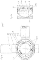
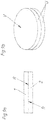
- Fig. 1a shows a holding device 3 for a blank 1, 2, as it has been manufactured for some time by the Applicant, offered and sold.
- a holding device has a substantially C-shaped carrier 12, on which the drive motors 13 and 14 are arranged.
- the outer retaining ring 11 is rotatably mounted.
- the inner retaining ring 10 is rotatably mounted on this outer retaining ring 11.
- the clamping device 6 In the inner retaining ring 10 is about the clamping device 6 and the clamping parts 7 of the blank 1, 2 clamped, wherein the clamping parts 7 in Fig. 1a in a passive position P are.
- Fig. 1a is indicated by the arrows on a cutting axis, the corresponding section in Fig. 1b is shown.
- the blank 1, 2 is inserted into the inner retaining ring 10 and rests on a clamping surface 8.
- the blank 1, 2 in this case has a first side (corresponding to a front side V) and a second side (corresponding to a rear side R).
- the clamping parts 7 are rotated about the clamping bolt 15 of the clamping device 6, whereby the clamping parts 7 reach a clamping position K.
- the blank 1, 2 is clamped over the main holding surfaces K 1 formed on the blank 1, 2 and the rear side (R) between the clamping surfaces 8 and the clamping parts 7 of the clamping device 6.
- the blank 1, 2 points between its back (R) and each Main holding surface K 1 a standard holding thickness D 1 on. In a preferred embodiment, this standard holding thickness D 1 is 10 mm.
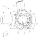
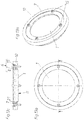
- Fig. 2c the holding device 3 together with clamped blank 1, 2 is shown in a 3D view. There are also the axes of rotation for the two retaining rings 10 and 11 can be seen.
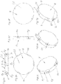
- Fig. 3a is in a side view of the substantially circular cylinder jacket-shaped peripheral surface U of a blank 1, 2 shown.
- this circular cylinder jacket-shaped peripheral surface U more recesses 4 are present. Through these recesses 4 are parallel to the front V and the back R main holding surfaces K 1 and auxiliary holding surfaces K 2 on the blank 1, 2 are formed.
- a part of the second side (corresponding to the rear side R) forms counter-holding surfaces G (see FIG Fig. 3g ).
- the main holding surfaces K 1 in the region of the recesses 4 and the rear side R are each spaced apart from each other by the standard holding thickness D 1 .
- the blank 1, 2 has the special holding thickness D 2 as a distance to the rear side R.
- the special holding thickness D 2 is smaller, preferably half as large as the standard holding thickness D 1 .
- the same components or surfaces are recognizable.
- the at least one positioning groove 16 can be seen, via which the blanks 1, 2 are clamped at a suitable location in the holding device 3. This also guarantees that when clamping two blanks 1, 2, the auxiliary holding surfaces K 2 of the two blanks 1, 2 correctly - that is axially opposite each other - to each other are positioned. Alternatively, it is also possible to realize a positioning via the position bores 19 formed in the rear side R.
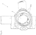
- Fig. 4a shows a holding device 3, which has an inner retaining ring 10, an outer retaining ring 11, a preferably C-shaped support 12 and two drive motors 13 and 14 for the two retaining rings 10 and 11.
- the inner retaining ring 10 are - as in Fig. 4b visible - the two blanks 1 and 2 used.
- the first blank 1 rests on the clamping surfaces 8 of the clamping device 6 via its auxiliary holding surfaces K 2 .
- the tensioning device 6 is formed by the clamping surfaces 8, the clamping parts 7 and the clamping bolt 15.
- the Fig. 4a and 4b are the clamping parts 7 still in the passive position P.
- the blanks 1, 2 according to the Fig. 6a to 6g be pre-processed or pre-milled.
- the blanks 1, 2 (blocks) are formed so that the remaining geometry of a denture modeled is. This has the advantage that it is no longer necessary to cut the complete block.
- the cutouts 17 thus no longer need to be incorporated by a device at the dental technician, but are already delivered with cutouts 17.
- the bit-shaped inner region of this blank 1, 2 is connected by connecting webs 18 with the outer region.
- Fig. 7a shows an assembly 5 with a holding device 3, two clamped in the holding device 3 blanks 1 and 2 and a processing device 9.
- This processing device 9 can, as in Fig. 7b shown to have a spindle.
- a milling cutter or the like may be arranged to machine the individual blanks 1 and 2 successively from the front side V, respectively.
- the inner retaining ring 10 can rotate at least by 180 °, preferably complete 360 °, about an axis. From this Fig. 7b is also clearly visible that in the clamped state, the entire front V of the blanks 1 and 2 is substantially completely accessible. As a result, unnecessary re-clamping is prevented and a complete working out of the dental elements E of two blanks 1 and 2 is feasible without intervening work by a dental technician would be necessary.
- the Fig. 8a and 8b show two blanks 1 and 2, wherein from the second blank 2 already only a schematically indicated dental element E is worked out. This dental element E is still connected via the webs 18 with the remaining area of the blank 2. In a later sequence, this dental element E is then removed from the second blank 2 by a dental technician or by special devices.
- Dental elements E can be, for example, crowns, bridges, or the like. Dental models are preferably produced from these blanks in order subsequently to perform teeth movement simulations. Also carrier models for dentures can be produced.
- the blanks 1 and 2 may, for example, zircon, metal, gypsum or plastic.
- the special holding thicknesses D 2 in the area of the auxiliary holding surfaces K 2 together give the standard holding thickness D 1 .
- Fig. 9a and 9b show two blanks 1 and 2, which abut each other over their respective rear side R.
- Such simple, cylindrical blanks 1 and 2 can be clamped in an arrangement according to the invention and processed over both substantially completely accessible front sides V.
- Fig. 11 a and 11 b show blanks 1 and 2, each with a continuous, peripheral gradation 21st
- Such gradation 21 is also in the blanks according to the Fig. 12a to 12c available.
- a tensioning device 6 In the Fig. 13a to 16c an alternative embodiment of a tensioning device 6 is shown. Thus, all these representations have in common that the tensioning device 6 has an annular, one-piece clamping part 7, a plurality of clamping bolts 15 in the form of screws and the (inner) retaining ring 10 formed clamping surfaces 8.
- Fig. 15c shows that the retaining ring 10 additionally has an intermediate piece 22 which forms the clamping surface 8.
- Fig. 16a to 16c are two blanks 1 and 2 clamped in such a holding device 3.
- a second, lower annular clamping part 7 is provided.
- a tensioning bolt 15 suitable internal thread may be formed in this lower clamping part 7.
- the lower clamping part 7 via two "coming from below” and from there screwed to the retaining ring 10 clamping bolt 15 with the retaining ring 10 is connectable.
- Fig. 16a is through the dashed lines indicated that more than two blanks 1 and 2 can be held in a holding device 3.
- two separate, spaced and smaller (in this case approximately semicircular) blanks 1 can be clamped in "one plane".
- the second blank 2 can be processed by the processing device 9 at least partially via its rear side R. This is also possible if previously a sufficient range was already released by processing the first blank 1, which allows access to the back R of the second blank 2.
Landscapes
- Health & Medical Sciences (AREA)
- Oral & Maxillofacial Surgery (AREA)
- Dentistry (AREA)
- Epidemiology (AREA)
- Life Sciences & Earth Sciences (AREA)
- Animal Behavior & Ethology (AREA)
- General Health & Medical Sciences (AREA)
- Public Health (AREA)
- Veterinary Medicine (AREA)
- Jigs For Machine Tools (AREA)
- Dental Prosthetics (AREA)
- Dental Tools And Instruments Or Auxiliary Dental Instruments (AREA)
Applications Claiming Priority (2)
| Application Number | Priority Date | Filing Date | Title |
|---|---|---|---|
| ATA50352/2015A AT516840B1 (de) | 2015-04-30 | 2015-04-30 | Rohling zur Herstellung eines Dentalelements |
| EP16164903.3A EP3095412B1 (fr) | 2015-04-30 | 2016-04-12 | Ébauche destinée à fabriquer une prothèse dentaire |
Related Parent Applications (2)
| Application Number | Title | Priority Date | Filing Date |
|---|---|---|---|
| EP16164903.3A Division EP3095412B1 (fr) | 2015-04-30 | 2016-04-12 | Ébauche destinée à fabriquer une prothèse dentaire |
| EP16164903.3A Division-Into EP3095412B1 (fr) | 2015-04-30 | 2016-04-12 | Ébauche destinée à fabriquer une prothèse dentaire |
Publications (2)
| Publication Number | Publication Date |
|---|---|
| EP3216420A1 true EP3216420A1 (fr) | 2017-09-13 |
| EP3216420B1 EP3216420B1 (fr) | 2018-12-05 |
Family
ID=55745668
Family Applications (2)
| Application Number | Title | Priority Date | Filing Date |
|---|---|---|---|
| EP17165754.7A Active EP3216420B1 (fr) | 2015-04-30 | 2016-04-12 | Ébauche destinée à fabriquer une prothèse dentaire |
| EP16164903.3A Active EP3095412B1 (fr) | 2015-04-30 | 2016-04-12 | Ébauche destinée à fabriquer une prothèse dentaire |
Family Applications After (1)
| Application Number | Title | Priority Date | Filing Date |
|---|---|---|---|
| EP16164903.3A Active EP3095412B1 (fr) | 2015-04-30 | 2016-04-12 | Ébauche destinée à fabriquer une prothèse dentaire |
Country Status (4)
| Country | Link |
|---|---|
| US (1) | US20160317258A1 (fr) |
| EP (2) | EP3216420B1 (fr) |
| AT (1) | AT516840B1 (fr) |
| ES (2) | ES2701129T3 (fr) |
Cited By (7)
| Publication number | Priority date | Publication date | Assignee | Title |
|---|---|---|---|---|
| EP3372192A1 (fr) * | 2017-03-10 | 2018-09-12 | Johannes Petrus Michael Grobbee | Dispositif de positionnement d'ébauche dentaire |
| US10905528B2 (en) | 2016-09-21 | 2021-02-02 | Global Dental Science, LLC | System and method for registering implant orientation directly from a dental impression |
| US10952829B2 (en) | 2016-11-27 | 2021-03-23 | Global Dental Science Llc | Tooth fixturing using machinable matrices |
| US11858083B2 (en) | 2017-03-09 | 2024-01-02 | Global Dental Science, LLC | Dental blank positioning device |
| US11986363B2 (en) | 2018-02-16 | 2024-05-21 | Global Dental Science, LLC | Real time anatomical adaptation |
| US12274599B2 (en) | 2017-08-16 | 2025-04-15 | Global Dental Science, LLC | Bar manufacturing and denture reference and registration system |
| US12558200B2 (en) | 2019-09-12 | 2026-02-24 | Heinrich Steger | Retaining device for a dental workpiece |
Families Citing this family (14)
| Publication number | Priority date | Publication date | Assignee | Title |
|---|---|---|---|---|
| US10905531B2 (en) | 2016-07-29 | 2021-02-02 | Shofu Inc. | Mill blank for dental CAD/CAM with groove not extending over whole of circumference |
| EP3284438B1 (fr) * | 2016-08-17 | 2020-10-07 | Shofu Inc. | Ébauche pour système cad/cam dentaire avec partie de découpe pour positionnement |
| AT519962B1 (de) * | 2017-06-13 | 2018-12-15 | Steger Heinrich | Bearbeitungsmaschine für die Herstellung von zahntechnischen Werkstücken |
| US10799326B2 (en) | 2017-08-08 | 2020-10-13 | Dentsply Sirona Inc. | Method for the positioning of a blank |
| EP3664744B1 (fr) * | 2017-08-08 | 2023-03-08 | Dentsply Sirona Inc. | Procédé pour le positionnement d'une ébauche |
| EP3681432B1 (fr) * | 2017-09-12 | 2024-07-31 | DeguDent GmbH | Ébauche et procédé de production d'au moins une pièce moulée |
| JP2019076416A (ja) * | 2017-10-25 | 2019-05-23 | Dgshape株式会社 | 歯科用技工物の加工方法 |
| EP3653169B1 (fr) * | 2018-11-15 | 2023-08-02 | SIRONA Dental Systems GmbH | Procédé de production de pièces de prothèse dentaire en céramique, station d'usinage cad/cam, et ébauche en céramique dentaire à résistance finale |
| EP3708114A1 (fr) * | 2019-03-11 | 2020-09-16 | DeguDent GmbH | Ébauche pour fraisage ou meulage d'un article dentaire |
| AT522091B1 (de) | 2019-03-21 | 2020-08-15 | Steger Heinrich | Verfahren zum Herstellen eines Zahnersatzes |
| JP7485328B2 (ja) * | 2019-12-03 | 2024-05-16 | 株式会社DentalBank | 歯科用被切削体 |
| DE202021002300U1 (de) | 2021-07-05 | 2021-08-30 | Zirkonzahn Gmbh | Vorrichtung zur Positionierung eines Dentalhalbzeuges |
| ES3026805T3 (en) * | 2022-05-19 | 2025-06-12 | Heinrich Steger | Dental blank and transport system, storage system or clamping device therefor |
| TWI817833B (zh) * | 2022-11-18 | 2023-10-01 | 遠東科技大學 | 載體保濕夾具裝置 |
Citations (8)
| Publication number | Priority date | Publication date | Assignee | Title |
|---|---|---|---|---|
| EP0480209A1 (fr) * | 1990-10-10 | 1992-04-15 | Mikrona Technologie Ag | Ebauche destinée à la fabrication d'une pièce dentaire et dispositif de préhension y associé |
| DE20316004U1 (de) | 2003-10-14 | 2004-03-04 | Stührenberg, Birgit | Rohling für die Herstellung von Zahnersatz |
| US20090130634A1 (en) * | 2007-07-20 | 2009-05-21 | Ivoclar Vivadent Ag | Addressable matrices/cluster blanks for dental cad/cam systems and optimization thereof |
| WO2010094922A1 (fr) | 2009-02-19 | 2010-08-26 | Renishaw Plc | Billette et support de billette correspondant |
| EP2462894A2 (fr) | 2010-12-08 | 2012-06-13 | Helge Arndt | Procédé de fabrication de pièces dentaires |
| DE102011055393A1 (de) * | 2011-11-15 | 2013-05-16 | Ralph Gerschütz-Rüth | Rohling für künstliche Zähne mit mehreren unterschiedlichen Farbschichten und Verfahren zu dessen Herstellung |
| WO2013072287A1 (fr) | 2011-11-15 | 2013-05-23 | Kronacher Werkzeugbau Klug Gmbh & Co. Kg | Ébauche de dent artificielle présentant plusieurs couches de couleurs différentes et son procédé de fabrication |
| WO2013122662A1 (fr) | 2012-02-13 | 2013-08-22 | 3M Innovative Properties Company | Bloc de rodage dentaire contenant un article dentaire individualisé et procédé de fabrication |
-
2015
- 2015-04-30 AT ATA50352/2015A patent/AT516840B1/de active
-
2016
- 2016-04-12 ES ES16164903T patent/ES2701129T3/es active Active
- 2016-04-12 EP EP17165754.7A patent/EP3216420B1/fr active Active
- 2016-04-12 ES ES17165754T patent/ES2714729T3/es active Active
- 2016-04-12 EP EP16164903.3A patent/EP3095412B1/fr active Active
- 2016-04-27 US US15/139,498 patent/US20160317258A1/en not_active Abandoned
Patent Citations (9)
| Publication number | Priority date | Publication date | Assignee | Title |
|---|---|---|---|---|
| EP0480209A1 (fr) * | 1990-10-10 | 1992-04-15 | Mikrona Technologie Ag | Ebauche destinée à la fabrication d'une pièce dentaire et dispositif de préhension y associé |
| DE20316004U1 (de) | 2003-10-14 | 2004-03-04 | Stührenberg, Birgit | Rohling für die Herstellung von Zahnersatz |
| US20090130634A1 (en) * | 2007-07-20 | 2009-05-21 | Ivoclar Vivadent Ag | Addressable matrices/cluster blanks for dental cad/cam systems and optimization thereof |
| WO2010094922A1 (fr) | 2009-02-19 | 2010-08-26 | Renishaw Plc | Billette et support de billette correspondant |
| EP2462894A2 (fr) | 2010-12-08 | 2012-06-13 | Helge Arndt | Procédé de fabrication de pièces dentaires |
| DE102010061116A1 (de) | 2010-12-08 | 2012-06-14 | Helge Arndt | Verfahren zur Herstellung von dentalen Werkstücken |
| DE102011055393A1 (de) * | 2011-11-15 | 2013-05-16 | Ralph Gerschütz-Rüth | Rohling für künstliche Zähne mit mehreren unterschiedlichen Farbschichten und Verfahren zu dessen Herstellung |
| WO2013072287A1 (fr) | 2011-11-15 | 2013-05-23 | Kronacher Werkzeugbau Klug Gmbh & Co. Kg | Ébauche de dent artificielle présentant plusieurs couches de couleurs différentes et son procédé de fabrication |
| WO2013122662A1 (fr) | 2012-02-13 | 2013-08-22 | 3M Innovative Properties Company | Bloc de rodage dentaire contenant un article dentaire individualisé et procédé de fabrication |
Cited By (7)
| Publication number | Priority date | Publication date | Assignee | Title |
|---|---|---|---|---|
| US10905528B2 (en) | 2016-09-21 | 2021-02-02 | Global Dental Science, LLC | System and method for registering implant orientation directly from a dental impression |
| US10952829B2 (en) | 2016-11-27 | 2021-03-23 | Global Dental Science Llc | Tooth fixturing using machinable matrices |
| US11858083B2 (en) | 2017-03-09 | 2024-01-02 | Global Dental Science, LLC | Dental blank positioning device |
| EP3372192A1 (fr) * | 2017-03-10 | 2018-09-12 | Johannes Petrus Michael Grobbee | Dispositif de positionnement d'ébauche dentaire |
| US12274599B2 (en) | 2017-08-16 | 2025-04-15 | Global Dental Science, LLC | Bar manufacturing and denture reference and registration system |
| US11986363B2 (en) | 2018-02-16 | 2024-05-21 | Global Dental Science, LLC | Real time anatomical adaptation |
| US12558200B2 (en) | 2019-09-12 | 2026-02-24 | Heinrich Steger | Retaining device for a dental workpiece |
Also Published As
| Publication number | Publication date |
|---|---|
| EP3095412A3 (fr) | 2017-02-22 |
| AT516840B1 (de) | 2016-09-15 |
| EP3095412B1 (fr) | 2018-09-05 |
| US20160317258A1 (en) | 2016-11-03 |
| EP3216420B1 (fr) | 2018-12-05 |
| ES2714729T3 (es) | 2019-05-29 |
| ES2701129T3 (es) | 2019-02-20 |
| EP3095412A2 (fr) | 2016-11-23 |
| AT516840A4 (de) | 2016-09-15 |
Similar Documents
| Publication | Publication Date | Title |
|---|---|---|
| EP3216420B1 (fr) | Ébauche destinée à fabriquer une prothèse dentaire | |
| EP2029305B1 (fr) | Outil d'usinage et anneau de coupe pour un outil d'usinage | |
| DE102014000664B3 (de) | Werkstückträger für eine Fräsmaschine | |
| DE102004026601A1 (de) | Wendeschneideinsatz zum Drehen | |
| DE102016124892B4 (de) | Bearbeitungsvorrichtung mit einer programmtechnischen Steuerung | |
| DE202007018838U1 (de) | Werkzeugmaschine und Bearbeitungswerkzeug für eine Werkzeugmaschine | |
| DE19548978C2 (de) | Spannvorrichtung zum Halten von Werkstücken | |
| DE3130229C2 (de) | Mehrschneidenwerkzeug | |
| EP1752253A1 (fr) | Dispositif de serrage et procédé pour usiner des pièces à travailler serrées sur un tel dispositif de serrage | |
| WO2020178439A1 (fr) | Dispositif de fixation d'une ébauche dentaire à une machine d'usinage | |
| DE2848230A1 (de) | Aufbohrwerkzeug | |
| EP4374817B1 (fr) | Pièce de traitement dentaire | |
| LU102049B1 (de) | Modular aufgebaute spannvorrichtung zur aufnahme von profil-schliesszylinder zur gravur | |
| DE19854214C1 (de) | Elementsystem | |
| DE102013003771A1 (de) | Verzahnmaschine zum Bearbeiten eines Werkstücks und Vefahren zum Bearbeiten einer Kurbelwelle | |
| DE9309505U1 (de) | Vorrichtung zur spanabhebenden herstellung von profilen, insbesondere von polygonprofilen | |
| DE2626155A1 (de) | Vorrichtung zum hochpraezisen aufspannen von werkstuecken | |
| DE19726923C1 (de) | Verfahren zum fugenschlüssigen Verbinden von Holzteilen | |
| DE933844C (de) | Vorrichtung zum Bohren und Drehen | |
| DE9204892U1 (de) | Vorrichtung zum Einspannen von Werkstücken o.dgl. | |
| EP3479936A1 (fr) | Tournage de pièces à usiner sur une machine-outil | |
| DE102013002815A1 (de) | Vorrichtung zur spanabhebenden Bearbeitung | |
| DE9015547U1 (de) | Zirkularfräser mit einem zylindrischen Fräserschaft und auswechselbar befestigter Schneidplatte | |
| DE102012015980A1 (de) | Verfahren zur Herstellung eines Schneidmesser- oder Abkantmoduls, Schneidmesser- oder Abkantmodul und Presswerkzeug | |
| DE1175720B (de) | Verfahren zur Bearbeitung der Achslager-fuehrungsflaechen an einem Lokomotivrahmen |
Legal Events
| Date | Code | Title | Description |
|---|---|---|---|
| PUAI | Public reference made under article 153(3) epc to a published international application that has entered the european phase |
Free format text: ORIGINAL CODE: 0009012 |
|
| STAA | Information on the status of an ep patent application or granted ep patent |
Free format text: STATUS: THE APPLICATION HAS BEEN PUBLISHED |
|
| AC | Divisional application: reference to earlier application |
Ref document number: 3095412 Country of ref document: EP Kind code of ref document: P |
|
| AK | Designated contracting states |
Kind code of ref document: A1 Designated state(s): AL AT BE BG CH CY CZ DE DK EE ES FI FR GB GR HR HU IE IS IT LI LT LU LV MC MK MT NL NO PL PT RO RS SE SI SK SM TR |
|
| AX | Request for extension of the european patent |
Extension state: BA ME |
|
| STAA | Information on the status of an ep patent application or granted ep patent |
Free format text: STATUS: REQUEST FOR EXAMINATION WAS MADE |
|
| 17P | Request for examination filed |
Effective date: 20171006 |
|
| RBV | Designated contracting states (corrected) |
Designated state(s): AL AT BE BG CH CY CZ DE DK EE ES FI FR GB GR HR HU IE IS IT LI LT LU LV MC MK MT NL NO PL PT RO RS SE SI SK SM TR |
|
| GRAP | Despatch of communication of intention to grant a patent |
Free format text: ORIGINAL CODE: EPIDOSNIGR1 |
|
| STAA | Information on the status of an ep patent application or granted ep patent |
Free format text: STATUS: GRANT OF PATENT IS INTENDED |
|
| INTG | Intention to grant announced |
Effective date: 20180824 |
|
| GRAS | Grant fee paid |
Free format text: ORIGINAL CODE: EPIDOSNIGR3 |
|
| GRAA | (expected) grant |
Free format text: ORIGINAL CODE: 0009210 |
|
| STAA | Information on the status of an ep patent application or granted ep patent |
Free format text: STATUS: THE PATENT HAS BEEN GRANTED |
|
| AC | Divisional application: reference to earlier application |
Ref document number: 3095412 Country of ref document: EP Kind code of ref document: P |
|
| AK | Designated contracting states |
Kind code of ref document: B1 Designated state(s): AL AT BE BG CH CY CZ DE DK EE ES FI FR GB GR HR HU IE IS IT LI LT LU LV MC MK MT NL NO PL PT RO RS SE SI SK SM TR |
|
| REG | Reference to a national code |
Ref country code: GB Ref legal event code: FG4D Free format text: NOT ENGLISH |
|
| REG | Reference to a national code |
Ref country code: CH Ref legal event code: EP |
|
| REG | Reference to a national code |
Ref country code: AT Ref legal event code: REF Ref document number: 1072112 Country of ref document: AT Kind code of ref document: T Effective date: 20181215 |
|
| REG | Reference to a national code |
Ref country code: IE Ref legal event code: FG4D Free format text: LANGUAGE OF EP DOCUMENT: GERMAN |
|
| REG | Reference to a national code |
Ref country code: DE Ref legal event code: R096 Ref document number: 502016002728 Country of ref document: DE |
|
| REG | Reference to a national code |
Ref country code: NL Ref legal event code: MP Effective date: 20181205 |
|
| REG | Reference to a national code |
Ref country code: LT Ref legal event code: MG4D |
|
| PG25 | Lapsed in a contracting state [announced via postgrant information from national office to epo] |
Ref country code: FI Free format text: LAPSE BECAUSE OF FAILURE TO SUBMIT A TRANSLATION OF THE DESCRIPTION OR TO PAY THE FEE WITHIN THE PRESCRIBED TIME-LIMIT Effective date: 20181205 Ref country code: LV Free format text: LAPSE BECAUSE OF FAILURE TO SUBMIT A TRANSLATION OF THE DESCRIPTION OR TO PAY THE FEE WITHIN THE PRESCRIBED TIME-LIMIT Effective date: 20181205 Ref country code: NO Free format text: LAPSE BECAUSE OF FAILURE TO SUBMIT A TRANSLATION OF THE DESCRIPTION OR TO PAY THE FEE WITHIN THE PRESCRIBED TIME-LIMIT Effective date: 20190305 Ref country code: BG Free format text: LAPSE BECAUSE OF FAILURE TO SUBMIT A TRANSLATION OF THE DESCRIPTION OR TO PAY THE FEE WITHIN THE PRESCRIBED TIME-LIMIT Effective date: 20190305 Ref country code: LT Free format text: LAPSE BECAUSE OF FAILURE TO SUBMIT A TRANSLATION OF THE DESCRIPTION OR TO PAY THE FEE WITHIN THE PRESCRIBED TIME-LIMIT Effective date: 20181205 Ref country code: HR Free format text: LAPSE BECAUSE OF FAILURE TO SUBMIT A TRANSLATION OF THE DESCRIPTION OR TO PAY THE FEE WITHIN THE PRESCRIBED TIME-LIMIT Effective date: 20181205 |
|
| REG | Reference to a national code |
Ref country code: ES Ref legal event code: FG2A Ref document number: 2714729 Country of ref document: ES Kind code of ref document: T3 Effective date: 20190529 |
|
| PG25 | Lapsed in a contracting state [announced via postgrant information from national office to epo] |
Ref country code: AL Free format text: LAPSE BECAUSE OF FAILURE TO SUBMIT A TRANSLATION OF THE DESCRIPTION OR TO PAY THE FEE WITHIN THE PRESCRIBED TIME-LIMIT Effective date: 20181205 Ref country code: SE Free format text: LAPSE BECAUSE OF FAILURE TO SUBMIT A TRANSLATION OF THE DESCRIPTION OR TO PAY THE FEE WITHIN THE PRESCRIBED TIME-LIMIT Effective date: 20181205 Ref country code: GR Free format text: LAPSE BECAUSE OF FAILURE TO SUBMIT A TRANSLATION OF THE DESCRIPTION OR TO PAY THE FEE WITHIN THE PRESCRIBED TIME-LIMIT Effective date: 20190306 Ref country code: RS Free format text: LAPSE BECAUSE OF FAILURE TO SUBMIT A TRANSLATION OF THE DESCRIPTION OR TO PAY THE FEE WITHIN THE PRESCRIBED TIME-LIMIT Effective date: 20181205 |
|
| PG25 | Lapsed in a contracting state [announced via postgrant information from national office to epo] |
Ref country code: NL Free format text: LAPSE BECAUSE OF FAILURE TO SUBMIT A TRANSLATION OF THE DESCRIPTION OR TO PAY THE FEE WITHIN THE PRESCRIBED TIME-LIMIT Effective date: 20181205 |
|
| PG25 | Lapsed in a contracting state [announced via postgrant information from national office to epo] |
Ref country code: CZ Free format text: LAPSE BECAUSE OF FAILURE TO SUBMIT A TRANSLATION OF THE DESCRIPTION OR TO PAY THE FEE WITHIN THE PRESCRIBED TIME-LIMIT Effective date: 20181205 Ref country code: PT Free format text: LAPSE BECAUSE OF FAILURE TO SUBMIT A TRANSLATION OF THE DESCRIPTION OR TO PAY THE FEE WITHIN THE PRESCRIBED TIME-LIMIT Effective date: 20190405 Ref country code: PL Free format text: LAPSE BECAUSE OF FAILURE TO SUBMIT A TRANSLATION OF THE DESCRIPTION OR TO PAY THE FEE WITHIN THE PRESCRIBED TIME-LIMIT Effective date: 20181205 |
|
| PG25 | Lapsed in a contracting state [announced via postgrant information from national office to epo] |
Ref country code: IS Free format text: LAPSE BECAUSE OF FAILURE TO SUBMIT A TRANSLATION OF THE DESCRIPTION OR TO PAY THE FEE WITHIN THE PRESCRIBED TIME-LIMIT Effective date: 20190405 Ref country code: EE Free format text: LAPSE BECAUSE OF FAILURE TO SUBMIT A TRANSLATION OF THE DESCRIPTION OR TO PAY THE FEE WITHIN THE PRESCRIBED TIME-LIMIT Effective date: 20181205 Ref country code: SM Free format text: LAPSE BECAUSE OF FAILURE TO SUBMIT A TRANSLATION OF THE DESCRIPTION OR TO PAY THE FEE WITHIN THE PRESCRIBED TIME-LIMIT Effective date: 20181205 Ref country code: RO Free format text: LAPSE BECAUSE OF FAILURE TO SUBMIT A TRANSLATION OF THE DESCRIPTION OR TO PAY THE FEE WITHIN THE PRESCRIBED TIME-LIMIT Effective date: 20181205 Ref country code: SK Free format text: LAPSE BECAUSE OF FAILURE TO SUBMIT A TRANSLATION OF THE DESCRIPTION OR TO PAY THE FEE WITHIN THE PRESCRIBED TIME-LIMIT Effective date: 20181205 |
|
| REG | Reference to a national code |
Ref country code: DE Ref legal event code: R097 Ref document number: 502016002728 Country of ref document: DE |
|
| PLBE | No opposition filed within time limit |
Free format text: ORIGINAL CODE: 0009261 |
|
| STAA | Information on the status of an ep patent application or granted ep patent |
Free format text: STATUS: NO OPPOSITION FILED WITHIN TIME LIMIT |
|
| PG25 | Lapsed in a contracting state [announced via postgrant information from national office to epo] |
Ref country code: DK Free format text: LAPSE BECAUSE OF FAILURE TO SUBMIT A TRANSLATION OF THE DESCRIPTION OR TO PAY THE FEE WITHIN THE PRESCRIBED TIME-LIMIT Effective date: 20181205 Ref country code: SI Free format text: LAPSE BECAUSE OF FAILURE TO SUBMIT A TRANSLATION OF THE DESCRIPTION OR TO PAY THE FEE WITHIN THE PRESCRIBED TIME-LIMIT Effective date: 20181205 |
|
| 26N | No opposition filed |
Effective date: 20190906 |
|
| REG | Reference to a national code |
Ref country code: CH Ref legal event code: PL |
|
| REG | Reference to a national code |
Ref country code: BE Ref legal event code: MM Effective date: 20190430 |
|
| PG25 | Lapsed in a contracting state [announced via postgrant information from national office to epo] |
Ref country code: LU Free format text: LAPSE BECAUSE OF NON-PAYMENT OF DUE FEES Effective date: 20190412 Ref country code: MC Free format text: LAPSE BECAUSE OF FAILURE TO SUBMIT A TRANSLATION OF THE DESCRIPTION OR TO PAY THE FEE WITHIN THE PRESCRIBED TIME-LIMIT Effective date: 20181205 |
|
| PG25 | Lapsed in a contracting state [announced via postgrant information from national office to epo] |
Ref country code: LI Free format text: LAPSE BECAUSE OF NON-PAYMENT OF DUE FEES Effective date: 20190430 Ref country code: CH Free format text: LAPSE BECAUSE OF NON-PAYMENT OF DUE FEES Effective date: 20190430 |
|
| PG25 | Lapsed in a contracting state [announced via postgrant information from national office to epo] |
Ref country code: BE Free format text: LAPSE BECAUSE OF NON-PAYMENT OF DUE FEES Effective date: 20190430 |
|
| PG25 | Lapsed in a contracting state [announced via postgrant information from national office to epo] |
Ref country code: TR Free format text: LAPSE BECAUSE OF FAILURE TO SUBMIT A TRANSLATION OF THE DESCRIPTION OR TO PAY THE FEE WITHIN THE PRESCRIBED TIME-LIMIT Effective date: 20181205 |
|
| PG25 | Lapsed in a contracting state [announced via postgrant information from national office to epo] |
Ref country code: IE Free format text: LAPSE BECAUSE OF NON-PAYMENT OF DUE FEES Effective date: 20190412 |
|
| GBPC | Gb: european patent ceased through non-payment of renewal fee |
Effective date: 20200412 |
|
| PG25 | Lapsed in a contracting state [announced via postgrant information from national office to epo] |
Ref country code: GB Free format text: LAPSE BECAUSE OF NON-PAYMENT OF DUE FEES Effective date: 20200412 |
|
| PG25 | Lapsed in a contracting state [announced via postgrant information from national office to epo] |
Ref country code: CY Free format text: LAPSE BECAUSE OF FAILURE TO SUBMIT A TRANSLATION OF THE DESCRIPTION OR TO PAY THE FEE WITHIN THE PRESCRIBED TIME-LIMIT Effective date: 20181205 |
|
| PG25 | Lapsed in a contracting state [announced via postgrant information from national office to epo] |
Ref country code: MT Free format text: LAPSE BECAUSE OF FAILURE TO SUBMIT A TRANSLATION OF THE DESCRIPTION OR TO PAY THE FEE WITHIN THE PRESCRIBED TIME-LIMIT Effective date: 20181205 Ref country code: HU Free format text: LAPSE BECAUSE OF FAILURE TO SUBMIT A TRANSLATION OF THE DESCRIPTION OR TO PAY THE FEE WITHIN THE PRESCRIBED TIME-LIMIT; INVALID AB INITIO Effective date: 20160412 |
|
| PG25 | Lapsed in a contracting state [announced via postgrant information from national office to epo] |
Ref country code: MK Free format text: LAPSE BECAUSE OF FAILURE TO SUBMIT A TRANSLATION OF THE DESCRIPTION OR TO PAY THE FEE WITHIN THE PRESCRIBED TIME-LIMIT Effective date: 20181205 |
|
| PGFP | Annual fee paid to national office [announced via postgrant information from national office to epo] |
Ref country code: FR Payment date: 20250320 Year of fee payment: 10 |
|
| PGFP | Annual fee paid to national office [announced via postgrant information from national office to epo] |
Ref country code: DE Payment date: 20250325 Year of fee payment: 10 |
|
| PGFP | Annual fee paid to national office [announced via postgrant information from national office to epo] |
Ref country code: ES Payment date: 20250512 Year of fee payment: 10 |
|
| PGFP | Annual fee paid to national office [announced via postgrant information from national office to epo] |
Ref country code: IT Payment date: 20250428 Year of fee payment: 10 |
|
| PGFP | Annual fee paid to national office [announced via postgrant information from national office to epo] |
Ref country code: AT Payment date: 20250428 Year of fee payment: 10 |