EP2463097A2 - Habillage de spot à l'aide d'un film - Google Patents
Habillage de spot à l'aide d'un film Download PDFInfo
- Publication number
- EP2463097A2 EP2463097A2 EP11188438A EP11188438A EP2463097A2 EP 2463097 A2 EP2463097 A2 EP 2463097A2 EP 11188438 A EP11188438 A EP 11188438A EP 11188438 A EP11188438 A EP 11188438A EP 2463097 A2 EP2463097 A2 EP 2463097A2
- Authority
- EP
- European Patent Office
- Prior art keywords
- laminating
- film
- substrate
- unit
- cutting
- Prior art date
- Legal status (The legal status is an assumption and is not a legal conclusion. Google has not performed a legal analysis and makes no representation as to the accuracy of the status listed.)
- Granted
Links
- 238000003475 lamination Methods 0.000 title claims abstract description 36
- 238000010030 laminating Methods 0.000 claims abstract description 192
- 239000002131 composite material Substances 0.000 claims abstract description 47
- 239000000758 substrate Substances 0.000 claims abstract description 42
- 238000000034 method Methods 0.000 claims abstract description 15
- 239000000853 adhesive Substances 0.000 claims description 34
- 230000001070 adhesive effect Effects 0.000 claims description 34
- 239000011248 coating agent Substances 0.000 claims description 17
- 238000000576 coating method Methods 0.000 claims description 17
- 239000012790 adhesive layer Substances 0.000 claims description 10
- 239000011888 foil Substances 0.000 claims description 8
- 238000011144 upstream manufacturing Methods 0.000 claims description 8
- 238000000926 separation method Methods 0.000 abstract 1
- 239000010410 layer Substances 0.000 description 14
- 238000001035 drying Methods 0.000 description 8
- 239000000463 material Substances 0.000 description 7
- 239000003973 paint Substances 0.000 description 6
- 239000000976 ink Substances 0.000 description 5
- 239000004922 lacquer Substances 0.000 description 5
- 230000004913 activation Effects 0.000 description 2
- 230000006378 damage Effects 0.000 description 2
- 230000002411 adverse Effects 0.000 description 1
- 238000007774 anilox coating Methods 0.000 description 1
- 230000005540 biological transmission Effects 0.000 description 1
- 230000006735 deficit Effects 0.000 description 1
- 239000007888 film coating Substances 0.000 description 1
- 238000009501 film coating Methods 0.000 description 1
- 238000010438 heat treatment Methods 0.000 description 1
- 230000011218 segmentation Effects 0.000 description 1
- 239000002966 varnish Substances 0.000 description 1
Images


Classifications
-
- B—PERFORMING OPERATIONS; TRANSPORTING
- B32—LAYERED PRODUCTS
- B32B—LAYERED PRODUCTS, i.e. PRODUCTS BUILT-UP OF STRATA OF FLAT OR NON-FLAT, e.g. CELLULAR OR HONEYCOMB, FORM
- B32B37/00—Methods or apparatus for laminating, e.g. by curing or by ultrasonic bonding
- B32B37/02—Methods or apparatus for laminating, e.g. by curing or by ultrasonic bonding characterised by a sequence of laminating steps, e.g. by adding new layers at consecutive laminating stations
- B32B37/025—Transfer laminating
-
- B—PERFORMING OPERATIONS; TRANSPORTING
- B32—LAYERED PRODUCTS
- B32B—LAYERED PRODUCTS, i.e. PRODUCTS BUILT-UP OF STRATA OF FLAT OR NON-FLAT, e.g. CELLULAR OR HONEYCOMB, FORM
- B32B37/00—Methods or apparatus for laminating, e.g. by curing or by ultrasonic bonding
- B32B37/12—Methods or apparatus for laminating, e.g. by curing or by ultrasonic bonding characterised by using adhesives
- B32B37/1284—Application of adhesive
-
- B—PERFORMING OPERATIONS; TRANSPORTING
- B32—LAYERED PRODUCTS
- B32B—LAYERED PRODUCTS, i.e. PRODUCTS BUILT-UP OF STRATA OF FLAT OR NON-FLAT, e.g. CELLULAR OR HONEYCOMB, FORM
- B32B38/00—Ancillary operations in connection with laminating processes
- B32B38/0004—Cutting, tearing or severing, e.g. bursting; Cutter details
-
- B—PERFORMING OPERATIONS; TRANSPORTING
- B41—PRINTING; LINING MACHINES; TYPEWRITERS; STAMPS
- B41F—PRINTING MACHINES OR PRESSES
- B41F19/00—Apparatus or machines for carrying out printing operations combined with other operations
- B41F19/001—Apparatus or machines for carrying out printing operations combined with other operations with means for coating or laminating
-
- B—PERFORMING OPERATIONS; TRANSPORTING
- B41—PRINTING; LINING MACHINES; TYPEWRITERS; STAMPS
- B41F—PRINTING MACHINES OR PRESSES
- B41F19/00—Apparatus or machines for carrying out printing operations combined with other operations
- B41F19/008—Apparatus or machines for carrying out printing operations combined with other operations with means for stamping or cutting out
-
- B—PERFORMING OPERATIONS; TRANSPORTING
- B44—DECORATIVE ARTS
- B44C—PRODUCING DECORATIVE EFFECTS; MOSAICS; TARSIA WORK; PAPERHANGING
- B44C1/00—Processes, not specifically provided for elsewhere, for producing decorative surface effects
- B44C1/10—Applying flat materials, e.g. leaflets, pieces of fabrics
- B44C1/105—Applying flat materials, e.g. leaflets, pieces of fabrics comprising an adhesive layer
-
- B—PERFORMING OPERATIONS; TRANSPORTING
- B41—PRINTING; LINING MACHINES; TYPEWRITERS; STAMPS
- B41M—PRINTING, DUPLICATING, MARKING, OR COPYING PROCESSES; COLOUR PRINTING
- B41M7/00—After-treatment of prints, e.g. heating, irradiating, setting of the ink, protection of the printed stock
- B41M7/0027—After-treatment of prints, e.g. heating, irradiating, setting of the ink, protection of the printed stock using protective coatings or layers by lamination or by fusion of the coatings or layers
Definitions
- the present invention relates to a method, a device and a composite film for use in a corresponding method for laminating substrate, wherein the substrate is fed to a lamination, the lamination comprises at least one lamination cylinder and a counter-pressure cylinder, which together form a lamination, the laminating a Laminierfolie is supplied, which is guided together with the substrate through the lamination and wherein in the lamination, the laminating film is transferred under pressure to the substrate.
- substrates such.
- the object of the present invention is therefore to reduce the disadvantages mentioned at least or to present a more flexible method and a corresponding device, which allow a corresponding protection and / or higher gloss for a printing material or a printed product.
- This object of the invention is achieved according to a method according to claim 1, a device according to claim 5 and independently by a composite film according to claim 10.
- the inventive method is characterized in that the laminating film is not provided as a stand-alone consumable material, but on a carrier film.
- the laminating film together with the carrier film then forms a composite film which is provided on a supply roll.
- a release and / or adhesive layer can be provided in particular between the laminating film and the carrier film. At least the detachment of the laminating film from the carrier film for transfer to a substrate or printing material can at least be supported by a separating layer.
- an optionally provided adhesive layer between the laminating film and the carrier film may favor the adhesion behavior of the laminating film to the carrier film prior to lamination of the printing material.
- the composite film consisting of the laminating film and the carrier film is transported through a laminating gap.
- This laminating gap is formed by a laminating cylinder and an impression cylinder.
- the laminating film is at least partially separated from the carrier film and transferred to the surface of the substrate.
- the used composite foil, which at least partially consists only of the carrier film is then fed to a film collecting roll.
- an adhesive layer is applied or applied to the surface of the substrate and / or the laminating film.
- a commissioned work for applying adhesive to the substrate and / or the laminating film may be arranged upstream of the laminating gap.
- Such a Vor elbow a commissioned work can z.
- Example consist in that on the same impression cylinder to which the lamination is employed, an application cylinder of the commissioned work is provided so that immediately before the substrate is transported into the lamination, this is acted upon with adhesive.
- it may also be a commissioning unit assigned correspondingly to the laminating cylinder, which provides for the adhesive application to the laminating film analogously.
- the commissioned work is separated from the lamination and this upstream upstream.
- the laminating unit may have at least one supply and / or collecting roller for providing or for receiving the composite film.
- a flexible embodiment of the lamination unit which as a whole is provided on a modular basis from a base unit and a lamination module, consisting of supply and / or collecting roller, is provided.
- a crosslinked stable self-supporting film is used as the laminating film.
- Such a self-supporting, stable and crosslinked film in contrast to powdery or granular layers can be made much more stable.
- a corresponding thickness of the film can be ensured, which forms an intended protection for the printing material.
- a cutting device is provided for cutting the laminating film between the supply roll and the laminating gap.
- this cutting device transverse and / or longitudinal cuts in the laminating film can be made possible.
- individual can Regions of the laminating film on the support film are cut or isolated so that they can be transferred alone to the substrate, if a corresponding adhesive coating is provided on this cut-out area or on the corresponding region of the substrate.
- this cutting device exclusively cuts into or interrupts the laminating film without damaging the carrier film itself.
- a drive unit for controlling the cutting device can advantageously be provided. This receives information about the nature and / or the thickness of the laminating film. In this way, it can control the cutting device and determine the cutting depth of the cutting device so that a function of the nature and or thickness of the laminating film, the cutting by the cutting device is performed so that the laminating film is cut without the support film itself by cutting is damaged.
- the drive unit may obtain data about the format and position of the areas to be laminated.
- the drive unit controls the cutting device or devices in accordance with this data in order to format-and position-dependently cut the laminating film to be transferred to the substrate.
- the device for laminating substrate is a printing machine, in particular a sheet-fed printing machine.
- a substrate can then be processed very flexible.
- the laminating unit within the printing machine at least one printing, cold foil or coating unit for coating the substrate before and / or is arranged downstream.
- So z. B. in one pass inline a substrate to be printed with a printed image, which is then immediately laminated in the laminating.
- it can be provided, in particular, to use UV inks and UV adhesives in order to ensure the fastest possible drying and activation of ink and / or adhesive by means of a UV drying device provided.
- printing or film coating may be provided on the laminated surface itself.
- the lamination itself is a printing or coating unit of the printing press.
- the lamination is a blanket cylinder of a printing unit or a forme cylinder of a coating unit or other coating plant.
- For applying the adhesive layer may then be provided in particular a pre-laminating the upstream printing or coating unit of the printing press.
- this commissioned work can also be employed on the impression cylinder of the lamination, as described above, independently.
- FIG. 1 shows a section of a laminating device 1 with a commissioned work 2 and a laminating 3.
- a sheet 4 is transported as a substrate in the direction 5 therethrough.
- the sheet 4 is first passed through a pressure nip 6, in which an adhesive at least in the areas on the sheet 4th is applied, in which then a laminating film 41 is to be applied.
- the printing nip 6 is formed by a counter-pressure cylinder 8 and a blanket cylinder 7, which acts here as a job cylinder.
- About a plate cylinder and an employee of this inking can be transferred in areas of the sheet 4 on the commissioned work 2 as in a conventional inking unit of a printing press, an adhesive instead of paint.
- the thus applied with adhesive sheet 4 is further transported by the laminating device 1 via a transfer cylinder 9 in the lamination 3.
- the sheet 4 is passed through a laminating gap 12.
- the laminating gap 12 is formed from a counter-pressure cylinder 8 and a laminating cylinder 19.
- the lamination cylinder 19 may in particular be a conventional blanket cylinder of a printing unit.
- the laminating unit 3 can be a conventional printing unit of a printing press.
- a composite film 10 is simultaneously passed through the laminating gap 12.
- the composite film 10 is transported in the direction of the arrow 11 so that its transport direction in the lamination 12 corresponds to the direction of movement of the sheet 4.
- the composite film 10 is withdrawn from a supply roll 14 and guided over deflecting rollers 13 to the laminating gap 12.
- the composite film 10 is guided further over deflecting rollers 13 to a collecting roller 15.
- the composite foil 10 is, as in FIG. 4 More specifically, constructed from a carrier film 40, a release layer 42 and a laminating film 41.
- the laminating film 41 is applied over the entire surface of the carrier film 40 and provides a networked, stable, self-supporting film. Without further precautions would by the applied adhesive in the commissioned work 2, the entire laminating 41 without stopping on the sheet 4 and further following sheet. 4 be transmitted.
- a cutter 17 is provided in order to allow a region-wise transmission of the laminating film 41 on a sheet 4, between the supply roll 14 and the laminating nip 12, a cutter 17 is provided.
- This cutting device 17 is controlled by a drive unit 18 so that, depending on the desired position and the desired format of the laminated surface on the sheet 4, the lamination or the laminating film 41 is cut on the carrier film so that just such segments from the Remove the laminate of the laminating film 41, which correspond to the desired format.
- an adhesive layer which corresponds exactly to the format and the position of the desired laminated areas, in the commissioned work 2 on the blanket cylinder 7 is transferred to the sheet 4.
- a pressure plate is advantageously clamped on the printing plate cylinder 16, which is so exposed that the areas corresponding to the areas to be laminated on the sheet 4, color or adhesive are.
- an adhesive is to be understood in particular an adhesive color, which may be both colored and colorless.
- FIG. 2 is shown as an alternative possibility that an adhesive can be applied from an adhesive reservoir 23 via an applicator roll 22 directly to the surface of the laminating film 41 of the composite film 10.
- a commissioned work 21 is arranged in the direction of movement of the composite film 10 in the direction of movement 11 of the composite film 10 in front of the laminating gap 12.
- a deflection roller 13 can act in particular as a counter-roller to the application roller 22, so that the adhesive can be applied cleanly to the surface of the laminating film 41.
- only the region of the laminating unit 20 which lies directly in the vicinity of the laminating gap 12 is shown in this figure.
- the application roller 22 may be designed so that adhesive is always applied from the adhesive reservoir 23 to the surface of the laminating film 41 over the whole area. By appropriate cross-sections in the laminating film 41, a full-surface lamination of the sheet 4 can then be ensured.
- the application roller 22 is an anilox roller, wherein the raster distribution on the surface is designed so that the adhesive is only partially transferred in desired areas.
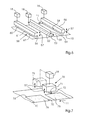
- FIG. 3 shows a corresponding alternative application option for an adhesive.
- a commissioned work 31 is employed directly to the impression cylinder 8, so that an adhesive from an adhesive reservoir 33 via an applicator roll 32 on a sheet 4, which is transported on the impression cylinder 8, can be applied.
- the laminating gap 12 then follows immediately behind the applicator 31 on the same impression cylinder. 8
- FIG. 4 shows the basic structure of a composite film 10.
- a laminating film 41 which is formed continuously in the form of a crosslinked, stable, self-supporting film arranged.
- a separating layer 42 is arranged, which influences the detachment behavior of the laminating film 41 from the carrier film 40 so that a sufficiently stable guidance of the composite film 10 in the region of the laminating unit 3, 20 or 30 is ensured while the Laminierfolie 41 sufficiently well separated from the carrier film 40 to be transferred to the sheet 4 in the laminating gap 12.
- the laminating film 41 of the composite film 10 has a thickness D.
- This thickness D can be widely varied according to the requirements for the laminated surface on the sheet 4.
- the thickness D of the laminating film 41 may be thicker than a lacquer layer which can be transferred to a sheet 4 in a conventional coating unit.
- FIG. 5 shows two different possibilities of a cross cutter as a cutting device 17 for cutting the laminating film 41 of the composite film 10th
- the two cutting devices 17 'and 17 “shown here are each cross-cutting devices which cut the laminating film 41 transversely to its transport direction 11. These two cutting devices 17', 17" can alternatively be used as a cutting device 17 and, of course, also in succession.
- the cutting devices 17 ', 17 “have respective counter-pressure rollers 50 on the rear side of the composite film 10, ie on the rear side of the carrier film 40, on which the composite film 10 expires, on the opposite side of the composite film 10, ie in the region of the surface of the laminating film 41
- Cutting elements 51 are provided in each case. These cutting elements 51 are connected in each case to activation units 18 which, on the one hand, specify the frequency with which the laminating film 41 is cut and the depth with which the laminating film 41 is to be cut the drive units 18 also connected to input elements not shown here.
- the cutting device 17 has a rotary cutting member 51, which comprises a cutting cylinder 53, which is arranged transversely to the transport direction 11 of the composite film 10.
- the cutting cylinder 53 can be rotated in the direction 59 for cutting the laminating film 41 about an axis 52, which is also aligned transversely to the transport direction 11.
- the direction of rotation 59 corresponds to the transport direction 11 of the composite film 10, since destruction or damage to the laminating film 41 can be substantially avoided here, especially at a similar speed of the composite film 10 and the cutting cylinder 53 during the cutting into the laminating film 41.
- the angular velocity can be varied in particular depending on the area to be cut.
- the cutting cylinder 53 For cutting into the laminating film 41, the cutting cylinder 53 has an axially parallel blade 54.
- the width of the blade 54 can be chosen in particular so that it corresponds to the largest possible thickness D of the laminating film 41, which may be used.
- the blade 54 can also be provided interchangeable, so that depending on the thickness D of the laminating film 41 different width blades 54 can be introduced into the cutting cylinder 53.
- the cutting cylinder 53 is arranged in the direction of the double arrow 55 in the direction of the composite film 10 and movable away from it by the driving unit 18.
- the axis 52 of the cutting cylinder 53 may be arranged correspondingly in movable bearings. In this way, depending on the spacing of the cutting cylinder 53 from the surface of the laminating film 41 different cutting depths can be realized in the composite film 10. The cutting depths can each be adjusted so that only the laminating film 41 and not the carrier film 40 is cut.
- the alternative cutting device 17 has, instead of a cutting cylinder 52, a cutting box 56 as a cutting member 51.
- This cutting box 56 is analogous to how the cutting cylinder 53 is connected to the triggering unit 18.
- a blade 58 is provided, which is movable in the direction of the double arrow 57 on the laminating film 41, into and out of the laminating film 41.
- Corresponding positioning of the blade 58 when cutting into the laminating film 51 is shown as a dashed line 58 '.
- FIG. 6 shows a perspective view of the alternative cutting means 17 ', 17 ", as shown in the FIG. 5 have been described. The same elements are provided here with the same reference numbers.
- This further cutting box 56 may have a modular blade 58 comprising individual blade modules 60, 61, 62 which, according to the drive signals from the drive unit 18, can independently penetrate into the laminating film 41 such that different lengths of laminating film 41 can be cross-cut transversely to the transport direction 11.
- FIG. 7 shows a possible embodiment of a cutting device 17 as a cutting box 70, which are used for longitudinal cutting of the laminating film 41 can.
- This cutting box 70 may preferably in addition to the cutting members 17 ', 17'', as in the Figures 5 and 6 are shown used. If cuts 75 are already cut transversely to the direction of propagation of the composite film 10 into the transfer film 41, individual separated segments 76 of the laminating film 41 can be produced by longitudinal cuts 74, which as such are transferred individually to the surface of the printing material 4 depending on the application of adhesive.
- the cutting box 70 is driven by a drive unit 18, which may in particular be the same drive unit 18, which also already the cross cutter of the cutting device 17 ', 17 "drives.
- this cutting box 70 may as well as in the Figures 5 and 6 shown cutting boxes 56, be equipped with blades 58, which can lower in direction 57 in the laminating film 41.
- the in the FIG. 7 the embodiment shown represents an alternative with a rotating blade 71.
- This blade is driven in the case shown here in the direction of rotation 72, which runs opposite to the transport direction 11. In this way, a particularly high relative speed of the blade 71 to the laminating film 41 can be achieved.
- a direction of rotation 72 in the opposite direction is of course also conceivable.
- This blade in turn, in the direction of the double arrow 57 in the laminating film 41 can be lowered or moved out of her. Only through such possible movements can a segmentation of the laminating film 41 into laminating segments 76, which are formed by cross sections 75 and longitudinal sections 74, be achieved.
- a plurality of cutting boxes 70 are arranged side by side transversely to the transport direction 11. In this way, several longitudinal cuts 74 can be realized simultaneously.
- the cutting box 70 itself may be designed to be movable transversely to the transport direction 11 of the composite film 10.
- a further cutting box 70 with a further rotating blade 73 next to the first cutting box 70 is sketchily illustrated.
- Cross-sections 75 are introduced into the laminating film 41.
- a subsequent cutting box 70 or a preceding cutting box 70 in addition to the cross sections 75, longitudinal sections 74 can be produced.
- the frequency with which the individual blades 54, 58, 71, 73 are moved in the direction of the double arrow 57 and the angular velocity of the cutting cylinder 53 are modified so that the individual longitudinal and cross sections 74, 75 adapted to each other so as to result in individual laminating segments 76 within the laminating film 41 which are separated from the remaining laminating film 41.
- an adhesive layer can then be applied either to the individual laminating segments 76 or to the regions of the sheet 4 assigned to these laminating segments 76. Subsequently, the sheet 4 is transported through the laminating gap 12 together with the correspondingly prepared composite film 10.
- the individual laminating segments 76 which may possibly extend over the entire width of the composite film 10, from the composite film 10, that is lifted from the carrier film 40, and transferred to the surface of the sheet 4.
- the so-wengistens partially lamination sheet 4 can then be supplied to further processing facilities within the laminating device 1.
- a drying or heating plant can then be provided which further supports the adhesion of the laminating film 41 or the laminating segments 76 on the sheet 4.
- FIG. 8 a possible laminating device is shown as a printing press 100.
- the printing machine 100 has a plurality of processing units 101 not shown here in detail, which can be either printing units (D '), coating units (L) or film transfer units (F).
- a provided varnish, printing or film transfer unit (L, D ', F) can be used as a laminating unit (LW).
- 102 may be provided. Since UV inks and / or adhesives are preferably to be used in conjunction with a laminating film 41, UV drying devices 103 are respectively provided behind each processing unit 101 and / or behind the coating unit 102. In this way, for example, a UV adhesive in the processing unit 101, which is directly upstream of the lamination 102, transferred and partially activated, while a final drying of the adhesive is carried out after the lamination 102 by a corresponding drying device 103.
- the lamination unit 102 is provided with a turning device 104 upstream and / or downstream.
- the turning device 104 can be provided immediately before or after the laminating unit 102, or several processing units 101 behind or in front of the laminating unit 102 can be removed therefrom. In this way, different sides of a sheet 4 can be processed differently.
- the lamination 102 is advantageously constructed of an existing film transfer unit, coating unit or printing unit (F, L, D '). It is a laminating unit 102, which is constructed modularly so that it can be assigned to different coating units, printing units or film transfer units (L, D ', F), so that a very flexible embodiment of a printing press 100 is possible.
- the laminating unit 102 can also be designed in the form of a transportable laminating unit, which can be provided on different processing units 101 of the printing press 100.
- a laminating layer can be made possible by means of laminating segments 76 on different regions of a sheet 4, possibly before or after the printing of the sheet 4 with different printing inks or ink combinations.
Landscapes
- Laminated Bodies (AREA)
- Lining Or Joining Of Plastics Or The Like (AREA)
Applications Claiming Priority (1)
| Application Number | Priority Date | Filing Date | Title |
|---|---|---|---|
| DE102010053655A DE102010053655A1 (de) | 2010-12-07 | 2010-12-07 | Spotkaschierung mit Folie |
Publications (3)
| Publication Number | Publication Date |
|---|---|
| EP2463097A2 true EP2463097A2 (fr) | 2012-06-13 |
| EP2463097A3 EP2463097A3 (fr) | 2012-10-03 |
| EP2463097B1 EP2463097B1 (fr) | 2015-03-18 |
Family
ID=45400889
Family Applications (1)
| Application Number | Title | Priority Date | Filing Date |
|---|---|---|---|
| EP20110188438 Active EP2463097B1 (fr) | 2010-12-07 | 2011-11-09 | Habillage de spot à l'aide d'un film |
Country Status (3)
| Country | Link |
|---|---|
| EP (1) | EP2463097B1 (fr) |
| CN (1) | CN102555405B (fr) |
| DE (1) | DE102010053655A1 (fr) |
Cited By (3)
| Publication number | Priority date | Publication date | Assignee | Title |
|---|---|---|---|---|
| NL2016024B1 (nl) * | 2015-12-23 | 2017-07-05 | Climate Invest B V | Werkwijze voor het bedrukken van een velvormig product en velvormig product. |
| NL2016023B1 (nl) * | 2015-12-23 | 2017-07-05 | Climate Invest B V | Werkwijze voor het bewerken van een oppervlak van een product. |
| CN114380102A (zh) * | 2021-12-14 | 2022-04-22 | 泉州市环球新材料科技有限公司 | 一种复合膜自动裁切成型设备 |
Families Citing this family (3)
| Publication number | Priority date | Publication date | Assignee | Title |
|---|---|---|---|---|
| CN113103728B (zh) * | 2021-05-19 | 2022-10-28 | 上海紫江彩印包装有限公司 | 一种易撕复合膜的在线制备方法、系统装置及其制备的复合膜 |
| CN115026069B (zh) * | 2022-07-08 | 2024-04-30 | 浙江弘晔包装材料有限公司 | 一种应用于复合材料的冷箔生产设备及其工艺 |
| US12391030B2 (en) | 2023-04-28 | 2025-08-19 | ACCO Brands Corporation | High-speed in-line cold laminating unit |
Citations (1)
| Publication number | Priority date | Publication date | Assignee | Title |
|---|---|---|---|---|
| DE4490532C1 (de) | 1993-02-05 | 1998-05-07 | Steinemann Ulrich Ag | Verfahren, Anlage und Vorrichtung zum Kaschieren von Bogen |
Family Cites Families (12)
| Publication number | Priority date | Publication date | Assignee | Title |
|---|---|---|---|---|
| US4495014A (en) * | 1983-02-18 | 1985-01-22 | E. I. Du Pont De Nemours And Company | Laminating and trimming process |
| GB9202940D0 (en) * | 1992-02-12 | 1992-03-25 | Amblehurst Ltd | Image enchancement |
| US6030474A (en) * | 1995-11-30 | 2000-02-29 | Nisca Corporation | Information card coating method |
| US6500291B1 (en) * | 1998-09-11 | 2002-12-31 | Hitachi Chemical Co. Ltd. | Device and method for lamination |
| JP2001121609A (ja) * | 1999-08-13 | 2001-05-08 | Canon Inc | ラミネート方法及びラミネート装置 |
| US6951596B2 (en) * | 2002-01-18 | 2005-10-04 | Avery Dennison Corporation | RFID label technique |
| US6475322B1 (en) * | 2001-06-25 | 2002-11-05 | Hewlett-Packard Company | Sheet lamination with transverse sheet bias to eliminate trailing edge coating debris |
| JP2003145674A (ja) * | 2001-11-08 | 2003-05-20 | Learonal Japan Inc | 樹脂複合材料の形成方法 |
| US7870824B2 (en) * | 2005-04-20 | 2011-01-18 | Zih Corp. | Single-pass double-sided image transfer process and system |
| US7638012B2 (en) * | 2005-11-10 | 2009-12-29 | Datacard Corporation | Lamination of patch films on personalized cards through heat transfer |
| DE102005062396A1 (de) * | 2005-12-23 | 2007-06-28 | Atlantic Zeiser Gmbh | Verfahren und Vorrichtung zum Aufbringen einer Folie auf einen Träger |
| US7767050B2 (en) * | 2007-03-26 | 2010-08-03 | Hid Global Corporation | Laminating roller assembly, credential substrate laminator and method of laminating a credential substrate |
-
2010
- 2010-12-07 DE DE102010053655A patent/DE102010053655A1/de not_active Withdrawn
-
2011
- 2011-11-09 EP EP20110188438 patent/EP2463097B1/fr active Active
- 2011-11-15 CN CN201110370132.XA patent/CN102555405B/zh active Active
Patent Citations (1)
| Publication number | Priority date | Publication date | Assignee | Title |
|---|---|---|---|---|
| DE4490532C1 (de) | 1993-02-05 | 1998-05-07 | Steinemann Ulrich Ag | Verfahren, Anlage und Vorrichtung zum Kaschieren von Bogen |
Cited By (3)
| Publication number | Priority date | Publication date | Assignee | Title |
|---|---|---|---|---|
| NL2016024B1 (nl) * | 2015-12-23 | 2017-07-05 | Climate Invest B V | Werkwijze voor het bedrukken van een velvormig product en velvormig product. |
| NL2016023B1 (nl) * | 2015-12-23 | 2017-07-05 | Climate Invest B V | Werkwijze voor het bewerken van een oppervlak van een product. |
| CN114380102A (zh) * | 2021-12-14 | 2022-04-22 | 泉州市环球新材料科技有限公司 | 一种复合膜自动裁切成型设备 |
Also Published As
| Publication number | Publication date |
|---|---|
| CN102555405B (zh) | 2015-09-30 |
| DE102010053655A1 (de) | 2012-06-14 |
| CN102555405A (zh) | 2012-07-11 |
| EP2463097B1 (fr) | 2015-03-18 |
| EP2463097A3 (fr) | 2012-10-03 |
Similar Documents
| Publication | Publication Date | Title |
|---|---|---|
| EP1839860B1 (fr) | Dispositif de transfert de feuille avec dispositif de traitement ultérieur intégré | |
| EP1829685B1 (fr) | Dispositif de transfert de feuille doté d'un guidage de bande de feuille variable | |
| EP2463097B1 (fr) | Habillage de spot à l'aide d'un film | |
| EP2452817B1 (fr) | Dispositif de transfert de feuilles doté d'un système de guidage variable | |
| EP2065191B1 (fr) | Presse rotative | |
| EP0108761B1 (fr) | Procede et dispositif pour perforer, poinconner ou rainurer du papier et du carton dans une presse rotative | |
| EP1839903A2 (fr) | Revêtement en relief d'imprégnation pour matière d'impression métallique | |
| DE102013000299A1 (de) | Verfahren zum Einstellen der Presskraft einer Stanzmaschine | |
| EP2746007B1 (fr) | Système et procédé de fabrication à estampillage rotatif et à banc plat | |
| DE102009020103B4 (de) | Folientaktung | |
| DE102013007602A1 (de) | Verfahren zur Herstellung einer bedruckbaren ein- oder mehrschichtigen Materialbahn sowie eine danach hergestellte Materialbahn und eine zugehörige Anlage zur Herstellung einer derartigen Materialbahn | |
| DE10351305A1 (de) | Kombinierte Druckmaschine | |
| EP2851168B1 (fr) | Dispositif de matriçage d'étiquettes à l'aide de bande de contre-pression | |
| EP2113386A1 (fr) | Dispositif d'enrichissement et d'estampillage | |
| EP2551078B1 (fr) | Dispositif d'estampage avec distance réglable entre les cilindres | |
| EP4396000B1 (fr) | Dispositif permettant de fournir des sections de substrat incurvées et machine et procédé de traitement d'un substrat de type bande | |
| DE102010035701A1 (de) | Schneidvorrichtung für TDS und ODF | |
| DE10328805A1 (de) | Vorrichtung zum Längsauftragen von Klebstoff in einem Falzapparat | |
| DE102022100962B3 (de) | Stanzaggregat sowie Verfahren zum Verstellen einer Transporteinrichtung | |
| EP1798033A2 (fr) | Laminage avec un dispositif de gaufrage | |
| DE102022100960B3 (de) | Stanzaggregat mit einer Vorrichtung zum Wechseln eines Stanzzylinders sowie Verfahren zum Wechseln eines Stanzzylinders | |
| DE112010001142B4 (de) | Verfahren zur Herstellung einer Verarbeitungsmaschine, die eine Folie, einen Patch oder einEtikett auf einem Substrat anbringen kann | |
| EP1053096A1 (fr) | Procede et dispositif pour fabriquer des etiquettes stratifiees, et etiquettes stratifiees ainsi obtenues | |
| DE102006051278A1 (de) | Vorrichtung und Verfahren zur veredelnden Bearbeitung von bogenförmigen Substraten in einer Bodendruckmaschine | |
| DE102023100724A1 (de) | Anlage und Verfahren zum Beschichten eines Werkstücks |
Legal Events
| Date | Code | Title | Description |
|---|---|---|---|
| PUAI | Public reference made under article 153(3) epc to a published international application that has entered the european phase |
Free format text: ORIGINAL CODE: 0009012 |
|
| AK | Designated contracting states |
Kind code of ref document: A2 Designated state(s): AL AT BE BG CH CY CZ DE DK EE ES FI FR GB GR HR HU IE IS IT LI LT LU LV MC MK MT NL NO PL PT RO RS SE SI SK SM TR |
|
| AX | Request for extension of the european patent |
Extension state: BA ME |
|
| PUAL | Search report despatched |
Free format text: ORIGINAL CODE: 0009013 |
|
| AK | Designated contracting states |
Kind code of ref document: A3 Designated state(s): AL AT BE BG CH CY CZ DE DK EE ES FI FR GB GR HR HU IE IS IT LI LT LU LV MC MK MT NL NO PL PT RO RS SE SI SK SM TR |
|
| AX | Request for extension of the european patent |
Extension state: BA ME |
|
| RIC1 | Information provided on ipc code assigned before grant |
Ipc: B32B 37/12 20060101ALI20120827BHEP Ipc: B41M 7/00 20060101ALI20120827BHEP Ipc: B32B 37/02 20060101AFI20120827BHEP Ipc: B32B 38/00 20060101ALI20120827BHEP |
|
| 17P | Request for examination filed |
Effective date: 20130403 |
|
| 17Q | First examination report despatched |
Effective date: 20130821 |
|
| GRAP | Despatch of communication of intention to grant a patent |
Free format text: ORIGINAL CODE: EPIDOSNIGR1 |
|
| INTG | Intention to grant announced |
Effective date: 20141031 |
|
| GRAS | Grant fee paid |
Free format text: ORIGINAL CODE: EPIDOSNIGR3 |
|
| GRAA | (expected) grant |
Free format text: ORIGINAL CODE: 0009210 |
|
| AK | Designated contracting states |
Kind code of ref document: B1 Designated state(s): AL AT BE BG CH CY CZ DE DK EE ES FI FR GB GR HR HU IE IS IT LI LT LU LV MC MK MT NL NO PL PT RO RS SE SI SK SM TR |
|
| REG | Reference to a national code |
Ref country code: GB Ref legal event code: FG4D Free format text: NOT ENGLISH |
|
| REG | Reference to a national code |
Ref country code: CH Ref legal event code: EP |
|
| REG | Reference to a national code |
Ref country code: IE Ref legal event code: FG4D Free format text: LANGUAGE OF EP DOCUMENT: GERMAN |
|
| REG | Reference to a national code |
Ref country code: AT Ref legal event code: REF Ref document number: 716288 Country of ref document: AT Kind code of ref document: T Effective date: 20150415 |
|
| REG | Reference to a national code |
Ref country code: DE Ref legal event code: R096 Ref document number: 502011006269 Country of ref document: DE Effective date: 20150430 |
|
| REG | Reference to a national code |
Ref country code: NL Ref legal event code: T3 |
|
| PG25 | Lapsed in a contracting state [announced via postgrant information from national office to epo] |
Ref country code: HR Free format text: LAPSE BECAUSE OF FAILURE TO SUBMIT A TRANSLATION OF THE DESCRIPTION OR TO PAY THE FEE WITHIN THE PRESCRIBED TIME-LIMIT Effective date: 20150318 Ref country code: NO Free format text: LAPSE BECAUSE OF FAILURE TO SUBMIT A TRANSLATION OF THE DESCRIPTION OR TO PAY THE FEE WITHIN THE PRESCRIBED TIME-LIMIT Effective date: 20150618 Ref country code: FI Free format text: LAPSE BECAUSE OF FAILURE TO SUBMIT A TRANSLATION OF THE DESCRIPTION OR TO PAY THE FEE WITHIN THE PRESCRIBED TIME-LIMIT Effective date: 20150318 Ref country code: SE Free format text: LAPSE BECAUSE OF FAILURE TO SUBMIT A TRANSLATION OF THE DESCRIPTION OR TO PAY THE FEE WITHIN THE PRESCRIBED TIME-LIMIT Effective date: 20150318 Ref country code: LT Free format text: LAPSE BECAUSE OF FAILURE TO SUBMIT A TRANSLATION OF THE DESCRIPTION OR TO PAY THE FEE WITHIN THE PRESCRIBED TIME-LIMIT Effective date: 20150318 |
|
| REG | Reference to a national code |
Ref country code: LT Ref legal event code: MG4D |
|
| PG25 | Lapsed in a contracting state [announced via postgrant information from national office to epo] |
Ref country code: LV Free format text: LAPSE BECAUSE OF FAILURE TO SUBMIT A TRANSLATION OF THE DESCRIPTION OR TO PAY THE FEE WITHIN THE PRESCRIBED TIME-LIMIT Effective date: 20150318 Ref country code: GR Free format text: LAPSE BECAUSE OF FAILURE TO SUBMIT A TRANSLATION OF THE DESCRIPTION OR TO PAY THE FEE WITHIN THE PRESCRIBED TIME-LIMIT Effective date: 20150619 Ref country code: RS Free format text: LAPSE BECAUSE OF FAILURE TO SUBMIT A TRANSLATION OF THE DESCRIPTION OR TO PAY THE FEE WITHIN THE PRESCRIBED TIME-LIMIT Effective date: 20150318 |
|
| PG25 | Lapsed in a contracting state [announced via postgrant information from national office to epo] |
Ref country code: PT Free format text: LAPSE BECAUSE OF FAILURE TO SUBMIT A TRANSLATION OF THE DESCRIPTION OR TO PAY THE FEE WITHIN THE PRESCRIBED TIME-LIMIT Effective date: 20150720 Ref country code: CZ Free format text: LAPSE BECAUSE OF FAILURE TO SUBMIT A TRANSLATION OF THE DESCRIPTION OR TO PAY THE FEE WITHIN THE PRESCRIBED TIME-LIMIT Effective date: 20150318 Ref country code: SK Free format text: LAPSE BECAUSE OF FAILURE TO SUBMIT A TRANSLATION OF THE DESCRIPTION OR TO PAY THE FEE WITHIN THE PRESCRIBED TIME-LIMIT Effective date: 20150318 Ref country code: RO Free format text: LAPSE BECAUSE OF FAILURE TO SUBMIT A TRANSLATION OF THE DESCRIPTION OR TO PAY THE FEE WITHIN THE PRESCRIBED TIME-LIMIT Effective date: 20150318 Ref country code: EE Free format text: LAPSE BECAUSE OF FAILURE TO SUBMIT A TRANSLATION OF THE DESCRIPTION OR TO PAY THE FEE WITHIN THE PRESCRIBED TIME-LIMIT Effective date: 20150318 Ref country code: ES Free format text: LAPSE BECAUSE OF FAILURE TO SUBMIT A TRANSLATION OF THE DESCRIPTION OR TO PAY THE FEE WITHIN THE PRESCRIBED TIME-LIMIT Effective date: 20150318 |
|
| PG25 | Lapsed in a contracting state [announced via postgrant information from national office to epo] |
Ref country code: PL Free format text: LAPSE BECAUSE OF FAILURE TO SUBMIT A TRANSLATION OF THE DESCRIPTION OR TO PAY THE FEE WITHIN THE PRESCRIBED TIME-LIMIT Effective date: 20150318 Ref country code: IS Free format text: LAPSE BECAUSE OF FAILURE TO SUBMIT A TRANSLATION OF THE DESCRIPTION OR TO PAY THE FEE WITHIN THE PRESCRIBED TIME-LIMIT Effective date: 20150718 |
|
| REG | Reference to a national code |
Ref country code: DE Ref legal event code: R097 Ref document number: 502011006269 Country of ref document: DE |
|
| PLBE | No opposition filed within time limit |
Free format text: ORIGINAL CODE: 0009261 |
|
| STAA | Information on the status of an ep patent application or granted ep patent |
Free format text: STATUS: NO OPPOSITION FILED WITHIN TIME LIMIT |
|
| PG25 | Lapsed in a contracting state [announced via postgrant information from national office to epo] |
Ref country code: DK Free format text: LAPSE BECAUSE OF FAILURE TO SUBMIT A TRANSLATION OF THE DESCRIPTION OR TO PAY THE FEE WITHIN THE PRESCRIBED TIME-LIMIT Effective date: 20150318 |
|
| 26N | No opposition filed |
Effective date: 20151221 |
|
| PG25 | Lapsed in a contracting state [announced via postgrant information from national office to epo] |
Ref country code: SI Free format text: LAPSE BECAUSE OF FAILURE TO SUBMIT A TRANSLATION OF THE DESCRIPTION OR TO PAY THE FEE WITHIN THE PRESCRIBED TIME-LIMIT Effective date: 20150318 |
|
| PG25 | Lapsed in a contracting state [announced via postgrant information from national office to epo] |
Ref country code: MC Free format text: LAPSE BECAUSE OF FAILURE TO SUBMIT A TRANSLATION OF THE DESCRIPTION OR TO PAY THE FEE WITHIN THE PRESCRIBED TIME-LIMIT Effective date: 20150318 Ref country code: LU Free format text: LAPSE BECAUSE OF FAILURE TO SUBMIT A TRANSLATION OF THE DESCRIPTION OR TO PAY THE FEE WITHIN THE PRESCRIBED TIME-LIMIT Effective date: 20151109 |
|
| REG | Reference to a national code |
Ref country code: CH Ref legal event code: PL |
|
| PG25 | Lapsed in a contracting state [announced via postgrant information from national office to epo] |
Ref country code: CH Free format text: LAPSE BECAUSE OF NON-PAYMENT OF DUE FEES Effective date: 20151130 Ref country code: LI Free format text: LAPSE BECAUSE OF NON-PAYMENT OF DUE FEES Effective date: 20151130 |
|
| REG | Reference to a national code |
Ref country code: IE Ref legal event code: MM4A |
|
| REG | Reference to a national code |
Ref country code: FR Ref legal event code: ST Effective date: 20160729 |
|
| PG25 | Lapsed in a contracting state [announced via postgrant information from national office to epo] |
Ref country code: IE Free format text: LAPSE BECAUSE OF NON-PAYMENT OF DUE FEES Effective date: 20151109 |
|
| PG25 | Lapsed in a contracting state [announced via postgrant information from national office to epo] |
Ref country code: FR Free format text: LAPSE BECAUSE OF NON-PAYMENT OF DUE FEES Effective date: 20151130 |
|
| PG25 | Lapsed in a contracting state [announced via postgrant information from national office to epo] |
Ref country code: BG Free format text: LAPSE BECAUSE OF FAILURE TO SUBMIT A TRANSLATION OF THE DESCRIPTION OR TO PAY THE FEE WITHIN THE PRESCRIBED TIME-LIMIT Effective date: 20150318 Ref country code: HU Free format text: LAPSE BECAUSE OF FAILURE TO SUBMIT A TRANSLATION OF THE DESCRIPTION OR TO PAY THE FEE WITHIN THE PRESCRIBED TIME-LIMIT; INVALID AB INITIO Effective date: 20111109 Ref country code: SM Free format text: LAPSE BECAUSE OF FAILURE TO SUBMIT A TRANSLATION OF THE DESCRIPTION OR TO PAY THE FEE WITHIN THE PRESCRIBED TIME-LIMIT Effective date: 20150318 |
|
| PG25 | Lapsed in a contracting state [announced via postgrant information from national office to epo] |
Ref country code: CY Free format text: LAPSE BECAUSE OF FAILURE TO SUBMIT A TRANSLATION OF THE DESCRIPTION OR TO PAY THE FEE WITHIN THE PRESCRIBED TIME-LIMIT Effective date: 20150318 |
|
| PG25 | Lapsed in a contracting state [announced via postgrant information from national office to epo] |
Ref country code: BE Free format text: LAPSE BECAUSE OF NON-PAYMENT OF DUE FEES Effective date: 20151130 |
|
| PG25 | Lapsed in a contracting state [announced via postgrant information from national office to epo] |
Ref country code: TR Free format text: LAPSE BECAUSE OF FAILURE TO SUBMIT A TRANSLATION OF THE DESCRIPTION OR TO PAY THE FEE WITHIN THE PRESCRIBED TIME-LIMIT Effective date: 20150318 Ref country code: MT Free format text: LAPSE BECAUSE OF FAILURE TO SUBMIT A TRANSLATION OF THE DESCRIPTION OR TO PAY THE FEE WITHIN THE PRESCRIBED TIME-LIMIT Effective date: 20150318 |
|
| REG | Reference to a national code |
Ref country code: AT Ref legal event code: MM01 Ref document number: 716288 Country of ref document: AT Kind code of ref document: T Effective date: 20161109 |
|
| PG25 | Lapsed in a contracting state [announced via postgrant information from national office to epo] |
Ref country code: AT Free format text: LAPSE BECAUSE OF NON-PAYMENT OF DUE FEES Effective date: 20161109 |
|
| PG25 | Lapsed in a contracting state [announced via postgrant information from national office to epo] |
Ref country code: MK Free format text: LAPSE BECAUSE OF FAILURE TO SUBMIT A TRANSLATION OF THE DESCRIPTION OR TO PAY THE FEE WITHIN THE PRESCRIBED TIME-LIMIT Effective date: 20150318 |
|
| PG25 | Lapsed in a contracting state [announced via postgrant information from national office to epo] |
Ref country code: AL Free format text: LAPSE BECAUSE OF FAILURE TO SUBMIT A TRANSLATION OF THE DESCRIPTION OR TO PAY THE FEE WITHIN THE PRESCRIBED TIME-LIMIT Effective date: 20150318 |
|
| PGFP | Annual fee paid to national office [announced via postgrant information from national office to epo] |
Ref country code: NL Payment date: 20201126 Year of fee payment: 10 |
|
| PGFP | Annual fee paid to national office [announced via postgrant information from national office to epo] |
Ref country code: GB Payment date: 20201126 Year of fee payment: 10 Ref country code: IT Payment date: 20201130 Year of fee payment: 10 |
|
| REG | Reference to a national code |
Ref country code: NL Ref legal event code: MM Effective date: 20211201 |
|
| GBPC | Gb: european patent ceased through non-payment of renewal fee |
Effective date: 20211109 |
|
| PG25 | Lapsed in a contracting state [announced via postgrant information from national office to epo] |
Ref country code: NL Free format text: LAPSE BECAUSE OF NON-PAYMENT OF DUE FEES Effective date: 20211201 |
|
| PG25 | Lapsed in a contracting state [announced via postgrant information from national office to epo] |
Ref country code: GB Free format text: LAPSE BECAUSE OF NON-PAYMENT OF DUE FEES Effective date: 20211109 |
|
| PG25 | Lapsed in a contracting state [announced via postgrant information from national office to epo] |
Ref country code: IT Free format text: LAPSE BECAUSE OF NON-PAYMENT OF DUE FEES Effective date: 20211109 |
|
| P01 | Opt-out of the competence of the unified patent court (upc) registered |
Effective date: 20230426 |
|
| PGFP | Annual fee paid to national office [announced via postgrant information from national office to epo] |
Ref country code: DE Payment date: 20241130 Year of fee payment: 14 |