EP2463156B1 - Elément intermédiaire d'éclairage - Google Patents
Elément intermédiaire d'éclairage Download PDFInfo
- Publication number
- EP2463156B1 EP2463156B1 EP20100194468 EP10194468A EP2463156B1 EP 2463156 B1 EP2463156 B1 EP 2463156B1 EP 20100194468 EP20100194468 EP 20100194468 EP 10194468 A EP10194468 A EP 10194468A EP 2463156 B1 EP2463156 B1 EP 2463156B1
- Authority
- EP
- European Patent Office
- Prior art keywords
- mirror
- rear view
- assembly according
- mirror assembly
- exterior rear
- Prior art date
- Legal status (The legal status is an assumption and is not a legal conclusion. Google has not performed a legal analysis and makes no representation as to the accuracy of the status listed.)
- Not-in-force
Links
Images


Classifications
-
- B—PERFORMING OPERATIONS; TRANSPORTING
- B60—VEHICLES IN GENERAL
- B60R—VEHICLES, VEHICLE FITTINGS, OR VEHICLE PARTS, NOT OTHERWISE PROVIDED FOR
- B60R1/00—Optical viewing arrangements; Real-time viewing arrangements for drivers or passengers using optical image capturing systems, e.g. cameras or video systems specially adapted for use in or on vehicles
- B60R1/12—Mirror assemblies combined with other articles, e.g. clocks
- B60R1/1207—Mirror assemblies combined with other articles, e.g. clocks with lamps; with turn indicators
-
- B—PERFORMING OPERATIONS; TRANSPORTING
- B60—VEHICLES IN GENERAL
- B60Q—ARRANGEMENT OF SIGNALLING OR LIGHTING DEVICES, THE MOUNTING OR SUPPORTING THEREOF OR CIRCUITS THEREFOR, FOR VEHICLES IN GENERAL
- B60Q1/00—Arrangement of optical signalling or lighting devices, the mounting or supporting thereof or circuits therefor
- B60Q1/26—Arrangement of optical signalling or lighting devices, the mounting or supporting thereof or circuits therefor the devices being primarily intended to indicate the vehicle, or parts thereof, or to give signals, to other traffic
- B60Q1/2661—Arrangement of optical signalling or lighting devices, the mounting or supporting thereof or circuits therefor the devices being primarily intended to indicate the vehicle, or parts thereof, or to give signals, to other traffic mounted on parts having other functions
- B60Q1/2665—Arrangement of optical signalling or lighting devices, the mounting or supporting thereof or circuits therefor the devices being primarily intended to indicate the vehicle, or parts thereof, or to give signals, to other traffic mounted on parts having other functions on rear-view mirrors
Definitions
- a unitary lighting adapter for the exterior mirror of a vehicle, wherein a part of the lighting performs a first function such as a turn signal function, while another part of the lighting serves as a second function as a warning display for assistance systems, the lighting unit as an intermediate piece between Mirror head and mirror is designed.
- Conventional exterior mirrors have a design that allows the mirror head against the mirror base by hand or motor in the direction of travel of the vehicle can be folded backwards.
- the mirror glass carrier in the mirror head can usually be adjusted from the interior of the vehicle. As a result, a perfect view of the driver is ensured, whereby a high traffic safety is achieved.
- Many exterior mirrors have a flashing light, which is provided on the front in the direction of travel of the mirror housing. However, the flashing light is not or only insufficiently recognizable for road users located next to or behind the exterior mirror.
- an additional flashing light in the exterior mirror should illuminate an area starting at 5 ° from the vehicle's longitudinal axis up to 60 ° to the vehicle's longitudinal axis in the opposite direction.
- turn signal modules are integrated into the housing of an exterior mirror.
- These turn signal modules contain depending on the design Optical fibers, reflectors, printed circuit boards, lenses and cover plates and illuminants. The bulbs are due to the known advantages more and more LEDs.
- US 2008/0186723 discloses an outside mirror assembly according to the preamble of claim 1.
- a turn signal module is formed, which has a light guide.
- the light guide forms a continuous contour with the housing of an exterior mirror.
- the light of an LED is coupled in at one end of the light guide and transported over the entire length.
- the radiation of the light takes place over the entire length of the light guide, depending on the density of the coupling-out devices and at the end of the light guide. It turns out that this solution is not sufficient for the optimal illumination of a lighting device.
- a lighting unit having light guide elements projects into the at least one LED.
- the light guide is divided into several sections and has a recess along its longitudinal extent. Through the recess in the light guide, this is weakened in its stability and / or disturbed the outer continuous surface of the light guide by a survey. Because the light-guiding material is optically clear, the light coupling point is visible from the outside, which disturbs the harmonious impression of the light guide.
- Warning indicators must be located so that they are picked up by the driver of the vehicle when they light up. It therefore offers a position on the inner housing cover of the outside mirror.
- modules which are controlled by an assistance system and light up in response.
- An example is the US7492281 indicating the use of a warning indicator in the housing cover.
- the warning display is as independent module designed and is installed separately from other lighting units in the mirror head.
- the object is achieved with a mirror with a lighting module, which is designed as an intermediate piece between mirror head and mirror and, if no lighting functions are desired, is replaced by a cover in a simple manner.
- FIG. 1 shows a vehicle exterior mirror 1, which consists of a mirror head 2 and a mirror 3, which are hinged together.
- Spiegelkopf also refers to the elements contained in the mirror head, above all the carrier in the mirror head, the glass drive, the mirror, and all electrical appliances.
- the term mirror foot includes the mirror base and its covers.
- the vehicle exterior mirror shown has a frame as part of the housing covers 4, which encloses an opening 8 for the installation of a mirror glass, a glass carrier plate, a Glasverstellantriebs and other electrical or electronic functions.
- the mirror head 2 is closed with housing covers 4,4 ', which may be one or more parts.
- FIG. 1 shows a door breast mirror, which is mounted with the upper parapet area of the front doors of the vehicle.
- the mirror 3 is screwed to the door and covered with a Spiegelfußabdeckung 5 to the outside.
- a lighting adapter 6 is installed between the mirror base cover 5 and the housing cover 4.
- the lighting adapter has in this embodiment, a circumferential light window 9.
- the lighting adapter can be used as a turn signal or as a warning display. Also a function as a safety light or position light is possible.
- FIG. 2 an outside mirror of the same kind is shown.
- the lighting adapter 6 in this embodiment has light window sections 9 and a non-transparent cover 7 arranged therebetween. This divides the light window into two visible areas. In this way, the subdivision of the lighting for different functions is simplified.
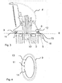
- Fig. 3 shows a longitudinal section through the axis of rotation of the embodiment according to Fig. 1
- the mirror 3 carries for the Abklapp- and rotational movement of the mirror head 2 a rivet or a folding motor.
- the axis of rotation protrudes into the mirror head and the carrier of the mirror head is rotatably connected to this axis.
- the lower edge of the housing cover 4,4 'of the mirror head moves during Fold over the plane E, which is shown in dashed lines.
- the mirror base cover 5 with the mirror base remains rigidly connected to the vehicle.
- the lighting adapter 6 is mounted on the lower edge of the housing cover 4,4 'and is in this example rigidly connected to the housing cover 4, 4'.
- the lighting adapter 6 has a low height and is therefore easy to integrate.
- the light window 9 can be seen, which closes the entire lower edge of the housing cover. Behind the light window 9, an LED 11 is arranged, which is mounted on a rear housing wall 13 with a printed circuit board 14.
- the lighting adapter 6 is mounted as a module from below on the housing covers 4, 4 '. All types of fastening are conceivable.
- a cover piece 4 "identical in construction to the outer dimensions is mounted, this cover piece 4" being of annular design.
- the lighting intermediate piece 6 is visible from all sides and has a closed, ellipsoidal outer contour.
- the lighting adapter comprises an inner cavity and is thus annular.
- the term ellipsoidal contour of the illumination intermediate piece is intended to include contours from the circle, via an ellipse, as well as pressed or compressed ellipses or rectangular structures with flattened corners and closed freeforms, which lead to annular spacers.
- the lighting adapter 6 is supplied with electrical voltage via a cable harness, which is guided by the hollow rivet in the interior of the mirror head.
- the contacting is achieved by means of a connector which is attached to the lighting adapter.
- the lower end edge 15 is formed so that it can easily move against the mirror base cover, but does not have too large a gap against the mirror base cover, to avoid problems with wind noise. It is also possible to provide the lower end edge 15 with a molded seal.
- the lighting adapter 6 is not with the components of the pivotable mirror head but with the Mirror foot cover 5 connected.
- the lighting adapter is then formed with an upper end edge 16 which is movable against the housing covers 4,4 '.
- the electrical supply in such an arrangement via branches of the wiring harness in the mirror or via an electrical connection from the mirror head. If no lighting is to be mounted in the mirror, the lighting adapter 6 is replaced by a foot cover 17, which consists only of a simple ring of the same material as the foot cover.
- the lighting adapter uses the same housing covers for illuminated or unlit exterior mirrors and only uses either the lighting adapter or cover with the same external dimensions.
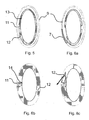
- FIG. 4 to FIG. 6 show various embodiments of the illumination intermediate piece 6 according to the invention in a plan view.
- the light window 9 and the housing rear wall 13 form a ring which encloses an inner cavity.
- three LEDs 11 are mounted, which are applied to the printed circuit board 14.
- the circuit board extends only in the area of the LEDs.
- the LEDs shine through the light window and preferably illuminate the front portion of the lighting fixture 6.
- the LEDs are distributed throughout the entire internal space of the lighting fixture. It makes sense to mount the LEDs on a flexible circuit board 14 and to attach them in the housing of the lighting adapter.
- Fig. 5 shows an embodiment of the illumination intermediate piece 6 with an integrated light guide 12.
- the light of the LED 11 is coupled into the light guide 12, which extends along the contour of the light window 9. If the LED is activated, the entire lighting adapter 6 is illuminated.
- the light window 9 is interrupted by covers 7, which shield the light from the driver or other road users.
- FIG. 6a is a two LEDs installed, which have a separate area of the lighting adapter illuminates. As a result, different lighting functions can be realized.
- the light window directly forms a light guide, into which the light of at least one LED is fed.
- the LEDs protrude into the light guide, or the light guide 9 is formed so that branching is formed, in which the light is coupled.
- a deflection element 18 is used, which is designed as a prism.
- the prismatic structure may have further surfaces than the image shown only schematically.
- the coupling does not necessarily have to be done on the front side, but can also be done from below or on top of the prism. With the deflection optics, it is possible to redirect light to direct it either towards the driver or away from the driver.
- FIG. 7 and FIG. 8 show an outside mirror as it is common for mounting on the mirror triangle of the vehicle.
- the lighting adapter 6 is also mounted in this embodiment between mirror and mirror head and can be both rigidly connected to the mirror base cover 5 or rigidly with the housing cover 4, 4 '. Depending on the version, the lighting adapter rotates with the mirror head or remains rigidly connected to the mirror base.
- a housing element is used, which corresponds to the outer dimension of the lighting intermediate piece.
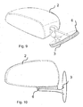
- Fig. 9 shows an embodiment that under the EP 10180683 is logged in. Between the mounting plane on the vehicle and the pivotable mirror head, the lighting adapter 6 is installed as an annular component.
- FIG. 10 shows an exterior mirror, which sits on a mirror base, which is designed as a rocker from the mirror triangle.
- the mirror connects the mirror head 2 hinged to the vehicle.
- the mirror base has a lighting
- the bulbs used are preferably LEDs, but the invention is not limited to the use of these bulbs.
- the use of incandescent lamps, EL films, OLEDs or further developments of lamps is also included.
Landscapes
- Engineering & Computer Science (AREA)
- Mechanical Engineering (AREA)
- Multimedia (AREA)
- Lighting Device Outwards From Vehicle And Optical Signal (AREA)
- Rear-View Mirror Devices That Are Mounted On The Exterior Of The Vehicle (AREA)
Claims (12)
- Ensemble formant rétroviseur extérieur comportant une embase de rétroviseur et une tête de rétroviseur montée de manière rotative, dans lequel la tête de rétroviseur (2) et l'embase de rétroviseur sont recouvertes par des recouvrements de boîtier (4, 4') et un recouvrement d'embase de rétroviseur (5), et l'ensemble formant rétroviseur extérieur (1) comporte au moins un élément lumineux, dans lequel l'élément lumineux est un élément intermédiaire d'éclairage (6) qui est disposé entre la tête de rétroviseur (2) et l'embase de rétroviseur (3), caractérisé en ce que l'élément intermédiaire d'éclairage présente un contour extérieur ellipsoïde fermé, avec au moins une fenêtre de lumière (9) suivant le contour extérieur de l'élément intermédiaire qui est visible de l'extérieur de tous les côtés.
- Ensemble formant rétroviseur extérieur selon la revendication 1, caractérisé en ce que l'élément intermédiaire d'éclairage (6) est relié de manière rigide au au moins un recouvrement de boîtier (4, 4) de la tête de rétroviseur.
- Ensemble formant rétroviseur extérieur selon la revendication 1, caractérisé en ce que l'élément intermédiaire d'éclairage (6) est relié de manière rigide au au moins un recouvrement d'embase de rétroviseur (5) de l'embase de rétroviseur.
- Ensemble formant rétroviseur extérieur selon la revendication 1, caractérisé en ce que l'élément intermédiaire d'éclairage (6) présente au moins une source d'éclairage (11) et/ou au moins un élément conducteur de lumière (12).
- Ensemble formant rétroviseur extérieur selon la revendication 1, caractérisé en ce que le au moins un élément conducteur de lumière (12) est disposé parallèlement à la fenêtre de lumière (9).
- Ensemble formant rétroviseur extérieur selon la revendication 4, caractérisé en ce que le au moins un élément conducteur de lumière (12) remplace la fenêtre de lumière (9).
- Ensemble formant rétroviseur extérieur selon la revendication 1, caractérisé en ce que l'élément intermédiaire d'éclairage comprend au moins une optique de déflexion.
- Ensemble formant rétroviseur extérieur selon la revendication 4, caractérisé en ce que la au moins une source d'éclairage (11) est montée sur une carte de circuits imprimés (14).
- Ensemble formant rétroviseur extérieur selon la revendication 8, caractérisé en ce que la carte de circuits imprimés (14) est une carte de circuits imprimés flexible.
- Ensemble formant rétroviseur extérieur selon la revendication 1, caractérisé en ce qu'un bord extérieur (15, 16) de l'élément intermédiaire d'éclairage (6) est formé de manière à ce qu'il soit mobile sur le recouvrement de boîtier.
- Ensemble formant rétroviseur extérieur selon la revendication 1, caractérisé en ce qu'un bord extérieur (15, 16) de l'élément intermédiaire d'éclairage (6) est formé d'un seul tenant avec un joint d'étanchéité moulé par injection.
- Ensemble formant rétroviseur extérieur selon la revendication 1, caractérisé en ce que au moins une fonction d'éclairage est réalisée, comme des clignotants, des voyants lumineux pour système d'assistance, des feux diurnes, des feux de position, des éclairages de sécurité, un gyrophare bleu.
Priority Applications (1)
| Application Number | Priority Date | Filing Date | Title |
|---|---|---|---|
| EP20100194468 EP2463156B1 (fr) | 2010-12-10 | 2010-12-10 | Elément intermédiaire d'éclairage |
Applications Claiming Priority (1)
| Application Number | Priority Date | Filing Date | Title |
|---|---|---|---|
| EP20100194468 EP2463156B1 (fr) | 2010-12-10 | 2010-12-10 | Elément intermédiaire d'éclairage |
Publications (2)
| Publication Number | Publication Date |
|---|---|
| EP2463156A1 EP2463156A1 (fr) | 2012-06-13 |
| EP2463156B1 true EP2463156B1 (fr) | 2014-04-16 |
Family
ID=43923781
Family Applications (1)
| Application Number | Title | Priority Date | Filing Date |
|---|---|---|---|
| EP20100194468 Not-in-force EP2463156B1 (fr) | 2010-12-10 | 2010-12-10 | Elément intermédiaire d'éclairage |
Country Status (1)
| Country | Link |
|---|---|
| EP (1) | EP2463156B1 (fr) |
Families Citing this family (1)
| Publication number | Priority date | Publication date | Assignee | Title |
|---|---|---|---|---|
| DE102020101252A1 (de) * | 2020-01-21 | 2021-07-22 | Bayerische Motoren Werke Aktiengesellschaft | Rückspiegel für ein einspuriges Kraftfahrzeug |
Family Cites Families (9)
| Publication number | Priority date | Publication date | Assignee | Title |
|---|---|---|---|---|
| DE29702746U1 (de) | 1997-02-18 | 1997-04-03 | Reitter & Schefenacker GmbH & Co. KG, 73730 Esslingen | Außenrückblickspiegel für Fahrzeuge, vorzugsweise für Kraftfahrzeuge |
| US6817742B2 (en) * | 2003-01-24 | 2004-11-16 | Rocky Lin | Vehicle rearview mirror assembly with color changing legs |
| WO2007005942A2 (fr) | 2005-07-06 | 2007-01-11 | Donnelly Corporation | Ensemble de retroviseur exterieur pour vehicule equipe d'un indicateur d'angle mort |
| DE202005014268U1 (de) | 2005-09-09 | 2005-12-15 | Fer Fahrzeugelektrik Gmbh | Fahrzeugleuchte mit einer einstückigen Lichtleiter-Blenden-Einheit |
| DE102006048323A1 (de) * | 2006-10-06 | 2008-04-10 | Schefenacker Patents S.à.r.l. | Außenrückblickspiegel für Fahrzeuge, vorzugsweise für Kraftfahrzeuge |
| JP4648889B2 (ja) * | 2006-11-16 | 2011-03-09 | 川崎重工業株式会社 | 車両用ミラー・方向指示器装置 |
| DE202006019027U1 (de) * | 2006-12-16 | 2007-02-15 | Bühler, Edmund | Außenspiegel für ein Kraftfahrzeug |
| US20080186723A1 (en) * | 2007-02-05 | 2008-08-07 | Chi-San Huang | Two-sided light-passing device for the additional warning light of an automobile rear-view mirror |
| JP5048433B2 (ja) * | 2007-09-19 | 2012-10-17 | 本田技研工業株式会社 | 鞍乗り型車両のウインカ一体型バックミラー |
-
2010
- 2010-12-10 EP EP20100194468 patent/EP2463156B1/fr not_active Not-in-force
Also Published As
| Publication number | Publication date |
|---|---|
| EP2463156A1 (fr) | 2012-06-13 |
Similar Documents
| Publication | Publication Date | Title |
|---|---|---|
| EP1914118B1 (fr) | Miroir extérieur avec moyen lumineux | |
| EP2762361B1 (fr) | Unité d'éclairage | |
| EP1598237B1 (fr) | Rétroviseur extérieur de véhicule | |
| DE19538770B4 (de) | Außenrückblickspiegel für Fahrzeuge, vorzugsweise für Kraftfahrzeuge | |
| EP1195296A2 (fr) | Feu latéral indicateur de direction | |
| EP0858932A2 (fr) | Rétroviseur extérieur de véhicules, en particulier à moteur | |
| WO2005018987A1 (fr) | Dispositif d'eclairage de vehicules | |
| EP1923266B1 (fr) | Rétroviseur extérieur pour véhicules | |
| DE102019210283A1 (de) | Außenrückspiegelanordnung mit integrierter Batterieladeanzeigefunktion | |
| WO2005100089A1 (fr) | Retroviseur exterieur pour vehicules, notamment pour vehicules a moteur | |
| DE10337615B3 (de) | Leuchtvorrichtung für Fahrzeuge | |
| DE3803510A1 (de) | Aussenrueckspiegel fuer kraftfahrzeuge | |
| DE29503774U1 (de) | Sicherheits- und Komfortleuchte für Kraftfahrzeuge | |
| WO2016096563A1 (fr) | Dispositif d'éclairage pour véhicule à moteur | |
| EP2463156B1 (fr) | Elément intermédiaire d'éclairage | |
| EP2243666B1 (fr) | Clignotant DEL minimal dans le rétroviseur extérieur | |
| DE102008055694A1 (de) | Stellrad | |
| EP3814172B1 (fr) | Procédé de fabrication d'un module de clignotant ainsi que module de clignotant, système de rétroviseur et véhicule automobile | |
| EP3443188B1 (fr) | Serrure de véhicule automobile | |
| DE102010034927A1 (de) | Vorrichtung zur Außenbeleuchtung eines Fahrzeugs und Verfahren zum Betreiben der Vorrichtung | |
| DE102018208804A1 (de) | Fahrzeug mit umgreifender Frontscheibe und elektrischer Komponente zwischen Vordersäule und Frontscheibe | |
| DE60311193T2 (de) | Signalleuchte und Anzeigevorrichtung die in einem teilweise aus der Kfz-Karosserie bestehendem Gehäuse angeordnet sind | |
| EP3132972B1 (fr) | Composant d'habillage pour véhicule | |
| DE20114989U1 (de) | Fahrzeugleuchte | |
| EP4321361B1 (fr) | Zone de toit d'un véhicule automobile |
Legal Events
| Date | Code | Title | Description |
|---|---|---|---|
| PUAI | Public reference made under article 153(3) epc to a published international application that has entered the european phase |
Free format text: ORIGINAL CODE: 0009012 |
|
| AK | Designated contracting states |
Kind code of ref document: A1 Designated state(s): AL AT BE BG CH CY CZ DE DK EE ES FI FR GB GR HR HU IE IS IT LI LT LU LV MC MK MT NL NO PL PT RO RS SE SI SK SM TR |
|
| AX | Request for extension of the european patent |
Extension state: BA ME |
|
| 17P | Request for examination filed |
Effective date: 20110802 |
|
| GRAP | Despatch of communication of intention to grant a patent |
Free format text: ORIGINAL CODE: EPIDOSNIGR1 |
|
| INTG | Intention to grant announced |
Effective date: 20131121 |
|
| GRAS | Grant fee paid |
Free format text: ORIGINAL CODE: EPIDOSNIGR3 |
|
| GRAA | (expected) grant |
Free format text: ORIGINAL CODE: 0009210 |
|
| AK | Designated contracting states |
Kind code of ref document: B1 Designated state(s): AL AT BE BG CH CY CZ DE DK EE ES FI FR GB GR HR HU IE IS IT LI LT LU LV MC MK MT NL NO PL PT RO RS SE SI SK SM TR |
|
| REG | Reference to a national code |
Ref country code: GB Ref legal event code: FG4D Free format text: NOT ENGLISH |
|
| REG | Reference to a national code |
Ref country code: CH Ref legal event code: EP |
|
| REG | Reference to a national code |
Ref country code: AT Ref legal event code: REF Ref document number: 662307 Country of ref document: AT Kind code of ref document: T Effective date: 20140515 |
|
| REG | Reference to a national code |
Ref country code: IE Ref legal event code: FG4D Free format text: LANGUAGE OF EP DOCUMENT: GERMAN |
|
| REG | Reference to a national code |
Ref country code: DE Ref legal event code: R096 Ref document number: 502010006659 Country of ref document: DE Effective date: 20140528 |
|
| REG | Reference to a national code |
Ref country code: NL Ref legal event code: VDEP Effective date: 20140416 |
|
| REG | Reference to a national code |
Ref country code: LT Ref legal event code: MG4D |
|
| PG25 | Lapsed in a contracting state [announced via postgrant information from national office to epo] |
Ref country code: GR Free format text: LAPSE BECAUSE OF FAILURE TO SUBMIT A TRANSLATION OF THE DESCRIPTION OR TO PAY THE FEE WITHIN THE PRESCRIBED TIME-LIMIT Effective date: 20140717 Ref country code: NL Free format text: LAPSE BECAUSE OF FAILURE TO SUBMIT A TRANSLATION OF THE DESCRIPTION OR TO PAY THE FEE WITHIN THE PRESCRIBED TIME-LIMIT Effective date: 20140416 Ref country code: IS Free format text: LAPSE BECAUSE OF FAILURE TO SUBMIT A TRANSLATION OF THE DESCRIPTION OR TO PAY THE FEE WITHIN THE PRESCRIBED TIME-LIMIT Effective date: 20140816 Ref country code: BG Free format text: LAPSE BECAUSE OF FAILURE TO SUBMIT A TRANSLATION OF THE DESCRIPTION OR TO PAY THE FEE WITHIN THE PRESCRIBED TIME-LIMIT Effective date: 20140716 Ref country code: LT Free format text: LAPSE BECAUSE OF FAILURE TO SUBMIT A TRANSLATION OF THE DESCRIPTION OR TO PAY THE FEE WITHIN THE PRESCRIBED TIME-LIMIT Effective date: 20140416 Ref country code: FI Free format text: LAPSE BECAUSE OF FAILURE TO SUBMIT A TRANSLATION OF THE DESCRIPTION OR TO PAY THE FEE WITHIN THE PRESCRIBED TIME-LIMIT Effective date: 20140416 Ref country code: NO Free format text: LAPSE BECAUSE OF FAILURE TO SUBMIT A TRANSLATION OF THE DESCRIPTION OR TO PAY THE FEE WITHIN THE PRESCRIBED TIME-LIMIT Effective date: 20140716 Ref country code: CY Free format text: LAPSE BECAUSE OF FAILURE TO SUBMIT A TRANSLATION OF THE DESCRIPTION OR TO PAY THE FEE WITHIN THE PRESCRIBED TIME-LIMIT Effective date: 20140416 |
|
| PG25 | Lapsed in a contracting state [announced via postgrant information from national office to epo] |
Ref country code: HR Free format text: LAPSE BECAUSE OF FAILURE TO SUBMIT A TRANSLATION OF THE DESCRIPTION OR TO PAY THE FEE WITHIN THE PRESCRIBED TIME-LIMIT Effective date: 20140416 Ref country code: SE Free format text: LAPSE BECAUSE OF FAILURE TO SUBMIT A TRANSLATION OF THE DESCRIPTION OR TO PAY THE FEE WITHIN THE PRESCRIBED TIME-LIMIT Effective date: 20140416 Ref country code: RS Free format text: LAPSE BECAUSE OF FAILURE TO SUBMIT A TRANSLATION OF THE DESCRIPTION OR TO PAY THE FEE WITHIN THE PRESCRIBED TIME-LIMIT Effective date: 20140416 Ref country code: LV Free format text: LAPSE BECAUSE OF FAILURE TO SUBMIT A TRANSLATION OF THE DESCRIPTION OR TO PAY THE FEE WITHIN THE PRESCRIBED TIME-LIMIT Effective date: 20140416 Ref country code: ES Free format text: LAPSE BECAUSE OF FAILURE TO SUBMIT A TRANSLATION OF THE DESCRIPTION OR TO PAY THE FEE WITHIN THE PRESCRIBED TIME-LIMIT Effective date: 20140416 Ref country code: PL Free format text: LAPSE BECAUSE OF FAILURE TO SUBMIT A TRANSLATION OF THE DESCRIPTION OR TO PAY THE FEE WITHIN THE PRESCRIBED TIME-LIMIT Effective date: 20140416 |
|
| PG25 | Lapsed in a contracting state [announced via postgrant information from national office to epo] |
Ref country code: PT Free format text: LAPSE BECAUSE OF FAILURE TO SUBMIT A TRANSLATION OF THE DESCRIPTION OR TO PAY THE FEE WITHIN THE PRESCRIBED TIME-LIMIT Effective date: 20140818 |
|
| REG | Reference to a national code |
Ref country code: DE Ref legal event code: R097 Ref document number: 502010006659 Country of ref document: DE |
|
| PG25 | Lapsed in a contracting state [announced via postgrant information from national office to epo] |
Ref country code: SK Free format text: LAPSE BECAUSE OF FAILURE TO SUBMIT A TRANSLATION OF THE DESCRIPTION OR TO PAY THE FEE WITHIN THE PRESCRIBED TIME-LIMIT Effective date: 20140416 Ref country code: RO Free format text: LAPSE BECAUSE OF FAILURE TO SUBMIT A TRANSLATION OF THE DESCRIPTION OR TO PAY THE FEE WITHIN THE PRESCRIBED TIME-LIMIT Effective date: 20140416 Ref country code: EE Free format text: LAPSE BECAUSE OF FAILURE TO SUBMIT A TRANSLATION OF THE DESCRIPTION OR TO PAY THE FEE WITHIN THE PRESCRIBED TIME-LIMIT Effective date: 20140416 Ref country code: DK Free format text: LAPSE BECAUSE OF FAILURE TO SUBMIT A TRANSLATION OF THE DESCRIPTION OR TO PAY THE FEE WITHIN THE PRESCRIBED TIME-LIMIT Effective date: 20140416 Ref country code: CZ Free format text: LAPSE BECAUSE OF FAILURE TO SUBMIT A TRANSLATION OF THE DESCRIPTION OR TO PAY THE FEE WITHIN THE PRESCRIBED TIME-LIMIT Effective date: 20140416 |
|
| PLBE | No opposition filed within time limit |
Free format text: ORIGINAL CODE: 0009261 |
|
| STAA | Information on the status of an ep patent application or granted ep patent |
Free format text: STATUS: NO OPPOSITION FILED WITHIN TIME LIMIT |
|
| 26N | No opposition filed |
Effective date: 20150119 |
|
| PG25 | Lapsed in a contracting state [announced via postgrant information from national office to epo] |
Ref country code: IT Free format text: LAPSE BECAUSE OF FAILURE TO SUBMIT A TRANSLATION OF THE DESCRIPTION OR TO PAY THE FEE WITHIN THE PRESCRIBED TIME-LIMIT Effective date: 20140416 |
|
| REG | Reference to a national code |
Ref country code: DE Ref legal event code: R097 Ref document number: 502010006659 Country of ref document: DE Effective date: 20150119 |
|
| PG25 | Lapsed in a contracting state [announced via postgrant information from national office to epo] |
Ref country code: BE Free format text: LAPSE BECAUSE OF NON-PAYMENT OF DUE FEES Effective date: 20141231 |
|
| PG25 | Lapsed in a contracting state [announced via postgrant information from national office to epo] |
Ref country code: LU Free format text: LAPSE BECAUSE OF FAILURE TO SUBMIT A TRANSLATION OF THE DESCRIPTION OR TO PAY THE FEE WITHIN THE PRESCRIBED TIME-LIMIT Effective date: 20141210 Ref country code: SI Free format text: LAPSE BECAUSE OF FAILURE TO SUBMIT A TRANSLATION OF THE DESCRIPTION OR TO PAY THE FEE WITHIN THE PRESCRIBED TIME-LIMIT Effective date: 20140416 |
|
| REG | Reference to a national code |
Ref country code: CH Ref legal event code: PL |
|
| REG | Reference to a national code |
Ref country code: IE Ref legal event code: MM4A |
|
| PG25 | Lapsed in a contracting state [announced via postgrant information from national office to epo] |
Ref country code: LI Free format text: LAPSE BECAUSE OF NON-PAYMENT OF DUE FEES Effective date: 20141231 Ref country code: CH Free format text: LAPSE BECAUSE OF NON-PAYMENT OF DUE FEES Effective date: 20141231 Ref country code: IE Free format text: LAPSE BECAUSE OF NON-PAYMENT OF DUE FEES Effective date: 20141210 |
|
| REG | Reference to a national code |
Ref country code: FR Ref legal event code: PLFP Year of fee payment: 6 |
|
| PG25 | Lapsed in a contracting state [announced via postgrant information from national office to epo] |
Ref country code: SM Free format text: LAPSE BECAUSE OF FAILURE TO SUBMIT A TRANSLATION OF THE DESCRIPTION OR TO PAY THE FEE WITHIN THE PRESCRIBED TIME-LIMIT Effective date: 20140416 |
|
| PG25 | Lapsed in a contracting state [announced via postgrant information from national office to epo] |
Ref country code: MC Free format text: LAPSE BECAUSE OF FAILURE TO SUBMIT A TRANSLATION OF THE DESCRIPTION OR TO PAY THE FEE WITHIN THE PRESCRIBED TIME-LIMIT Effective date: 20140416 |
|
| PG25 | Lapsed in a contracting state [announced via postgrant information from national office to epo] |
Ref country code: MT Free format text: LAPSE BECAUSE OF FAILURE TO SUBMIT A TRANSLATION OF THE DESCRIPTION OR TO PAY THE FEE WITHIN THE PRESCRIBED TIME-LIMIT Effective date: 20140416 Ref country code: TR Free format text: LAPSE BECAUSE OF FAILURE TO SUBMIT A TRANSLATION OF THE DESCRIPTION OR TO PAY THE FEE WITHIN THE PRESCRIBED TIME-LIMIT Effective date: 20140416 Ref country code: HU Free format text: LAPSE BECAUSE OF FAILURE TO SUBMIT A TRANSLATION OF THE DESCRIPTION OR TO PAY THE FEE WITHIN THE PRESCRIBED TIME-LIMIT; INVALID AB INITIO Effective date: 20101210 |
|
| REG | Reference to a national code |
Ref country code: FR Ref legal event code: PLFP Year of fee payment: 7 |
|
| REG | Reference to a national code |
Ref country code: AT Ref legal event code: MM01 Ref document number: 662307 Country of ref document: AT Kind code of ref document: T Effective date: 20151210 |
|
| PG25 | Lapsed in a contracting state [announced via postgrant information from national office to epo] |
Ref country code: AT Free format text: LAPSE BECAUSE OF NON-PAYMENT OF DUE FEES Effective date: 20151210 |
|
| REG | Reference to a national code |
Ref country code: FR Ref legal event code: PLFP Year of fee payment: 8 |
|
| PG25 | Lapsed in a contracting state [announced via postgrant information from national office to epo] |
Ref country code: MK Free format text: LAPSE BECAUSE OF FAILURE TO SUBMIT A TRANSLATION OF THE DESCRIPTION OR TO PAY THE FEE WITHIN THE PRESCRIBED TIME-LIMIT Effective date: 20140416 |
|
| PG25 | Lapsed in a contracting state [announced via postgrant information from national office to epo] |
Ref country code: AL Free format text: LAPSE BECAUSE OF FAILURE TO SUBMIT A TRANSLATION OF THE DESCRIPTION OR TO PAY THE FEE WITHIN THE PRESCRIBED TIME-LIMIT Effective date: 20140416 |
|
| REG | Reference to a national code |
Ref country code: DE Ref legal event code: R084 Ref document number: 502010006659 Country of ref document: DE |
|
| PGFP | Annual fee paid to national office [announced via postgrant information from national office to epo] |
Ref country code: GB Payment date: 20221223 Year of fee payment: 13 Ref country code: FR Payment date: 20221222 Year of fee payment: 13 |
|
| P01 | Opt-out of the competence of the unified patent court (upc) registered |
Effective date: 20230616 |
|
| PGFP | Annual fee paid to national office [announced via postgrant information from national office to epo] |
Ref country code: DE Payment date: 20231214 Year of fee payment: 14 |
|
| GBPC | Gb: european patent ceased through non-payment of renewal fee |
Effective date: 20231210 |
|
| PG25 | Lapsed in a contracting state [announced via postgrant information from national office to epo] |
Ref country code: GB Free format text: LAPSE BECAUSE OF NON-PAYMENT OF DUE FEES Effective date: 20231210 |
|
| PG25 | Lapsed in a contracting state [announced via postgrant information from national office to epo] |
Ref country code: FR Free format text: LAPSE BECAUSE OF NON-PAYMENT OF DUE FEES Effective date: 20231231 |
|
| PG25 | Lapsed in a contracting state [announced via postgrant information from national office to epo] |
Ref country code: GB Free format text: LAPSE BECAUSE OF NON-PAYMENT OF DUE FEES Effective date: 20231210 Ref country code: FR Free format text: LAPSE BECAUSE OF NON-PAYMENT OF DUE FEES Effective date: 20231231 |
|
| REG | Reference to a national code |
Ref country code: DE Ref legal event code: R119 Ref document number: 502010006659 Country of ref document: DE |
|
| PG25 | Lapsed in a contracting state [announced via postgrant information from national office to epo] |
Ref country code: DE Free format text: LAPSE BECAUSE OF NON-PAYMENT OF DUE FEES Effective date: 20250701 |