EP2463175A2 - Procédé de détection de défauts de surface - Google Patents
Procédé de détection de défauts de surface Download PDFInfo
- Publication number
- EP2463175A2 EP2463175A2 EP11450150A EP11450150A EP2463175A2 EP 2463175 A2 EP2463175 A2 EP 2463175A2 EP 11450150 A EP11450150 A EP 11450150A EP 11450150 A EP11450150 A EP 11450150A EP 2463175 A2 EP2463175 A2 EP 2463175A2
- Authority
- EP
- European Patent Office
- Prior art keywords
- light
- line sensor
- pixel
- sensor
- light sources
- Prior art date
- Legal status (The legal status is an assumption and is not a legal conclusion. Google has not performed a legal analysis and makes no representation as to the accuracy of the status listed.)
- Granted
Links
- 238000000034 method Methods 0.000 title claims abstract description 56
- 230000007547 defect Effects 0.000 title claims description 16
- 238000001514 detection method Methods 0.000 claims description 20
- 230000033001 locomotion Effects 0.000 claims description 15
- 238000012935 Averaging Methods 0.000 claims description 10
- 206010037844 rash Diseases 0.000 claims description 7
- 230000006978 adaptation Effects 0.000 claims description 5
- 238000003708 edge detection Methods 0.000 claims description 4
- 230000002950 deficient Effects 0.000 claims description 3
- 238000005457 optimization Methods 0.000 claims description 3
- 238000001454 recorded image Methods 0.000 claims description 3
- 239000002184 metal Substances 0.000 claims description 2
- 238000007689 inspection Methods 0.000 description 6
- 238000012360 testing method Methods 0.000 description 5
- 230000004907 flux Effects 0.000 description 4
- 230000006870 function Effects 0.000 description 4
- 230000000007 visual effect Effects 0.000 description 4
- 102100028043 Fibroblast growth factor 3 Human genes 0.000 description 3
- 102100024061 Integrator complex subunit 1 Human genes 0.000 description 3
- 101710092857 Integrator complex subunit 1 Proteins 0.000 description 3
- 108050002021 Integrator complex subunit 2 Proteins 0.000 description 3
- 238000004422 calculation algorithm Methods 0.000 description 3
- 239000000463 material Substances 0.000 description 3
- 230000003287 optical effect Effects 0.000 description 3
- 230000008569 process Effects 0.000 description 3
- 230000035945 sensitivity Effects 0.000 description 3
- 230000003595 spectral effect Effects 0.000 description 3
- 238000004458 analytical method Methods 0.000 description 2
- 230000002238 attenuated effect Effects 0.000 description 2
- 230000006399 behavior Effects 0.000 description 2
- 238000007635 classification algorithm Methods 0.000 description 2
- 230000006735 deficit Effects 0.000 description 2
- 230000004069 differentiation Effects 0.000 description 2
- 238000005315 distribution function Methods 0.000 description 2
- 238000005259 measurement Methods 0.000 description 2
- 238000003909 pattern recognition Methods 0.000 description 2
- 239000002243 precursor Substances 0.000 description 2
- 238000012545 processing Methods 0.000 description 2
- 238000005096 rolling process Methods 0.000 description 2
- 238000007476 Maximum Likelihood Methods 0.000 description 1
- 238000005299 abrasion Methods 0.000 description 1
- 238000013459 approach Methods 0.000 description 1
- 238000013528 artificial neural network Methods 0.000 description 1
- 230000008901 benefit Effects 0.000 description 1
- 230000015572 biosynthetic process Effects 0.000 description 1
- 238000004364 calculation method Methods 0.000 description 1
- 230000006835 compression Effects 0.000 description 1
- 238000007906 compression Methods 0.000 description 1
- 230000001054 cortical effect Effects 0.000 description 1
- 238000011161 development Methods 0.000 description 1
- 230000018109 developmental process Effects 0.000 description 1
- 230000000694 effects Effects 0.000 description 1
- 238000005286 illumination Methods 0.000 description 1
- 238000010191 image analysis Methods 0.000 description 1
- 230000001771 impaired effect Effects 0.000 description 1
- 238000011835 investigation Methods 0.000 description 1
- 238000010801 machine learning Methods 0.000 description 1
- 238000004519 manufacturing process Methods 0.000 description 1
- 239000000203 mixture Substances 0.000 description 1
- 230000009467 reduction Effects 0.000 description 1
- 238000002310 reflectometry Methods 0.000 description 1
- 230000004044 response Effects 0.000 description 1
- 238000003860 storage Methods 0.000 description 1
- 230000001502 supplementing effect Effects 0.000 description 1
- 238000012876 topography Methods 0.000 description 1
- 238000011179 visual inspection Methods 0.000 description 1
Images


Classifications
-
- G—PHYSICS
- G01—MEASURING; TESTING
- G01B—MEASURING LENGTH, THICKNESS OR SIMILAR LINEAR DIMENSIONS; MEASURING ANGLES; MEASURING AREAS; MEASURING IRREGULARITIES OF SURFACES OR CONTOURS
- G01B11/00—Measuring arrangements characterised by the use of optical techniques
- G01B11/24—Measuring arrangements characterised by the use of optical techniques for measuring contours or curvatures
-
- B—PERFORMING OPERATIONS; TRANSPORTING
- B61—RAILWAYS
- B61L—GUIDING RAILWAY TRAFFIC; ENSURING THE SAFETY OF RAILWAY TRAFFIC
- B61L23/00—Control, warning or like safety means along the route or between vehicles or trains
- B61L23/04—Control, warning or like safety means along the route or between vehicles or trains for monitoring the mechanical state of the route
- B61L23/042—Track changes detection
- B61L23/045—Rail wear
-
- G—PHYSICS
- G01—MEASURING; TESTING
- G01N—INVESTIGATING OR ANALYSING MATERIALS BY DETERMINING THEIR CHEMICAL OR PHYSICAL PROPERTIES
- G01N21/00—Investigating or analysing materials by the use of optical means, i.e. using sub-millimetre waves, infrared, visible or ultraviolet light
- G01N21/84—Systems specially adapted for particular applications
- G01N21/88—Investigating the presence of flaws or contamination
- G01N21/95—Investigating the presence of flaws or contamination characterised by the material or shape of the object to be examined
- G01N21/9515—Objects of complex shape, e.g. examined with use of a surface follower device
-
- G—PHYSICS
- G01—MEASURING; TESTING
- G01N—INVESTIGATING OR ANALYSING MATERIALS BY DETERMINING THEIR CHEMICAL OR PHYSICAL PROPERTIES
- G01N21/00—Investigating or analysing materials by the use of optical means, i.e. using sub-millimetre waves, infrared, visible or ultraviolet light
- G01N21/84—Systems specially adapted for particular applications
- G01N21/88—Investigating the presence of flaws or contamination
- G01N21/89—Investigating the presence of flaws or contamination in moving material, e.g. running paper or textiles
- G01N21/8914—Investigating the presence of flaws or contamination in moving material, e.g. running paper or textiles characterised by the material examined
- G01N2021/8918—Metal
Definitions
- the invention relates to a method for inspecting the surface of elongate objects having a substantially constant cross section and smooth surface according to the preamble of patent claim 1 and a device according to the preamble of claim 12. Furthermore, the invention relates to a method according to claim 24 and a data carrier according to claim 28th
- the invention is used in particular in the field of automated testing of rails.
- a time or a point in time is to be understood in each case as meaning a particular recording time which is indicated by an integer.
- the respective integer indicates a number of reference intervals which have elapsed since a reference time.
- the reference time interval corresponds to a period of time between two recording times.
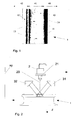
- Fig. 1 shows the image of a faulty rail with a number of different errors in plan view.
- Material defects such as outbreaks 11 or so-called head checks 14 are the result of small material outbreaks 11 in the rail 1. These material defects can occur at different areas of the rail 1, so breakouts 11 typically occur in the central region or driving mirror 41 of the rail, while head checks 14 typically the running edge 40 occur.
- Outbreaks 11 and head checks 14 are typical signs of defects in the rail 1 and are indicators of rail breakage.
- Precursors to outbreaks 11 or head checks 14 are microcracks 13 which are caused by plastic flow and abrasion, a consequence of the so-called rolling contact fatigue (FIG.
- the invention is illustrated by the detection of defects on the surface of rails, but is not limited to rails, but can be used quite generally for defect detection on the surface of any reflective surface object.
- the invention solves this problem in a method according to the preamble of claim 1 with the features of the characterizing part of claim 1.
- the invention solves this problem in a device according to the preamble of claim 12 with the features of the characterizing part of claim 12.
- the invention solves these Task in a method according to the preamble of claim 24 having the features of the characterizing part of claim 24.
- the two light sources emit light of different wavelengths and each of the pixel sensors separately determines the light intensity at each of the two wavelengths.
- the light from the first light source can be efficiently discriminated from the light of the second light source, and an easy detection of edges can be achieved.
- one of the two wavelengths of light in the range of the red light and the respective other wavelength of light in the range of the blue light is selected. This allows a good visual differentiation of the two light sources as well as a simple optical control of the method.
- each of the pixel sensors each comprise a first and a second sub-sensor, wherein the first sub-sensor measures light of the first wavelength and the second sub-sensor measures light of the second wavelength. This allows a particularly simple determination of the individual light intensity values.
- the two light sources emit light at different, separate, recurring time intervals, the first light source being activated during the first time interval and the first light intensity being equated to the intensity value detected by the respective pixel sensor and the second light intensity during the second time interval equated to the intensity value detected by the respective pixel sensor. This allows the implementation of the method with the same trained light sources.
- a further preferred aspect of the invention provides that the relative position and the relative orientation of the line sensor and the light sources are aligned on the basis of a reference object detected as faultless such that the image recorded with the line sensor is free of direct reflections of the light emitted by the light sources. This allows a trouble-free recording and improved edge detection.
- an edge or an error of the surface is detected as present if all four criteria are met. This enables a particularly reliable detection of surface defects.
- the first mean value and / or the second mean value is determined by forming a moving average, in particular by means of a Gaussian filter, which preferably sums a number of preceding and succeeding intensity values in a weighted manner.
- the predetermined value d is determined by the number by adaptation to the typically occurring crack width, whereby larger crack widths lead to an increase of the predetermined value, wherein the predetermined value d is set to 1 or 2 in particular.
- the two threshold values are determined by calibration or optimization, where appropriate in a calibration step a number of line images with known Errors are minimized and the number of undamaged points designated as defective, as well as the number of undetected errors, is minimized, and in particular the threshold values are each set to a value between 1.1 and 1.3.
- a break is considered to be detected if at least one edge has been detected within at least 60%, in particular at least 80% of the pixel sensors within a predetermined acquisition period, preferably between 10 and 50 line images ,
- the two light sources emit light of different wavelengths
- each of the pixel sensors separately determines the light intensity at each of the two wavelengths.
- one of the two wavelengths of light in the range of the red light and the respective other wavelength of light in the range of the blue light is selected. This allows a good visual differentiation of the two light sources as well as a simple optical control of the method.
- each of the pixel sensors each comprise a first and a second sub-sensor, wherein the first sub-sensor measures light of the first wavelength and the second sub-sensor measures light of the second wavelength. This allows a particularly simple determination of the individual light intensity values.
- a switching unit which controls the two light sources, so that the two light sources emit light at different, separate, recurring time intervals, wherein the switching unit activates the first light source during the first time interval, wherein the second light source is deactivated and the first light intensity is set equal to the intensity value detected by the respective pixel sensor, and wherein the switching unit activates the second light source during the second time interval, wherein the first light source is deactivated and the second light intensity is set equal to the intensity value detected by the respective pixel sensor.
- a further preferred aspect of the invention provides that the relative position and the relative orientation of the line sensor and the light sources are aligned on the basis of a reference object detected as faultless such that the image recorded by the line sensor is free from direct reflections of the light emitted by the light source. This allows a trouble-free recording and improved edge detection.
- the detector unit detects an edge as present if all four criteria are met. This enables a particularly reliable detection of surface defects.
- the averaging unit determines the first mean value and / or the second mean value by forming a moving average from the respective light intensity values, in particular by means of a Gaussian filter, which preferably sums a number of preceding and succeeding light intensity values ,
- the predetermined value d is determined by adaptation to the typically occurring crack width, whereby larger crack widths lead to an increase of the predetermined value, and wherein predetermined value is set in particular to 1 or 2.
- the two threshold values are respectively set to a value between 1.1 and 1.3.
- a fracture detection unit may be provided downstream of the individual detector units and detects a fracture if, within a predetermined acquisition period, preferably between 10 and 50 line images, in at least 60%, in particular at least 80%, of the pixel sensors each detect at least one edge.
- the movement unit is formed by a rail vehicle, which carries the line sensor and the two light sources and optionally on the object, in particular the rail is relatively movable or movable, and / or in that the line sensor and the two light sources are arranged so as to be stationary, the movement unit is designed to move the object relative to the line sensor and the two light sources.
- the a priori probability is determined as the probability of the occurrence of errors in a number of previously recorded digital images, the a priori probability being calculated by averaging the probability values arising from the classification method. This allows a particularly advantageous calibration and improves the recognition accuracy.
- the track body to be inspected consists of two rails 1, in the rail vehicle used two identical devices according to the invention are used, which are each arranged above one of the two rails 1. With both devices according to the invention, the process according to the invention, as shown below, is carried out in each case in parallel.
- the method can also be used in the testing of rails 1 in the course of production, wherein in this concrete alternative embodiment, the rail 1 is moved past the line sensor 2, while the line sensor 2 is fixed.
- the device according to the invention comprises two light sources, namely a first light source 31 and a second light source 32, which illuminate the object section of the rail 1 detected by the line sensor 2 with light of different spectral characteristics with different wavelengths I1, I2.
- the light sources 31, 32 are further mounted so that in the case of an undisturbed surface, ie in a new or undamaged rail 1, the specularly reflected light does not impinge on the line sensor 2. Only a portion of diffusely reflected light impinges directly on the individual sensor pixels 21 of the line sensor 2. Investigations on reflection behavior make such an arrangement advantageous ( Hoßfeld, M., Chu, W., Adameck, M., Eich, M .: Almost 3D vision system to classify metallic coins by their embossed topography. Electronic Letters on Computer Vision and Image Analysis 5 (4), 47-63 (2006 ))
- the first light source 31 is seen in the direction of travel or in the expansion direction z of the rail 1 is mounted in front of the line sensor 2 and the second light source 32 seen in the direction of travel mounted behind the line sensor 2.
- the first light source 31 emits light in the red spectral range in this particular embodiment of the invention
- the second light source 32 emits light in the blue spectral range.
- the line sensor 2 comprises sensor pixels 21 for receiving light with different wavelengths I1, I2.
- Each pixel sensor 21 has in each case a first output for the light intensity of light having the first wavelength I1 irradiated onto the pixel sensor 21 and a second output for the light intensity of light having the second wavelength I2 irradiated onto the pixel sensor 21.
- the individual values output by the individual outputs of the pixel sensors 21 are fed to a first channel, referred to as red channel 9 in connection with the use of red and blue light, and a second channel, hereinafter referred to as blue channel 10 ,
- wavelengths I1, I2 or light frequencies are used, which are in the range of ultraviolet light and / or infrared light.
- the red channel 9 is thus supplied with the intensity values of the pixel sensor 21 which are recorded at time intervals and which originate from reflections of the light emitted by the first (red) light source 31. Accordingly, the blue channel 10 is supplied with the temporally spaced intensity values of the pixel sensor 21 resulting from reflections of the light emitted from the second (blue) light source 31.
- the respective intensity values of the red channel 9 at a given time t are denoted by r t .
- the respective intensity values of the red channel 9 at the time 1 are denoted by r 1
- two intensity values r t and instead of a single pixel sensor 21 which at any time t b t at two wavelengths of light I1, determined I2, two separate sub-pixel sensors are used, one each of which the intensity at one of the two wavelengths of light I1 , I2, where the two sub-pixel sensors each have the same pick-up area.
- first light source 31 or the second light source 32 is arranged in the direction of travel or in the expansion direction z of the rail 1 in front of or behind the line sensor 2 or which of the two light sources emits red or blue light.
- the light irradiated from different directions can also be emitted with the same wavelength, in this case, the two wavelengths I1, I2 are the same.
- the two light sources are switched active at different time intervals (INT1, INT2), so that in the course of the processing of the intensity values recorded by the sensors, it is clarified whether a reflection image of light emitted by the first light source 31 or a reflection image of light emitted by the second light source 32 is present.
- the two light sources 31, 32 are controlled by means of a switching unit, which drives the two light sources 31, 32 to the different, mutually separated, recurring time intervals INT1, INT2.
- a switching unit which drives the two light sources 31, 32 to the different, mutually separated, recurring time intervals INT1, INT2.
- the first light source 31 is activated and the second light source 32 is deactivated.
- a first light intensity r t is detected, which is set equal to the intensity value detected by the respective pixel sensor 21.
- the switching unit activates the second light source 32 and deactivates the first light source 31.
- a second light intensity b t is detected, which is set equal to the intensity value detected by the respective pixel sensor 21.
- the reflection behavior of the surface of the rail 1 changes depending on which direction the light radiates onto the surface of the rail 1.
- Typical impairments of the rail surface are breakouts 11 and fractures 12. These impairments can be detected by analyzing the reflections of the light emitted by the light sources 31, 32, depending on position and color.
- burst detection calculations 11 are performed separately for each individual pixel sensor 21, the respective pixel sensor 21 determining both a blue light intensity value b t and a red light intensity value r t .
- Fig. 3 shows a profile section in the expansion direction z of the rail 1 with an outbreak 11. Furthermore, the output by means of the light sources 31, 32 light beams 33 and 34 are shown. In the presentation of the Fig. 3 the red light emitted from the first light source 31 hits the eruption 11 from the top right, while blue light emitted from the second light source 32 hits the eruption 11 from the top left.
- the intensity values recorded by one of the pixel sensors 21 of the line sensor 2 during the inspection travel are in Fig. 4 shown.
- a first channel 9 for the red color components and a second channel 10 for the blue color components are shown.
- the channels 9, 10 each comprise the intensity values for red and blue light recorded in the course of the inspection journey.
- intensity values r t , b t are plotted on the abscissa, the recording time t - or, thus, correlating - the respective measuring position.
- the left edge 16 of the breakout 11 reaches the receiving area of the line sensor 2, red light strikes from the top right, on the left edge 16 of the breakout 11, resulting in a specular reflection in the direction of the line sensor 2 at the left edge 16 of the breakout 11 , This results, as in Fig. 4
- the blue light of the second light source 32 coming from the left is attenuated by the specific shape of the outbreak 11, so that not even diffusely reflected light or a smaller part of the diffuse light is reflected reflected light hits the respective pixel sensor 21 of the line sensor 2.
- the blue channel 10 thus results in partial or complete shadowing, which results in a reduced or relatively smaller luminous flux in the direction of the line sensor 2 or of the respective pixel sensor 21.
- the red light coming from the first light source 31 is attenuated by the specific shape of the eruption 11, so that not even diffusely reflected light or a reduced proportion of the diffusely reflected light impinges on the respective pixel sensor 21 of the line sensor 2.
- the red channel 9 thus results in complete or partial shading, which results in a relatively smaller or reduced luminous flux in the direction of the line sensor 2.
- the determination of the relative intensity fluctuation caused by the reflection at an edge 16, 18 takes place by comparison of the local background reflection, which is determined by a sensor pixel and an average value r t, M b t, M.
- this mean value is determined by a sliding mean value formation and is determined separately for each pixel sensor 21 of the line sensor 2 at each time point.
- a mean value for the red channel 9 and the blue channel 10 is generally determined in each case, which is referred to below as r t, M or b t, M respectively.
- the result of the mean value filter can be carried out efficiently in a known manner either in the spatial domain as a sliding filter or in the frequency domain by means of the fast Fourier transform (FFT).
- FFT fast Fourier transform
- T 11 r t + 1 / r t . M ⁇ 1 / t r T 21 : r t - 1 / r t . M > t r T 31 : b t - 1 / b t . M ⁇ 1 / t b T 41 : b t + 1 / b t . M > t b
- T 31 can be used, wherein the ratio between the instantaneous intensity value and the mean value is compared with a threshold value 1 / t b . Accordingly, the determined intensity value of the red light increases with respect to the mean value of the red light, so that the criterion T 21 is satisfied.
- the threshold value can be adapted to the respective measurements and in the present exemplary embodiment lies in the range between 1.1 and 1.2.
- the threshold value is typically determined in the course of an optimization procedure in which, based on a number of known errors, a threshold parameter t b is searched for, with as many errors as possible being sought be detected but as few flawless surface areas are detected as defective.
- the recording intervals are selected to be shorter or the rail vehicle travels more slowly over the rails, then there are more than two recording intervals between the two edges 16, 18.
- provision can be made in an alternative embodiment will wait for several shots. Accordingly, for determining the criteria T, it is also possible to use times t + d, td, which have a greater distance from the respective pick-up point: T 1 ⁇ d : r t + d / r t . M ⁇ 1 / t r T 2 ⁇ d : r t - d / r t .
- the predetermined value d corresponds to a time offset.
- the predetermined value d is determined by the number by adaptation to the typical crack width. Larger crack widths lead to an increase of the predetermined value d, wherein the predetermined value (d) is set in particular to 1 or 2.
- the inventive method is in addition to the detection of edges 16, 18 of outbreaks also for detecting corresponding edges 16, 18 of head checks 14th and microcracks 13.
- the device according to the invention is advantageously used.
- a preferred embodiment of this device will be described below.
- the device comprises, as already described, a travel unit in the form of a rail vehicle, not shown.
- the device according to the invention can be mounted on a rail vehicle or a trailer or wagon.
- the two light sources 31, 32 and the line sensor 2 are arranged stationary relative to one another on the movement unit, there is no relative movement or relative pivoting between the two light sources 31, 32 and the line sensor 2.
- the line sensor 2 and the two light sources 31, 32 are arranged fixed and the rail 1 or the object 1 relative to the line sensor 2 and the two light sources 31, 32 are moved. There are no differences for the further determination of superficial errors.
- the device according to the invention comprises a receiving unit, which is connected to the line sensor 2 and stores the images taken by the line sensor according to their recording order.
- each of the incoming images is allocated a memory space in each case, wherein successively incoming images are each assigned an incrementally increased memory address. If necessary, compression methods for reducing the storage space can also be used.
- the intensity values of the individual line images can be accessed randomly. Furthermore, the different intensity values for the two wavelengths can also be accessed randomly.
- the recording unit is followed by an averaging unit which, for all of the pixel sensors 21 and for all times t, respectively has a moving average r t, M , b t, M for the light intensity values r t , b t recorded for the pixel sensor 21 for both light wavelengths I1, I2 determined.
- the averaging unit is followed by a detector unit which checks the following criteria T 11 , T 21 , T 31 , T 41 for all pixel sensors 21 and recording times t: T 11 : r t + 1 / r t . M ⁇ 1 / t r T 21 : r t - 1 / r t . M > t r T 31 : b t - 1 / b t . M ⁇ 1 / t b T 41 : b t + 1 / b t . M > t b .
- the detector unit is followed by an outbreak detection unit, which then detects an edge 16, 18 of an outbreak 11 as present if at least a certain number R of the criteria T 1d , T 2d , T 3d , T 4d is met.
- Fractions typically run largely normal to the longitudinal direction z of the rail 1 and have a very small extent in the longitudinal direction z of the rail 1.
- a number D of recordings is taken, which are recorded within a travel path which corresponds to the maximum extent of a break 12 in the longitudinal direction z of the rail 1.
- the number of those pixel sensors 21, of which an outbreak 11 has been detected is counted in each case via this number D of recordings within a recording interval [t, t + D] beginning at a time t.
- all the pixel sensors 21 of the line sensor 2 are connected to a breakage detection unit.
- a threshold value of 80% of the pixel sensors 21 of the line sensor 2, in whose receiving region the rail 1 is located indicates an outbreak 11, it can be assumed that in that a break 12 runs through the surface area recorded within the recording interval [t, t + D].
- the break detection unit outputs a signal in this regard.
- Fig. 1 shows a digital image 100 and the application of this method according to the invention for determining the error probability.
- Fig. 5 shows a digital image 100 and the application of this method according to the invention for determining the error probability.
- a digital image 100 of item 1 is created.
- the digital image 100 can be created by means of any image-forming method, for example also the recording method already described by means of the line sensor 2, but also by means of a digital area sensor.
- the digital image 100 is subsequently used to detect, locate and classify errors in the recorded image Item 1 used. Different error types C or error classes can occur here.
- Microcracking regions 13 are potential precursors to breakouts and rail breakages and are characterized by a characteristic texture.
- Abrasive zones 11 ' are formed when grinding rails, a measure to prevent rail damage.
- Abrasive zones 11 ' are likewise distinguished by a characteristic texture, which, however, differs from that of microcracks 13.
- Pixel 101 characterized by these surface textures are identified by texture analysis and classification:
- a Gabor filter bank Field, DJ: Relations between the natural images and the response properties of cortical cells. J. Optical Soc. At the. A 12, 2379-2394 (1987 ) respectively. Jähne, B .: Digital image processing, chap. 13.4.5: Quadrature filter, pp. 383-384. Springer, 5th Edn. (2002 )) with 3 scales and 6 orientations is applied to each color channel of the digital image.
- Each surface class is described by a statistical distribution function.
- GMM Gaussian mixing functions
- Bishop, CM Neural Networks for Pattern Recognition, chap. 2.6: Mixture models, pp. 59-73.
- image classification algorithms may be used to associate the individual pixels 101 of the digital image 100 with different error classes.
- X) is determined that the subject area of the recorded object 1 represented in the pixel X, 101 is subject to an error of one of the predetermined error types C.
- the a-priori probability P (C) is determined as the probability of occurrence of errors in a number of pre-recorded digital images 100, the a-priori probability P (C) being iterated by averaging the a posteriori arising from the classification process Probability values P (C
- x) for the presence of an error of the error type C in the respective pixel 101, X will be weighted with the a-priori probability P (C), so that the a-posteriori probability P (X
- C) P (C
- This procedure can be performed as part of a calibration procedure.
- the calibration method can be repeated iteratively at intervals to improve adaptation to the respective recorded objects, here rails 1.
- Fig. 6 shows a-priori probabilities for the individual error classes C, depending on the pixel position x orthogonal to the direction of travel. How out Fig. 6 As can be seen, outbreaks 11, fractures 12 and microcracks 13 occur mainly in the region of the rail mirror 41, ie at the highest points of the rail 1. The probability of the occurrence of microcracks 13 is shown in the a priori probability function P 3 . Head checks 14 occur predominantly on the running edge 42. Abrasive zones 11 ', which are created by the grinding of the rails 1 to improve durability, are eliminated in the course of operation at those points that are traveled by the wheels of the train and thus remain as far as possible in those places that are not from the wheels of the train, ie the outer edges 40 of the rail 1. The probability of the occurrence of grinding zones 11 'is shown in the a priori probability function P 2 .
- the probability that a detected error has been erroneously detected by background changes is shown in the a priori probability function P0.
Landscapes
- Physics & Mathematics (AREA)
- General Physics & Mathematics (AREA)
- General Health & Medical Sciences (AREA)
- Chemical & Material Sciences (AREA)
- Analytical Chemistry (AREA)
- Biochemistry (AREA)
- Life Sciences & Earth Sciences (AREA)
- Health & Medical Sciences (AREA)
- Immunology (AREA)
- Pathology (AREA)
- Engineering & Computer Science (AREA)
- Mechanical Engineering (AREA)
- Investigating Materials By The Use Of Optical Means Adapted For Particular Applications (AREA)
Applications Claiming Priority (1)
| Application Number | Priority Date | Filing Date | Title |
|---|---|---|---|
| AT20562010A AT509607B1 (de) | 2010-12-13 | 2010-12-13 | Verfahren und vorrichtung zum auffinden von oberflächenfehlern |
Publications (3)
| Publication Number | Publication Date |
|---|---|
| EP2463175A2 true EP2463175A2 (fr) | 2012-06-13 |
| EP2463175A3 EP2463175A3 (fr) | 2012-08-15 |
| EP2463175B1 EP2463175B1 (fr) | 2014-03-19 |
Family
ID=44740999
Family Applications (1)
| Application Number | Title | Priority Date | Filing Date |
|---|---|---|---|
| EP20110450150 Not-in-force EP2463175B1 (fr) | 2010-12-13 | 2011-12-06 | Procédé de détection de défauts de surface |
Country Status (2)
| Country | Link |
|---|---|
| EP (1) | EP2463175B1 (fr) |
| AT (1) | AT509607B1 (fr) |
Cited By (4)
| Publication number | Priority date | Publication date | Assignee | Title |
|---|---|---|---|---|
| EP2693403A1 (fr) * | 2012-08-01 | 2014-02-05 | AIT Austrian Institute of Technology GmbH | Procédé de contrôle d'une zone d'image cohérent pour rechercher des erreurs dans la zone de surface d'un objet |
| CN114088624A (zh) * | 2021-11-09 | 2022-02-25 | 北京中检葆泰生物技术有限公司 | 用于谷物颗粒表面规则度检测设备 |
| CN119603832A (zh) * | 2023-09-11 | 2025-03-11 | 中国石油化工股份有限公司 | 一种用于表面缺陷检测的光源强度调节方法及系统 |
| WO2025228615A1 (fr) * | 2024-05-02 | 2025-11-06 | Siemens Mobility GmbH | Procédé mis en œuvre par ordinateur pour vérifier au moins une classe de défaillance |
Family Cites Families (6)
| Publication number | Priority date | Publication date | Assignee | Title |
|---|---|---|---|---|
| US4915504A (en) * | 1988-07-01 | 1990-04-10 | Norfolk Southern Corporation | Optical rail gage/wear system |
| JPH0815181A (ja) * | 1994-06-30 | 1996-01-19 | East Japan Railway Co | レール面探傷装置 |
| GB2372315A (en) * | 2001-02-20 | 2002-08-21 | Digital Image Res Ltd | Determining the track condition in a transport system |
| BRPI0512871A (pt) * | 2004-06-30 | 2008-04-08 | Georgetown Rail Equipment Comp | sistema e método para inspecionar via de estrada de ferro |
| EP1970279A1 (fr) * | 2007-03-12 | 2008-09-17 | Strukton Railinfra Installatietechniek B.V. | Unité de caméra pour la surveillance d'une voie ferrée |
| CN101699273A (zh) * | 2009-10-29 | 2010-04-28 | 北京交通大学 | 一种在线钢轨探伤的图像处理辅助检测装置及方法 |
-
2010
- 2010-12-13 AT AT20562010A patent/AT509607B1/de not_active IP Right Cessation
-
2011
- 2011-12-06 EP EP20110450150 patent/EP2463175B1/fr not_active Not-in-force
Non-Patent Citations (7)
| Title |
|---|
| BISHOP, C.M.: "Decision theory", 2006, SPRINGER, article "Pattern Recognition and Machine Learning", pages: 38 - 48 |
| BISHOP, C.M.: "Mixture models", 1995, OXFORD UNIVERSITY PRESS, article "Neural Networks for Pattern Recognition", pages: 59 - 73 |
| DEMPSTER, A.; LAIRD, N.; RUBIN, D.: "Maximum-likelihood from incomplete data via the EM algorithm", JOURNAL OF THE ROYAL STATISTICAL SOCIETY, SERIES B (METHODOLOGICAL, vol. 39, 1977, pages 1 - 38 |
| FIELD, D.J.: "Relations between the statistics of natural images and the response properties of cortical cells", J. OPTICAL SOC. AM. A, vol. 12, 1987, pages 2379 - 2394, XP055068434, DOI: doi:10.1364/JOSAA.4.002379 |
| HOSSFELD, M.; CHU, W.; ADAMECK, M.; EICH, M.: "Fast 3D-vision system to classify metallic coins by their embossed topography", ELECTRONIC LETTERS ON COMPUTER VISION AND IMAGE ANALYSIS, vol. 5, no. 4, 2006, pages 47 - 63 |
| JÄHNE, B.: "Quadraturfilter", 2002, SPRINGER, article "Digitale Bildverarbeitung", pages: 383 - 384 |
| ZACHER, M.; BAUMANN, G.; LE, R.: "Modelle zur Prognose von Rollkontaktermüdungsschäden an Schienen", EI - DER EISENBAHNINGENIEUR, vol. 60, no. 7, 2009, pages 44 - 52, XP002678786 |
Cited By (7)
| Publication number | Priority date | Publication date | Assignee | Title |
|---|---|---|---|---|
| EP2693403A1 (fr) * | 2012-08-01 | 2014-02-05 | AIT Austrian Institute of Technology GmbH | Procédé de contrôle d'une zone d'image cohérent pour rechercher des erreurs dans la zone de surface d'un objet |
| AT513126A4 (de) * | 2012-08-01 | 2014-02-15 | Ait Austrian Inst Technology | Co-Occurrence Matrix |
| AT513126B1 (de) * | 2012-08-01 | 2014-02-15 | Ait Austrian Inst Technology | Co-Occurrence Matrix |
| CN114088624A (zh) * | 2021-11-09 | 2022-02-25 | 北京中检葆泰生物技术有限公司 | 用于谷物颗粒表面规则度检测设备 |
| CN114088624B (zh) * | 2021-11-09 | 2022-08-26 | 北京中检葆泰生物技术有限公司 | 用于谷物颗粒表面规则度检测设备 |
| CN119603832A (zh) * | 2023-09-11 | 2025-03-11 | 中国石油化工股份有限公司 | 一种用于表面缺陷检测的光源强度调节方法及系统 |
| WO2025228615A1 (fr) * | 2024-05-02 | 2025-11-06 | Siemens Mobility GmbH | Procédé mis en œuvre par ordinateur pour vérifier au moins une classe de défaillance |
Also Published As
| Publication number | Publication date |
|---|---|
| EP2463175A3 (fr) | 2012-08-15 |
| AT509607A4 (de) | 2011-10-15 |
| AT509607B1 (de) | 2011-10-15 |
| EP2463175B1 (fr) | 2014-03-19 |
Similar Documents
| Publication | Publication Date | Title |
|---|---|---|
| EP2732236B1 (fr) | Dispositif et procédé optiques de contrôle de pneumatiques | |
| DE69307722T2 (de) | Vorrichtung und verfahren zur inspektion transparenten materials | |
| EP2850386B1 (fr) | Méthode et dispositif pour l'inspection de surface d'un objet | |
| EP1332334B2 (fr) | Dispositif de mesure servant a effectuer des mesures sans contact sur des pneumatiques | |
| DE69429340T2 (de) | Kontaktloses inspektionssystem | |
| EP1519188B1 (fr) | Dispositif et méthode pour contrôler la qualité d'un corps | |
| DE102009058215B4 (de) | Verfahren und Vorrichtung zur Oberflächenprüfung eines Lagerbauteils | |
| WO1999004248A1 (fr) | Procede de detection automatique de defauts superficiels au niveau de carrosseries brutes et dispositif permettant de mettre ledit procede en oeuvre | |
| DE102018202051B4 (de) | Vorrichtung zum automatischen Prüfen von Linsen und Verfahren zum automatischen Prüfen einer Vielzahl von Linsen | |
| EP2463175B1 (fr) | Procédé de détection de défauts de surface | |
| EP2144052A1 (fr) | Procédé et dispositif de détection et de classification de défauts | |
| DE10110994B4 (de) | Vorrichtung zur Bildabtastung eines Objektes | |
| DE10041354A1 (de) | Verfahren zur Überprüfung auf Fremdpartikel oder Fehler und entsprechende Vorrichtung | |
| EP4306322A1 (fr) | Procédé pour l'inspection de cylindres d'impression en creux et de plaques d'impression en creux | |
| DE10006663B4 (de) | Verfahren zur Vermessung von langwelligen Oberflächenstrukturen | |
| DE112005000828B4 (de) | Vorrichtung und Verfahren zur Prüfung von Halbleiter-Wafern | |
| DE102016107272B4 (de) | Vorrichtung und Verfahren zum Prüfen eines Objekts | |
| DE102016012371A1 (de) | Verfahren und Anlage zum Ermitteln der Defektfläche mindestens einer Fehlstelle auf mindestens einer Funktionsoberfläche eines Bauteils oder Prüfkörpers | |
| EP2863168A1 (fr) | Procédé et dispositif de mesure destinés à évaluer les différences structurelles d'une surface réfléchissante | |
| EP3803351A1 (fr) | Dispositif et procédé d'inspection de surface d'un véhicule automobile | |
| DE20317095U1 (de) | Vorrichtung zur Erkennung von Oberflächenfehlern | |
| EP3048589A1 (fr) | Inspection de caracteristiques d'ecc | |
| WO2003016819A1 (fr) | Procede pour mesurer des structures superficielles | |
| DD215399A1 (de) | Verfahren und vorrichtung zur erkennung von fehlern auf oberflaechenschichten | |
| DE102023124430A1 (de) | Farbeindringverfahren zur zerstörungsfreien Prüfung eines Prüflings und Prüfvorrichtung |
Legal Events
| Date | Code | Title | Description |
|---|---|---|---|
| PUAI | Public reference made under article 153(3) epc to a published international application that has entered the european phase |
Free format text: ORIGINAL CODE: 0009012 |
|
| AK | Designated contracting states |
Kind code of ref document: A2 Designated state(s): AL AT BE BG CH CY CZ DE DK EE ES FI FR GB GR HR HU IE IS IT LI LT LU LV MC MK MT NL NO PL PT RO RS SE SI SK SM TR |
|
| AX | Request for extension of the european patent |
Extension state: BA ME |
|
| PUAL | Search report despatched |
Free format text: ORIGINAL CODE: 0009013 |
|
| AK | Designated contracting states |
Kind code of ref document: A3 Designated state(s): AL AT BE BG CH CY CZ DE DK EE ES FI FR GB GR HR HU IE IS IT LI LT LU LV MC MK MT NL NO PL PT RO RS SE SI SK SM TR |
|
| AX | Request for extension of the european patent |
Extension state: BA ME |
|
| RIC1 | Information provided on ipc code assigned before grant |
Ipc: G01N 21/89 20060101ALI20120709BHEP Ipc: G01N 21/95 20060101ALI20120709BHEP Ipc: B61L 23/04 20060101AFI20120709BHEP Ipc: G01B 11/24 20060101ALI20120709BHEP |
|
| 17P | Request for examination filed |
Effective date: 20120814 |
|
| GRAP | Despatch of communication of intention to grant a patent |
Free format text: ORIGINAL CODE: EPIDOSNIGR1 |
|
| INTG | Intention to grant announced |
Effective date: 20131112 |
|
| GRAS | Grant fee paid |
Free format text: ORIGINAL CODE: EPIDOSNIGR3 |
|
| GRAA | (expected) grant |
Free format text: ORIGINAL CODE: 0009210 |
|
| AK | Designated contracting states |
Kind code of ref document: B1 Designated state(s): AL AT BE BG CH CY CZ DE DK EE ES FI FR GB GR HR HU IE IS IT LI LT LU LV MC MK MT NL NO PL PT RO RS SE SI SK SM TR |
|
| REG | Reference to a national code |
Ref country code: GB Ref legal event code: FG4D Free format text: NOT ENGLISH |
|
| REG | Reference to a national code |
Ref country code: CH Ref legal event code: EP |
|
| REG | Reference to a national code |
Ref country code: IE Ref legal event code: FG4D Free format text: LANGUAGE OF EP DOCUMENT: GERMAN |
|
| REG | Reference to a national code |
Ref country code: AT Ref legal event code: REF Ref document number: 657470 Country of ref document: AT Kind code of ref document: T Effective date: 20140415 |
|
| REG | Reference to a national code |
Ref country code: DE Ref legal event code: R096 Ref document number: 502011002430 Country of ref document: DE Effective date: 20140430 |
|
| PG25 | Lapsed in a contracting state [announced via postgrant information from national office to epo] |
Ref country code: NO Free format text: LAPSE BECAUSE OF FAILURE TO SUBMIT A TRANSLATION OF THE DESCRIPTION OR TO PAY THE FEE WITHIN THE PRESCRIBED TIME-LIMIT Effective date: 20140619 Ref country code: LT Free format text: LAPSE BECAUSE OF FAILURE TO SUBMIT A TRANSLATION OF THE DESCRIPTION OR TO PAY THE FEE WITHIN THE PRESCRIBED TIME-LIMIT Effective date: 20140319 |
|
| REG | Reference to a national code |
Ref country code: NL Ref legal event code: VDEP Effective date: 20140319 |
|
| REG | Reference to a national code |
Ref country code: LT Ref legal event code: MG4D |
|
| PG25 | Lapsed in a contracting state [announced via postgrant information from national office to epo] |
Ref country code: FI Free format text: LAPSE BECAUSE OF FAILURE TO SUBMIT A TRANSLATION OF THE DESCRIPTION OR TO PAY THE FEE WITHIN THE PRESCRIBED TIME-LIMIT Effective date: 20140319 Ref country code: SE Free format text: LAPSE BECAUSE OF FAILURE TO SUBMIT A TRANSLATION OF THE DESCRIPTION OR TO PAY THE FEE WITHIN THE PRESCRIBED TIME-LIMIT Effective date: 20140319 Ref country code: CY Free format text: LAPSE BECAUSE OF FAILURE TO SUBMIT A TRANSLATION OF THE DESCRIPTION OR TO PAY THE FEE WITHIN THE PRESCRIBED TIME-LIMIT Effective date: 20140319 |
|
| PG25 | Lapsed in a contracting state [announced via postgrant information from national office to epo] |
Ref country code: RS Free format text: LAPSE BECAUSE OF FAILURE TO SUBMIT A TRANSLATION OF THE DESCRIPTION OR TO PAY THE FEE WITHIN THE PRESCRIBED TIME-LIMIT Effective date: 20140319 Ref country code: LV Free format text: LAPSE BECAUSE OF FAILURE TO SUBMIT A TRANSLATION OF THE DESCRIPTION OR TO PAY THE FEE WITHIN THE PRESCRIBED TIME-LIMIT Effective date: 20140319 Ref country code: HR Free format text: LAPSE BECAUSE OF FAILURE TO SUBMIT A TRANSLATION OF THE DESCRIPTION OR TO PAY THE FEE WITHIN THE PRESCRIBED TIME-LIMIT Effective date: 20140319 |
|
| PG25 | Lapsed in a contracting state [announced via postgrant information from national office to epo] |
Ref country code: NL Free format text: LAPSE BECAUSE OF FAILURE TO SUBMIT A TRANSLATION OF THE DESCRIPTION OR TO PAY THE FEE WITHIN THE PRESCRIBED TIME-LIMIT Effective date: 20140319 Ref country code: RO Free format text: LAPSE BECAUSE OF FAILURE TO SUBMIT A TRANSLATION OF THE DESCRIPTION OR TO PAY THE FEE WITHIN THE PRESCRIBED TIME-LIMIT Effective date: 20140319 Ref country code: EE Free format text: LAPSE BECAUSE OF FAILURE TO SUBMIT A TRANSLATION OF THE DESCRIPTION OR TO PAY THE FEE WITHIN THE PRESCRIBED TIME-LIMIT Effective date: 20140319 Ref country code: CZ Free format text: LAPSE BECAUSE OF FAILURE TO SUBMIT A TRANSLATION OF THE DESCRIPTION OR TO PAY THE FEE WITHIN THE PRESCRIBED TIME-LIMIT Effective date: 20140319 Ref country code: BG Free format text: LAPSE BECAUSE OF FAILURE TO SUBMIT A TRANSLATION OF THE DESCRIPTION OR TO PAY THE FEE WITHIN THE PRESCRIBED TIME-LIMIT Effective date: 20140619 Ref country code: IS Free format text: LAPSE BECAUSE OF FAILURE TO SUBMIT A TRANSLATION OF THE DESCRIPTION OR TO PAY THE FEE WITHIN THE PRESCRIBED TIME-LIMIT Effective date: 20140719 |
|
| PG25 | Lapsed in a contracting state [announced via postgrant information from national office to epo] |
Ref country code: ES Free format text: LAPSE BECAUSE OF FAILURE TO SUBMIT A TRANSLATION OF THE DESCRIPTION OR TO PAY THE FEE WITHIN THE PRESCRIBED TIME-LIMIT Effective date: 20140319 Ref country code: SK Free format text: LAPSE BECAUSE OF FAILURE TO SUBMIT A TRANSLATION OF THE DESCRIPTION OR TO PAY THE FEE WITHIN THE PRESCRIBED TIME-LIMIT Effective date: 20140319 Ref country code: PL Free format text: LAPSE BECAUSE OF FAILURE TO SUBMIT A TRANSLATION OF THE DESCRIPTION OR TO PAY THE FEE WITHIN THE PRESCRIBED TIME-LIMIT Effective date: 20140319 |
|
| REG | Reference to a national code |
Ref country code: DE Ref legal event code: R097 Ref document number: 502011002430 Country of ref document: DE |
|
| PG25 | Lapsed in a contracting state [announced via postgrant information from national office to epo] |
Ref country code: PT Free format text: LAPSE BECAUSE OF FAILURE TO SUBMIT A TRANSLATION OF THE DESCRIPTION OR TO PAY THE FEE WITHIN THE PRESCRIBED TIME-LIMIT Effective date: 20140721 |
|
| PLBE | No opposition filed within time limit |
Free format text: ORIGINAL CODE: 0009261 |
|
| STAA | Information on the status of an ep patent application or granted ep patent |
Free format text: STATUS: NO OPPOSITION FILED WITHIN TIME LIMIT |
|
| PG25 | Lapsed in a contracting state [announced via postgrant information from national office to epo] |
Ref country code: DK Free format text: LAPSE BECAUSE OF FAILURE TO SUBMIT A TRANSLATION OF THE DESCRIPTION OR TO PAY THE FEE WITHIN THE PRESCRIBED TIME-LIMIT Effective date: 20140319 |
|
| 26N | No opposition filed |
Effective date: 20141222 |
|
| REG | Reference to a national code |
Ref country code: DE Ref legal event code: R097 Ref document number: 502011002430 Country of ref document: DE Effective date: 20141222 |
|
| PG25 | Lapsed in a contracting state [announced via postgrant information from national office to epo] |
Ref country code: BE Free format text: LAPSE BECAUSE OF NON-PAYMENT OF DUE FEES Effective date: 20141231 |
|
| PG25 | Lapsed in a contracting state [announced via postgrant information from national office to epo] |
Ref country code: LU Free format text: LAPSE BECAUSE OF FAILURE TO SUBMIT A TRANSLATION OF THE DESCRIPTION OR TO PAY THE FEE WITHIN THE PRESCRIBED TIME-LIMIT Effective date: 20141206 Ref country code: SI Free format text: LAPSE BECAUSE OF FAILURE TO SUBMIT A TRANSLATION OF THE DESCRIPTION OR TO PAY THE FEE WITHIN THE PRESCRIBED TIME-LIMIT Effective date: 20140319 |
|
| REG | Reference to a national code |
Ref country code: CH Ref legal event code: PL |
|
| REG | Reference to a national code |
Ref country code: IE Ref legal event code: MM4A |
|
| PG25 | Lapsed in a contracting state [announced via postgrant information from national office to epo] |
Ref country code: LI Free format text: LAPSE BECAUSE OF NON-PAYMENT OF DUE FEES Effective date: 20141231 Ref country code: CH Free format text: LAPSE BECAUSE OF NON-PAYMENT OF DUE FEES Effective date: 20141231 Ref country code: IE Free format text: LAPSE BECAUSE OF NON-PAYMENT OF DUE FEES Effective date: 20141206 |
|
| REG | Reference to a national code |
Ref country code: FR Ref legal event code: PLFP Year of fee payment: 5 |
|
| PGFP | Annual fee paid to national office [announced via postgrant information from national office to epo] |
Ref country code: GB Payment date: 20151221 Year of fee payment: 5 |
|
| PGFP | Annual fee paid to national office [announced via postgrant information from national office to epo] |
Ref country code: FR Payment date: 20151221 Year of fee payment: 5 |
|
| PG25 | Lapsed in a contracting state [announced via postgrant information from national office to epo] |
Ref country code: SM Free format text: LAPSE BECAUSE OF FAILURE TO SUBMIT A TRANSLATION OF THE DESCRIPTION OR TO PAY THE FEE WITHIN THE PRESCRIBED TIME-LIMIT Effective date: 20140319 |
|
| PGFP | Annual fee paid to national office [announced via postgrant information from national office to epo] |
Ref country code: IT Payment date: 20151228 Year of fee payment: 5 |
|
| PG25 | Lapsed in a contracting state [announced via postgrant information from national office to epo] |
Ref country code: MC Free format text: LAPSE BECAUSE OF FAILURE TO SUBMIT A TRANSLATION OF THE DESCRIPTION OR TO PAY THE FEE WITHIN THE PRESCRIBED TIME-LIMIT Effective date: 20140319 |
|
| PG25 | Lapsed in a contracting state [announced via postgrant information from national office to epo] |
Ref country code: GR Free format text: LAPSE BECAUSE OF FAILURE TO SUBMIT A TRANSLATION OF THE DESCRIPTION OR TO PAY THE FEE WITHIN THE PRESCRIBED TIME-LIMIT Effective date: 20140620 |
|
| PG25 | Lapsed in a contracting state [announced via postgrant information from national office to epo] |
Ref country code: HU Free format text: LAPSE BECAUSE OF FAILURE TO SUBMIT A TRANSLATION OF THE DESCRIPTION OR TO PAY THE FEE WITHIN THE PRESCRIBED TIME-LIMIT; INVALID AB INITIO Effective date: 20111206 Ref country code: TR Free format text: LAPSE BECAUSE OF FAILURE TO SUBMIT A TRANSLATION OF THE DESCRIPTION OR TO PAY THE FEE WITHIN THE PRESCRIBED TIME-LIMIT Effective date: 20140319 Ref country code: MT Free format text: LAPSE BECAUSE OF FAILURE TO SUBMIT A TRANSLATION OF THE DESCRIPTION OR TO PAY THE FEE WITHIN THE PRESCRIBED TIME-LIMIT Effective date: 20140319 |
|
| PGFP | Annual fee paid to national office [announced via postgrant information from national office to epo] |
Ref country code: DE Payment date: 20161213 Year of fee payment: 6 |
|
| GBPC | Gb: european patent ceased through non-payment of renewal fee |
Effective date: 20161206 |
|
| REG | Reference to a national code |
Ref country code: FR Ref legal event code: ST Effective date: 20170831 |
|
| PG25 | Lapsed in a contracting state [announced via postgrant information from national office to epo] |
Ref country code: FR Free format text: LAPSE BECAUSE OF NON-PAYMENT OF DUE FEES Effective date: 20170102 Ref country code: IT Free format text: LAPSE BECAUSE OF NON-PAYMENT OF DUE FEES Effective date: 20161206 |
|
| PG25 | Lapsed in a contracting state [announced via postgrant information from national office to epo] |
Ref country code: GB Free format text: LAPSE BECAUSE OF NON-PAYMENT OF DUE FEES Effective date: 20161206 |
|
| REG | Reference to a national code |
Ref country code: AT Ref legal event code: MM01 Ref document number: 657470 Country of ref document: AT Kind code of ref document: T Effective date: 20161206 |
|
| PG25 | Lapsed in a contracting state [announced via postgrant information from national office to epo] |
Ref country code: AT Free format text: LAPSE BECAUSE OF NON-PAYMENT OF DUE FEES Effective date: 20161206 |
|
| PG25 | Lapsed in a contracting state [announced via postgrant information from national office to epo] |
Ref country code: MK Free format text: LAPSE BECAUSE OF FAILURE TO SUBMIT A TRANSLATION OF THE DESCRIPTION OR TO PAY THE FEE WITHIN THE PRESCRIBED TIME-LIMIT Effective date: 20140319 |
|
| REG | Reference to a national code |
Ref country code: DE Ref legal event code: R119 Ref document number: 502011002430 Country of ref document: DE |
|
| PG25 | Lapsed in a contracting state [announced via postgrant information from national office to epo] |
Ref country code: DE Free format text: LAPSE BECAUSE OF NON-PAYMENT OF DUE FEES Effective date: 20180703 Ref country code: AL Free format text: LAPSE BECAUSE OF FAILURE TO SUBMIT A TRANSLATION OF THE DESCRIPTION OR TO PAY THE FEE WITHIN THE PRESCRIBED TIME-LIMIT Effective date: 20140319 |