EP2463473A2 - Device for guiding lamellae of lamelar blinds - Google Patents
Device for guiding lamellae of lamelar blinds Download PDFInfo
- Publication number
- EP2463473A2 EP2463473A2 EP20110405361 EP11405361A EP2463473A2 EP 2463473 A2 EP2463473 A2 EP 2463473A2 EP 20110405361 EP20110405361 EP 20110405361 EP 11405361 A EP11405361 A EP 11405361A EP 2463473 A2 EP2463473 A2 EP 2463473A2
- Authority
- EP
- European Patent Office
- Prior art keywords
- guide
- base body
- guide groove
- guide body
- elements
- Prior art date
- Legal status (The legal status is an assumption and is not a legal conclusion. Google has not performed a legal analysis and makes no representation as to the accuracy of the status listed.)
- Granted
Links
Images

Classifications
-
- E—FIXED CONSTRUCTIONS
- E06—DOORS, WINDOWS, SHUTTERS, OR ROLLER BLINDS IN GENERAL; LADDERS
- E06B—FIXED OR MOVABLE CLOSURES FOR OPENINGS IN BUILDINGS, VEHICLES, FENCES OR LIKE ENCLOSURES IN GENERAL, e.g. DOORS, WINDOWS, BLINDS, GATES
- E06B9/00—Screening or protective devices for wall or similar openings, with or without operating or securing mechanisms; Closures of similar construction
- E06B9/24—Screens or other constructions affording protection against light, especially against sunshine; Similar screens for privacy or appearance; Slat blinds
- E06B9/26—Lamellar or like blinds, e.g. venetian blinds
- E06B9/28—Lamellar or like blinds, e.g. venetian blinds with horizontal lamellae, e.g. non-liftable
- E06B9/30—Lamellar or like blinds, e.g. venetian blinds with horizontal lamellae, e.g. non-liftable liftable
- E06B9/32—Operating, guiding, or securing devices therefor
- E06B9/327—Guides for raisable lamellar blinds with horizontal lamellae
Definitions
- the slats In Rafflamellenstoren with lateral guide rails, which guide the slats when opening and closing the curtain within a building recess and limit the range of motion of the slats, the slats usually include on the narrow sides outstanding guide elements which are in engagement with a guide groove on the adjacent guide rail ,
- the slats can be moved unhindered in the direction of displacement of the curtain, is provided between the narrow sides of the slats and the respective adjacent guide rails depending on a narrow gap. Due to manufacturing tolerances and different coefficients of thermal expansion, the gap widths can sometimes be undesirably large. To ensure proper operation of the store, the slats between the two guide rails must be allowed sufficient clearance. By a movement of the slats in their longitudinal direction or transversely to the direction of displacement of the curtain, the gap width on each of the two sides can additionally increase.
- An object of the present invention is therefore to provide a device for guiding slats in slatted blinds, which minimizes the aforementioned disadvantages without affecting other functions.
- FIG. 1 schematically shows a cross section of a store according to the prior art with two vertically or generally parallel aligned guide rails 1, which lie within achingaussung in a rail distance A, which is slightly larger than the length L of the slats 3.
- the guide rails 1 have a Depth B and a C-shaped cross-section with a longitudinally extending gap or a guide groove 5.
- At the two narrow sides 3a of the slats 3 protrude bolts or guide elements 7 and into the guide grooves 5 inside. Between the narrow sides 3a of the slats 3 and the guide rails 1 is ever a gap with a gap width S1 or S2.
- the lamellae 3 are pivotable about pivot axes R by means of a turning device (not shown), which are predetermined by the two guide pins 7 of each lamella 3.
- the lamellae 3 can be reciprocated in the direction of their pivot axes R between the guide rails 1 become.
- the scope for this movement corresponds to the sum S of the two lateral column S1 and S2.
- a gap with maximum width S can thus open on each of the two narrow sides 3a.
- the slats 3 can be moved to open and close the curtain in the vertical direction or in the direction of the guide rails 1.
- FIG. 2 shows a detail of a Rafflamellenstore with an inventively designed guide rail 1 in a perspective view.
- the entire guide body 11 can be displaced transversely to the longitudinal direction of the base body 9 and / or pivoted. Alternatively or in addition to such movements, the guide body 11 can also be deformed locally transversely to the longitudinal direction of the base body 9.
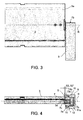
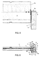
- FIGS. 3 and 4 and FIGS. 5 and 6 show a detail of an exemplary embodiment of the guide device according to the invention in a side view and as an elevation, wherein the guide body 11 in the case of FIGS FIGS. 3 and 4 occupies a first end position within a limited range of motion and in the FIGS. 5 and 6 a second end position.
- the guide body 11 extends over the entire length of the base body 9 and comprises on the side facing away from the base body 9 analogous to conventional guide rails 1 a guide groove 5 for guiding the outstanding on the narrow sides 3a of the slats 3 guide elements 7.
- the range of motion of the guide elements 7 within the respective guide body 11 in the direction of the pivot axes R minimal.
- the guide elements 7 generally include a lamella side flat mounting portion which is riveted to the blade 3 or connected in any other way.
- the area of the guide elements 7 projecting beyond the narrow side 3a of the lamella 3 comprises a generally cylindrical neck 7a and a flange or head 7b formed at the end of the neck 7a, which radially projects beyond the neck 7a.
- Adjacent to the lamella 3, the neck 7a may comprise a small bead 7c or collar as a spacer for specifying the gap width S1 or S2 between the lamella end and the guide body 11.
- the width of the guide groove 5 is in a front, to the slats.
- the narrow point may also be limited to only a portion of the front portion, for example, where the adjacent to the necks 7a edges of the guide body 11 are rounded. Subsequent to the narrow front region, the width of the guide groove 5 widens in a rear section and thus forms a shoulder or stop 11a for the flanges or heads 7b of the guide elements 7. A movement of the guide elements 7 relative to the guide body 11 in the direction of the pivot axes R is not possible or only with minimal play.
- the guide body 11 itself is movable transversely to the guide groove 5 in the direction of the pivot axes R, in particular displaceable and / or pivotable and / or deformable or generally changeable in its position on the base body 9.
- the position of the lamella ends or the position of the guide elements 7 in the direction of the pivot axes R determines the position of the guide body 11 relative to the base body.
- the guide device For example, for this purpose on either side of the guide body 11, excellent narrow longitudinal ribs 13 or flanges having a front abutment surface 13a and a rear abutment surface 13b may be provided be provided, which engage in recessed on the inner sides of the base body 9 wider longitudinal grooves 15.
- the side walls of these longitudinal grooves 15 are delimiting elements on which the abutment surfaces 13a, 13b are in or against the direction of the pivot axes R in displacements of the guide body 11.
- the longitudinal ribs 13 may, for example, have a triangular cross-section, as in the illustrated embodiment, wherein the steep leading edge limits the range of motion when pulling out the guide body 11 from the base body 9 in the direction of the pivot axes R, and the more inclined trailing edge of the longitudinal rib 13 when pushing the guide body 11
- the rib 13 could be formed, for example, as a flange which extends to the back of the guide body 11 and connects flush to this. Accordingly, in this case, the longitudinal grooves 15 may extend to the rear-side inner wall of the base body 9 (not shown).
- the guide body 11 When presented in the FIGS. 3 and 4 is the guide body 11 in its inserted end position.
- the lamellae 3 facing front sides of the guide body 11 and the base body 9 are flush in this position, so that the distance S2 'between the fin ends and the adjacent front of the base body 9 is minimal and just the gap width S2 between the narrow sides 3a of the lamellae 3 and corresponds to the adjacent guide body 11.
- the longitudinal rib 13 could be used as a limiting means when inserting the guide body 11, for example, which faces away from the slats 3 back, which is present upon reaching the end position on the adjacent inner wall of the base body 9 (not shown).
- the arrangement shown is the guide body 11 in the withdrawn end position.
- the distance S2 'between the lamellar ends and the adjacent front side of the base body 9 is greater than the gap width S2 between the narrow sides 3a of the lamellae 3 and the adjacent guide body 11.
- this of course also applies to the distance S1' and the gap width S1 in the other Guide rail 1.
- the base body 9 and / or the guide body 11 have dimensionally stable cross-sections, but are sufficiently flexible in their longitudinal direction, so that their position or shape transversely to their longitudinal direction in the direction of the pivot axes R within certain tolerance limits locally to the respective environment can be adjusted.
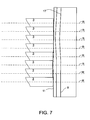
- the base body 9 can therefore be adapted locally to slight curvature or unevenness of the soffit 17 aconcentraussparung.
- the vaults are in FIG. 7 exaggeratedly displayed for better visibility.
- the guide body 11 is able to compensate for such deviating from the line lines due to its flexibility and displaceability of the base body 9 in the direction of the pivot axes R of the slats 3.
- the curvature of the soffit 17 is in FIG. 7 also the adaptation of the guide body 11 to different positions of the fin ends 3a recognizable.
- the base body 9 is an extruded metal, in particular aluminum, and the guide body 11 is an extrusion profile made of plastic.
- additional guide means or securing elements may be provided such as at the two front ends of the base body 9 aufschraubbare or press-in end plates (not shown).
- the guide body 11 could e.g. also have a cross-sectionally C-shaped profile which is mounted on the outside of the base body 9 within predeterminable limits in the direction of the pivot axes R movable, displaceable, pivotable or generally changeable in its position and / or deformable (not shown).
Landscapes
- Engineering & Computer Science (AREA)
- Structural Engineering (AREA)
- Architecture (AREA)
- Civil Engineering (AREA)
- Blinds (AREA)
- Operating, Guiding And Securing Of Roll- Type Closing Members (AREA)
Abstract
Die Vorrichtung zu Führen von Lamellen (3) bei Lamellenstoren umfasst eine Führungsschiene (1) mit einem Basiskörper (9) und einem Führungskörper (11) mit einer Führungsnut (5), in welche an den Schmalseiten (3a) der Lamellen (3) hervorragende Führungselemente (7) eingreifen. Der Führungskörper (11) ist am Basiskörper (9) quer zur Führungsnut (5) verschiebbar gelagert. Die Führungselemente (7) sind entlang der Führungsnuten (5) verschiebbar und um Schwenkachsen R schwenkbar. Sie umfassen Mitnehmer, welche die relative Lage des Führungskörpers (11) so anpassen, dass der Abstand zwischen jedem der Lamellenenden (3a) und dem Führungskörper (11) konstant bleibt.The device for guiding slats (3) in slat blinds comprises a guide rail (1) with a base body (9) and a guide body (11) with a guide groove (5) into which protruding on the narrow sides (3a) of the slats (3) Engage the guide elements (7). The guide body (11) is slidably mounted on the base body (9) transversely to the guide groove (5). The guide elements (7) can be moved along the guide grooves (5) and can be pivoted about pivot axes R. They comprise drivers which adapt the relative position of the guide body (11) so that the distance between each of the lamella ends (3a) and the guide body (11) remains constant.
Description
Gegenstand der Erfindung ist eine Vorrichtung zum Führen von Lamellen bei Lamellenstoren gemäss dem Oberbegriff des Patentanspruchs 1.The invention relates to a device for guiding slats in slat blinds according to the preamble of
Bei Rafflamellenstoren mit seitlichen Führungsschienen, welche die Lamellen beim Öffnen und Schliessen des Behangs innerhalb einer Gebäudeaussparung führen und den Bewegungsspielraum der Lamellen begrenzen, umfassen die Lamellen in der Regel an den Schmalseiten hervorragende Führungselemente, welche im Eingriff mit einer Führungsnut an der jeweils benachbarten Führungsschiene stehen.In Rafflamellenstoren with lateral guide rails, which guide the slats when opening and closing the curtain within a building recess and limit the range of motion of the slats, the slats usually include on the narrow sides outstanding guide elements which are in engagement with a guide groove on the adjacent guide rail ,
Damit die Lamellen in Verschieberichtung des Behangs ungehindert bewegt werden können, ist zwischen den Schmalseiten der Lamellen und den jeweils benachbarten Führungsschienen je ein schmaler Spalt vorgesehen. Aufgrund von Fertigungstoleranzen und unterschiedlichen Temperaturausdehnungskoeffizienten können die Spaltbreiten zum Teil unerwünscht gross sein. Damit ein einwandfreier Betrieb der Store möglich ist, muss den Lamellen zwischen den beiden Führungsschienen ausreichend Spiel zugestanden werden. Durch eine Bewegung der Lamellen in ihrer Längsrichtung bzw. quer zur Verschieberichtung des Behangs kann sich die Spaltbreite auf jeder der beiden Seiten zusätzlich vergrössern.Thus, the slats can be moved unhindered in the direction of displacement of the curtain, is provided between the narrow sides of the slats and the respective adjacent guide rails depending on a narrow gap. Due to manufacturing tolerances and different coefficients of thermal expansion, the gap widths can sometimes be undesirably large. To ensure proper operation of the store, the slats between the two guide rails must be allowed sufficient clearance. By a movement of the slats in their longitudinal direction or transversely to the direction of displacement of the curtain, the gap width on each of the two sides can additionally increase.
Solche seitlichen Spalte sind unerwünscht, da sie einerseits einer zufriedenstellenden Abdunkelung eines Raumes entgegenstehen und andererseits nur noch einen ungenügenden Sichtschutz durch den Behang ermöglichen.Such lateral gaps are undesirable, since on the one hand they oppose a satisfactory darkening of a room and on the other hand only allow insufficient privacy through the curtain.
Eine Aufgabe der vorliegenden Erfindung ist es deshalb, eine Vorrichtung zum Führen von Lamellen bei Lamellenstoren zu schaffen, welche die genannten Nachteile ohne Beeinträchtigung anderer Funktionen minimiert.An object of the present invention is therefore to provide a device for guiding slats in slatted blinds, which minimizes the aforementioned disadvantages without affecting other functions.
Diese Aufgabe wird gelöst durch eine Vorrichtung zum Führen von Lamellen gemäss den Merkmalen des Patentanspruchs 1.This object is achieved by a device for guiding slats according to the features of
Anhand einiger Figuren wird die Erfindung im Folgenden näher beschrieben. Dabei zeigen
Figur 1- einen schematischen Querschnitt einer Store gemäss Stand der Technik,
- Figur 2
- einen perspektivisch dargestellten Ausschnitt einer Rafflamellenstore im Bereich eines schmalseitigen Lamellenendes,
Figur 3- eine Frontansicht des Ausschnittes der Rafflamellenstore aus
Figur 1 in einer ersten Funktionsstellung, - Figur 4
- eine Aufsicht des Ausschnittes der Rafflamellenstore aus
Figur 1 in der ersten Funktionsstellung, Figur 5- eine Frontansicht des Ausschnittes der Rafflamellenstore aus
Figur 1 in einer zweiten Funktionsstellung, - Figur 6
- eine Aufsicht des Ausschnittes der Rafflamellenstore aus
Figur 1 in der zweiten Funktionsstellung, Figur 7- eine Anordnung einer Führungsvorrichtung an einer leicht gewölbten Laibung.
- FIG. 1
- a schematic cross section of a store according to the prior art,
- FIG. 2
- a detail of a Rafflamellenstore shown in perspective in the region of a narrow-side fin end,
- FIG. 3
- a front view of the clipping of the Rafflamellenstore
FIG. 1 in a first functional position, - FIG. 4
- a top view of the clipping of the Rafflamellenstore
FIG. 1 in the first functional position, - FIG. 5
- a front view of the clipping of the Rafflamellenstore
FIG. 1 in a second functional position, - FIG. 6
- a top view of the clipping of the Rafflamellenstore
FIG. 1 in the second functional position, - FIG. 7
- an arrangement of a guide device on a slightly curved soffit.
Die
Bei der Darstellung in den
Alternativ zur Längsrippe 13 könnte beim Einschieben des Führungskörpers 11 z.B. auch dessen von den Lamellen 3 abgewandte Rückseite als Begrenzungsmittel genutzt werden, welches beim Erreichen der Endlage an der benachbarten Innenwand des Basiskörpers 9 ansteht (nicht dargestellt). Bei der in den
Vorzugsweise ist der Basiskörper 9 ein Strangpressprofil aus Metall, insbesondere aus Aluminium, und der Führungskörper 11 ein Extrusionsprofil aus Kunststoff. Zum Verhindern einer Verschiebung des Führungskörpers 11 in Längsrichtung relativ zum Basiskörper 9 nach der Montage einer Store können zusätzliche Führungsmittel oder Sicherungselemente vorgesehen sein wie z.B. an den beiden stirnseitigen Enden des Basiskörpers 9 aufschraubbare oder einpressbare Endplatten (nicht dargestellt).Preferably, the
Alternativ zur dargestellten Ausführungsform der Führungsschiene 1 könnte der Führungskörper 11 z.B. auch ein im Querschnitt C-förmiges Profil aufweisen welches an der Aussenseite des Basiskörpers 9 innerhalb vorgebbarer Grenzen in Richtung der Schwenkachsen R bewegbar, verschiebbar, verschwenkbar bzw. allgemein in seiner Lage veränderbar und/oder verformbar gelagert ist (nicht dargestellt).As an alternative to the illustrated embodiment of the
Claims (10)
Applications Claiming Priority (1)
| Application Number | Priority Date | Filing Date | Title |
|---|---|---|---|
| CH02068/10A CH704200A1 (en) | 2010-12-10 | 2010-12-10 | Device for guiding slats in venetian blinds. |
Publications (3)
| Publication Number | Publication Date |
|---|---|
| EP2463473A2 true EP2463473A2 (en) | 2012-06-13 |
| EP2463473A3 EP2463473A3 (en) | 2015-05-27 |
| EP2463473B1 EP2463473B1 (en) | 2016-02-10 |
Family
ID=45218614
Family Applications (1)
| Application Number | Title | Priority Date | Filing Date |
|---|---|---|---|
| EP11405361.4A Active EP2463473B1 (en) | 2010-12-10 | 2011-11-28 | Device for guiding lamellae of lamelar blinds |
Country Status (3)
| Country | Link |
|---|---|
| EP (1) | EP2463473B1 (en) |
| CH (1) | CH704200A1 (en) |
| ES (1) | ES2573753T3 (en) |
Family Cites Families (6)
| Publication number | Priority date | Publication date | Assignee | Title |
|---|---|---|---|---|
| DE59403909D1 (en) * | 1993-03-17 | 1997-10-09 | Griesser Ag | Louvre blind |
| EP0621391B1 (en) * | 1993-04-17 | 1998-04-22 | Griesser Holding Ag | Venetian blind |
| DE9412811U1 (en) * | 1994-08-09 | 1995-12-07 | Westmont Technik GmbH & Co. KG, 40474 Düsseldorf | Sun protection device, in particular for translucent sun roofs |
| CH691916A5 (en) * | 1997-01-15 | 2001-11-30 | Nyffenegger Storenfabrik Ag | Device with an adjustable body for protection against light and / or weathering and / or burglary and / or redirecting light. |
| EP0890703B1 (en) * | 1997-07-08 | 2004-04-28 | Nyffenegger Storenfabrik AG | Lamellar blind and building with a lamellar blind |
| ATE300658T1 (en) * | 1998-12-23 | 2005-08-15 | Nyffenegger Storenfabrik Ag | DEVICE FOR PROTECTION AGAINST LIGHT AND/OR WEATHER AND/OR BURGLARY |
-
2010
- 2010-12-10 CH CH02068/10A patent/CH704200A1/en not_active Application Discontinuation
-
2011
- 2011-11-28 ES ES11405361.4T patent/ES2573753T3/en active Active
- 2011-11-28 EP EP11405361.4A patent/EP2463473B1/en active Active
Non-Patent Citations (1)
| Title |
|---|
| None |
Also Published As
| Publication number | Publication date |
|---|---|
| EP2463473A3 (en) | 2015-05-27 |
| EP2463473B1 (en) | 2016-02-10 |
| ES2573753T3 (en) | 2016-06-09 |
| CH704200A1 (en) | 2012-06-15 |
Similar Documents
| Publication | Publication Date | Title |
|---|---|---|
| DE60200510T2 (en) | Guide rail assembly for a tilt gate | |
| WO2008046610A2 (en) | Extruded hollow chamber profile for windows or doors | |
| EP2348187A2 (en) | Roller blind box | |
| DE102008012202A1 (en) | Roof window roller blind with clamping device | |
| DE102014103043A1 (en) | guiding device | |
| DE102019215548B4 (en) | Drive system for a movable roof part of a roof system of a motor vehicle | |
| EP2405095B1 (en) | Door seal with fixing element | |
| EP3112577A1 (en) | Drop-down seal | |
| DE202016102808U1 (en) | Furniture with a movable on a running profile sliding element and a guide device | |
| EP2354431B1 (en) | Roller blind box with guide rails | |
| EP2463473B1 (en) | Device for guiding lamellae of lamelar blinds | |
| WO2015051985A1 (en) | Sliding door or sliding window | |
| EP2759666B1 (en) | Fitting with a profile element | |
| AT15365U1 (en) | glazing system | |
| WO2016131476A1 (en) | Magnetic seal for fast-action portals | |
| DE202012011998U1 (en) | Sliding door or window assembly with a frame part and sliding door or window wings therein | |
| DE202009012189U1 (en) | Roller curtain | |
| EP3085281B1 (en) | Sliding element for displaceable storage of a curtain or a tarpaulin | |
| WO2006042609A1 (en) | Profiled element | |
| DE102012100153A1 (en) | Side guide for shutters and blinds | |
| EP3530861A1 (en) | Horizontal frame section for a sliding door and/or sliding window frame, sliding door and/or sliding window frame and sliding door and/or sliding window frame system | |
| DE202009008455U1 (en) | Guide rail and device for covering building openings | |
| EP3489451B1 (en) | Connection of a roller shutter box with a frame | |
| DE2848094A1 (en) | Vehicle sunroof with interlocking C=section shutters - follows roof camber with one shutter inclined relative to lateral tracks | |
| EP1460214B1 (en) | Plastic espagnolette |
Legal Events
| Date | Code | Title | Description |
|---|---|---|---|
| PUAI | Public reference made under article 153(3) epc to a published international application that has entered the european phase |
Free format text: ORIGINAL CODE: 0009012 |
|
| AK | Designated contracting states |
Kind code of ref document: A2 Designated state(s): AL AT BE BG CH CY CZ DE DK EE ES FI FR GB GR HR HU IE IS IT LI LT LU LV MC MK MT NL NO PL PT RO RS SE SI SK SM TR |
|
| AX | Request for extension of the european patent |
Extension state: BA ME |
|
| PUAL | Search report despatched |
Free format text: ORIGINAL CODE: 0009013 |
|
| AK | Designated contracting states |
Kind code of ref document: A3 Designated state(s): AL AT BE BG CH CY CZ DE DK EE ES FI FR GB GR HR HU IE IS IT LI LT LU LV MC MK MT NL NO PL PT RO RS SE SI SK SM TR |
|
| AX | Request for extension of the european patent |
Extension state: BA ME |
|
| RIC1 | Information provided on ipc code assigned before grant |
Ipc: E06B 9/327 20060101AFI20150421BHEP |
|
| 17P | Request for examination filed |
Effective date: 20150620 |
|
| RBV | Designated contracting states (corrected) |
Designated state(s): AL AT BE BG CH CY CZ DE DK EE ES FI FR GB GR HR HU IE IS IT LI LT LU LV MC MK MT NL NO PL PT RO RS SE SI SK SM TR |
|
| GRAP | Despatch of communication of intention to grant a patent |
Free format text: ORIGINAL CODE: EPIDOSNIGR1 |
|
| INTG | Intention to grant announced |
Effective date: 20151002 |
|
| GRAS | Grant fee paid |
Free format text: ORIGINAL CODE: EPIDOSNIGR3 |
|
| GRAA | (expected) grant |
Free format text: ORIGINAL CODE: 0009210 |
|
| AK | Designated contracting states |
Kind code of ref document: B1 Designated state(s): AL AT BE BG CH CY CZ DE DK EE ES FI FR GB GR HR HU IE IS IT LI LT LU LV MC MK MT NL NO PL PT RO RS SE SI SK SM TR |
|
| REG | Reference to a national code |
Ref country code: GB Ref legal event code: FG4D Free format text: NOT ENGLISH |
|
| REG | Reference to a national code |
Ref country code: AT Ref legal event code: REF Ref document number: 774749 Country of ref document: AT Kind code of ref document: T Effective date: 20160215 Ref country code: CH Ref legal event code: EP |
|
| REG | Reference to a national code |
Ref country code: CH Ref legal event code: NV Representative=s name: GACHNANG AG PATENTANWAELTE, CH |
|
| REG | Reference to a national code |
Ref country code: IE Ref legal event code: FG4D Free format text: LANGUAGE OF EP DOCUMENT: GERMAN |
|
| REG | Reference to a national code |
Ref country code: DE Ref legal event code: R096 Ref document number: 502011008847 Country of ref document: DE |
|
| REG | Reference to a national code |
Ref country code: ES Ref legal event code: FG2A Ref document number: 2573753 Country of ref document: ES Kind code of ref document: T3 Effective date: 20160609 |
|
| REG | Reference to a national code |
Ref country code: LT Ref legal event code: MG4D |
|
| REG | Reference to a national code |
Ref country code: NL Ref legal event code: MP Effective date: 20160210 |
|
| PG25 | Lapsed in a contracting state [announced via postgrant information from national office to epo] |
Ref country code: NO Free format text: LAPSE BECAUSE OF FAILURE TO SUBMIT A TRANSLATION OF THE DESCRIPTION OR TO PAY THE FEE WITHIN THE PRESCRIBED TIME-LIMIT Effective date: 20160510 Ref country code: HR Free format text: LAPSE BECAUSE OF FAILURE TO SUBMIT A TRANSLATION OF THE DESCRIPTION OR TO PAY THE FEE WITHIN THE PRESCRIBED TIME-LIMIT Effective date: 20160210 Ref country code: GR Free format text: LAPSE BECAUSE OF FAILURE TO SUBMIT A TRANSLATION OF THE DESCRIPTION OR TO PAY THE FEE WITHIN THE PRESCRIBED TIME-LIMIT Effective date: 20160511 Ref country code: FI Free format text: LAPSE BECAUSE OF FAILURE TO SUBMIT A TRANSLATION OF THE DESCRIPTION OR TO PAY THE FEE WITHIN THE PRESCRIBED TIME-LIMIT Effective date: 20160210 |
|
| PG25 | Lapsed in a contracting state [announced via postgrant information from national office to epo] |
Ref country code: IS Free format text: LAPSE BECAUSE OF FAILURE TO SUBMIT A TRANSLATION OF THE DESCRIPTION OR TO PAY THE FEE WITHIN THE PRESCRIBED TIME-LIMIT Effective date: 20160610 Ref country code: SE Free format text: LAPSE BECAUSE OF FAILURE TO SUBMIT A TRANSLATION OF THE DESCRIPTION OR TO PAY THE FEE WITHIN THE PRESCRIBED TIME-LIMIT Effective date: 20160210 Ref country code: RS Free format text: LAPSE BECAUSE OF FAILURE TO SUBMIT A TRANSLATION OF THE DESCRIPTION OR TO PAY THE FEE WITHIN THE PRESCRIBED TIME-LIMIT Effective date: 20160210 Ref country code: NL Free format text: LAPSE BECAUSE OF FAILURE TO SUBMIT A TRANSLATION OF THE DESCRIPTION OR TO PAY THE FEE WITHIN THE PRESCRIBED TIME-LIMIT Effective date: 20160210 Ref country code: PT Free format text: LAPSE BECAUSE OF FAILURE TO SUBMIT A TRANSLATION OF THE DESCRIPTION OR TO PAY THE FEE WITHIN THE PRESCRIBED TIME-LIMIT Effective date: 20160613 Ref country code: PL Free format text: LAPSE BECAUSE OF FAILURE TO SUBMIT A TRANSLATION OF THE DESCRIPTION OR TO PAY THE FEE WITHIN THE PRESCRIBED TIME-LIMIT Effective date: 20160210 Ref country code: LT Free format text: LAPSE BECAUSE OF FAILURE TO SUBMIT A TRANSLATION OF THE DESCRIPTION OR TO PAY THE FEE WITHIN THE PRESCRIBED TIME-LIMIT Effective date: 20160210 Ref country code: LV Free format text: LAPSE BECAUSE OF FAILURE TO SUBMIT A TRANSLATION OF THE DESCRIPTION OR TO PAY THE FEE WITHIN THE PRESCRIBED TIME-LIMIT Effective date: 20160210 |
|
| PG25 | Lapsed in a contracting state [announced via postgrant information from national office to epo] |
Ref country code: EE Free format text: LAPSE BECAUSE OF FAILURE TO SUBMIT A TRANSLATION OF THE DESCRIPTION OR TO PAY THE FEE WITHIN THE PRESCRIBED TIME-LIMIT Effective date: 20160210 Ref country code: DK Free format text: LAPSE BECAUSE OF FAILURE TO SUBMIT A TRANSLATION OF THE DESCRIPTION OR TO PAY THE FEE WITHIN THE PRESCRIBED TIME-LIMIT Effective date: 20160210 |
|
| REG | Reference to a national code |
Ref country code: DE Ref legal event code: R097 Ref document number: 502011008847 Country of ref document: DE |
|
| REG | Reference to a national code |
Ref country code: FR Ref legal event code: PLFP Year of fee payment: 6 |
|
| PG25 | Lapsed in a contracting state [announced via postgrant information from national office to epo] |
Ref country code: SM Free format text: LAPSE BECAUSE OF FAILURE TO SUBMIT A TRANSLATION OF THE DESCRIPTION OR TO PAY THE FEE WITHIN THE PRESCRIBED TIME-LIMIT Effective date: 20160210 Ref country code: SK Free format text: LAPSE BECAUSE OF FAILURE TO SUBMIT A TRANSLATION OF THE DESCRIPTION OR TO PAY THE FEE WITHIN THE PRESCRIBED TIME-LIMIT Effective date: 20160210 Ref country code: CZ Free format text: LAPSE BECAUSE OF FAILURE TO SUBMIT A TRANSLATION OF THE DESCRIPTION OR TO PAY THE FEE WITHIN THE PRESCRIBED TIME-LIMIT Effective date: 20160210 Ref country code: RO Free format text: LAPSE BECAUSE OF FAILURE TO SUBMIT A TRANSLATION OF THE DESCRIPTION OR TO PAY THE FEE WITHIN THE PRESCRIBED TIME-LIMIT Effective date: 20160210 |
|
| PLBE | No opposition filed within time limit |
Free format text: ORIGINAL CODE: 0009261 |
|
| STAA | Information on the status of an ep patent application or granted ep patent |
Free format text: STATUS: NO OPPOSITION FILED WITHIN TIME LIMIT |
|
| 26N | No opposition filed |
Effective date: 20161111 |
|
| PG25 | Lapsed in a contracting state [announced via postgrant information from national office to epo] |
Ref country code: BE Free format text: LAPSE BECAUSE OF NON-PAYMENT OF DUE FEES Effective date: 20161130 Ref country code: BG Free format text: LAPSE BECAUSE OF FAILURE TO SUBMIT A TRANSLATION OF THE DESCRIPTION OR TO PAY THE FEE WITHIN THE PRESCRIBED TIME-LIMIT Effective date: 20160510 Ref country code: SI Free format text: LAPSE BECAUSE OF FAILURE TO SUBMIT A TRANSLATION OF THE DESCRIPTION OR TO PAY THE FEE WITHIN THE PRESCRIBED TIME-LIMIT Effective date: 20160210 |
|
| GBPC | Gb: european patent ceased through non-payment of renewal fee |
Effective date: 20161128 |
|
| REG | Reference to a national code |
Ref country code: IE Ref legal event code: MM4A |
|
| PG25 | Lapsed in a contracting state [announced via postgrant information from national office to epo] |
Ref country code: LU Free format text: LAPSE BECAUSE OF NON-PAYMENT OF DUE FEES Effective date: 20161130 |
|
| REG | Reference to a national code |
Ref country code: FR Ref legal event code: PLFP Year of fee payment: 7 |
|
| PG25 | Lapsed in a contracting state [announced via postgrant information from national office to epo] |
Ref country code: GB Free format text: LAPSE BECAUSE OF NON-PAYMENT OF DUE FEES Effective date: 20161128 Ref country code: IE Free format text: LAPSE BECAUSE OF NON-PAYMENT OF DUE FEES Effective date: 20161128 |
|
| REG | Reference to a national code |
Ref country code: BE Ref legal event code: MM Effective date: 20161130 |
|
| PG25 | Lapsed in a contracting state [announced via postgrant information from national office to epo] |
Ref country code: HU Free format text: LAPSE BECAUSE OF FAILURE TO SUBMIT A TRANSLATION OF THE DESCRIPTION OR TO PAY THE FEE WITHIN THE PRESCRIBED TIME-LIMIT; INVALID AB INITIO Effective date: 20111128 Ref country code: CY Free format text: LAPSE BECAUSE OF FAILURE TO SUBMIT A TRANSLATION OF THE DESCRIPTION OR TO PAY THE FEE WITHIN THE PRESCRIBED TIME-LIMIT Effective date: 20160210 |
|
| PG25 | Lapsed in a contracting state [announced via postgrant information from national office to epo] |
Ref country code: TR Free format text: LAPSE BECAUSE OF FAILURE TO SUBMIT A TRANSLATION OF THE DESCRIPTION OR TO PAY THE FEE WITHIN THE PRESCRIBED TIME-LIMIT Effective date: 20160210 Ref country code: MC Free format text: LAPSE BECAUSE OF FAILURE TO SUBMIT A TRANSLATION OF THE DESCRIPTION OR TO PAY THE FEE WITHIN THE PRESCRIBED TIME-LIMIT Effective date: 20160210 Ref country code: MK Free format text: LAPSE BECAUSE OF FAILURE TO SUBMIT A TRANSLATION OF THE DESCRIPTION OR TO PAY THE FEE WITHIN THE PRESCRIBED TIME-LIMIT Effective date: 20160210 |
|
| PG25 | Lapsed in a contracting state [announced via postgrant information from national office to epo] |
Ref country code: MT Free format text: LAPSE BECAUSE OF FAILURE TO SUBMIT A TRANSLATION OF THE DESCRIPTION OR TO PAY THE FEE WITHIN THE PRESCRIBED TIME-LIMIT Effective date: 20160210 |
|
| PG25 | Lapsed in a contracting state [announced via postgrant information from national office to epo] |
Ref country code: AL Free format text: LAPSE BECAUSE OF FAILURE TO SUBMIT A TRANSLATION OF THE DESCRIPTION OR TO PAY THE FEE WITHIN THE PRESCRIBED TIME-LIMIT Effective date: 20160210 |
|
| REG | Reference to a national code |
Ref country code: CH Ref legal event code: PK Free format text: BERICHTIGUNGEN |
|
| REG | Reference to a national code |
Ref country code: CH Ref legal event code: U11 Free format text: ST27 STATUS EVENT CODE: U-0-0-U10-U11 (AS PROVIDED BY THE NATIONAL OFFICE) Effective date: 20251201 |
|
| PGFP | Annual fee paid to national office [announced via postgrant information from national office to epo] |
Ref country code: DE Payment date: 20251118 Year of fee payment: 15 |
|
| PGFP | Annual fee paid to national office [announced via postgrant information from national office to epo] |
Ref country code: AT Payment date: 20251117 Year of fee payment: 15 |
|
| PGFP | Annual fee paid to national office [announced via postgrant information from national office to epo] |
Ref country code: IT Payment date: 20251128 Year of fee payment: 15 |
|
| PGFP | Annual fee paid to national office [announced via postgrant information from national office to epo] |
Ref country code: FR Payment date: 20251125 Year of fee payment: 15 |
|
| PGFP | Annual fee paid to national office [announced via postgrant information from national office to epo] |
Ref country code: CH Payment date: 20251201 Year of fee payment: 15 |
|
| PGFP | Annual fee paid to national office [announced via postgrant information from national office to epo] |
Ref country code: ES Payment date: 20251216 Year of fee payment: 15 |