EP2463527A2 - Procédé de réparation de conduite de mesure de pompe à jet - Google Patents
Procédé de réparation de conduite de mesure de pompe à jet Download PDFInfo
- Publication number
- EP2463527A2 EP2463527A2 EP11192764A EP11192764A EP2463527A2 EP 2463527 A2 EP2463527 A2 EP 2463527A2 EP 11192764 A EP11192764 A EP 11192764A EP 11192764 A EP11192764 A EP 11192764A EP 2463527 A2 EP2463527 A2 EP 2463527A2
- Authority
- EP
- European Patent Office
- Prior art keywords
- measurement pipe
- pipe
- cut
- jet pump
- measurement
- Prior art date
- Legal status (The legal status is an assumption and is not a legal conclusion. Google has not performed a legal analysis and makes no representation as to the accuracy of the status listed.)
- Granted
Links
Images


Classifications
-
- G—PHYSICS
- G21—NUCLEAR PHYSICS; NUCLEAR ENGINEERING
- G21C—NUCLEAR REACTORS
- G21C15/00—Cooling arrangements within the pressure vessel containing the core; Selection of specific coolants
- G21C15/24—Promoting flow of the coolant
- G21C15/243—Promoting flow of the coolant for liquids
- G21C15/25—Promoting flow of the coolant for liquids using jet pumps
-
- F—MECHANICAL ENGINEERING; LIGHTING; HEATING; WEAPONS; BLASTING
- F04—POSITIVE - DISPLACEMENT MACHINES FOR LIQUIDS; PUMPS FOR LIQUIDS OR ELASTIC FLUIDS
- F04F—PUMPING OF FLUID BY DIRECT CONTACT OF ANOTHER FLUID OR BY USING INERTIA OF FLUID TO BE PUMPED; SIPHONS
- F04F5/00—Jet pumps, i.e. devices in which flow is induced by pressure drop caused by velocity of another fluid flow
- F04F5/54—Installations characterised by use of jet pumps, e.g. combinations of two or more jet pumps of different type
-
- G—PHYSICS
- G21—NUCLEAR PHYSICS; NUCLEAR ENGINEERING
- G21C—NUCLEAR REACTORS
- G21C17/00—Monitoring; Testing ; Maintaining
- G21C17/017—Inspection or maintenance of pipe-lines or tubes in nuclear installations
-
- G—PHYSICS
- G21—NUCLEAR PHYSICS; NUCLEAR ENGINEERING
- G21C—NUCLEAR REACTORS
- G21C19/00—Arrangements for treating, for handling, or for facilitating the handling of, fuel or other materials which are used within the reactor, e.g. within its pressure vessel
- G21C19/14—Arrangements for treating, for handling, or for facilitating the handling of, fuel or other materials which are used within the reactor, e.g. within its pressure vessel characterised by their adaptation for use with horizontal channels in the reactor core
-
- G—PHYSICS
- G21—NUCLEAR PHYSICS; NUCLEAR ENGINEERING
- G21C—NUCLEAR REACTORS
- G21C17/00—Monitoring; Testing ; Maintaining
- G21C17/10—Structural combination of fuel element, control rod, reactor core, or moderator structure with sensitive instruments, e.g. for measuring radioactivity, strain
-
- Y—GENERAL TAGGING OF NEW TECHNOLOGICAL DEVELOPMENTS; GENERAL TAGGING OF CROSS-SECTIONAL TECHNOLOGIES SPANNING OVER SEVERAL SECTIONS OF THE IPC; TECHNICAL SUBJECTS COVERED BY FORMER USPC CROSS-REFERENCE ART COLLECTIONS [XRACs] AND DIGESTS
- Y02—TECHNOLOGIES OR APPLICATIONS FOR MITIGATION OR ADAPTATION AGAINST CLIMATE CHANGE
- Y02E—REDUCTION OF GREENHOUSE GAS [GHG] EMISSIONS, RELATED TO ENERGY GENERATION, TRANSMISSION OR DISTRIBUTION
- Y02E30/00—Energy generation of nuclear origin
- Y02E30/30—Nuclear fission reactors
-
- Y—GENERAL TAGGING OF NEW TECHNOLOGICAL DEVELOPMENTS; GENERAL TAGGING OF CROSS-SECTIONAL TECHNOLOGIES SPANNING OVER SEVERAL SECTIONS OF THE IPC; TECHNICAL SUBJECTS COVERED BY FORMER USPC CROSS-REFERENCE ART COLLECTIONS [XRACs] AND DIGESTS
- Y10—TECHNICAL SUBJECTS COVERED BY FORMER USPC
- Y10T—TECHNICAL SUBJECTS COVERED BY FORMER US CLASSIFICATION
- Y10T29/00—Metal working
- Y10T29/49—Method of mechanical manufacture
- Y10T29/49718—Repairing
- Y10T29/49732—Repairing by attaching repair preform, e.g., remaking, restoring, or patching
- Y10T29/49734—Repairing by attaching repair preform, e.g., remaking, restoring, or patching and removing damaged material
- Y10T29/49735—Mechanically attaching preform with separate fastener
Definitions
- Embodiments described herein relate generally to a jet pump measurement pipe repair method for repairing a measurement pipe provided in a diffuser of a jet pump in a boiling water reactor.
- a conventional boiling water reactor adopts a so-called jet pump system obtained by combining recirculation pumps installed outside a reactor pressure vessel and jet pumps installed inside the reactor pressure vessel for the purpose of increasing power density.
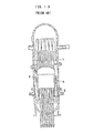
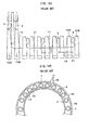
- a plurality of jet pumps 4 are arranged at equal intervals in the circumferential direction between a rector pressure vessel 1 and a shroud 2 which are vertically installed in a downcomer part 3.
- the jet pumps 4 each have a riser pipe 5.
- the riser pipe 5 is fixed to the rector pressure vessel 1 and introduces coolant supplied from a recirculation inlet nozzle 6 of a recirculation pump into the reactor pressure vessel.
- a pair of elbows 7A and 7B are connected to the upper part of the riser pipe 5 through a transition piece 14.
- a pair of inlet throats 9A and 9B are connected respectively to the pair of elbows 7A and 7B through a pair of mixing nozzles 8A and 8B.
- Diffusers 10A and 10B are connected respectively to the pair of inlet throats 9A and 9B.
- inlet throats 9A, 9B and diffusers 10A, 10B are collectively referred to as “inlet throat 9" and "diffuser 10" when they are not differentiated.
- Measurement of the flow rate of the jet pumps 4 during normal operation is important for power control of a nuclear power plant.
- measurement pipes 11 are provided at the upper and lower parts of each of the diffusers 10A and 10B.
- the measurement pipes 11 are used to measure the difference in the static pressure between the upper and lower parts of the diffuser 10 during operation, and the obtained measurement value is calibrated with a calibration value that has previously been measured before the use of the plant, whereby the flow rate of the jet pumps 4 are calculated.
- Each of the measurement pipes 11 is welded to static pressure holes formed at the upper and lower parts of the diffuser 10 and is welded to be supported by blocks 12 and a support 13 ( FIG. 15 ) which are supporting members fixed to the diffuser 10.
- the measurement pipes 11 are arranged in the lower part of the jet pumps 4 in a complicated manner and are connected to pipes outside the reactor through jet pump measurement nozzles 15.
- the jet pump measurement nozzles 15 are provided at two symmetrical positions in a horizontal cross-section of the reactor pressure vessel 1.
- the jet pumps 4 having the configuration described above are exposed to more severe conditions than other equipment because of a high temperature of about 300°C and flow of a high speed/large flow rate cooling water pumped from a not-illustrated recirculation pumps. Therefore, a large load is applied to each of the members of the jet pumps 4.
- the measurement pipes 11 is subject to sever stress as they are affected, either directly or through the blocks 12 and the supports 13, by the fluid vibration generated by the flow of the high speed/large flow rate cooling water of the diffuser 10 pumped from the recirculation pumps. As a result, several pipe breakages have occurred so far. Such a breakage of the measurement pipes 11 makes it impossible to measure the flow rate of the jet pumps 4, posing a problem for the power control of the reactor, so that repair work must be conducted quickly.
- the measurement pipes 11 are arranged in a narrow annular space 16 between the reactor pressure vessel 1 and the shroud 2.
- the riser pipes 5, inlet throats 9, and the like are arranged above the measurement pipes 11 as illustrated in FIG. 14 .
- the horizontally extending part ( FIG. 15 ) of the measurement pipe 11 near the supports 13 is closest to the shroud 2, and the interval between the measurement pipe 11 and the shroud 2 at this part is as small as less than 150 mm.
- the intermediate body part of the shroud 2 overhangs the horizontally extending part of the measurement pipe 11. This limits much the shape and size of a repair tool for the measurement pipe 11 and a repair method applied to the measurement pipe 11, making the repair work difficult to carry out.
- the site around the measurement pipes 11 are high-radiation area, so that it is very difficult for workers to access the part to be repaired. Therefore, that under present circumstance, there is no alternative way but to remotely carry out the repair work for the measurement pipes 11 from just above the reactor core underwater.
- Patent Document 1 Japanese Patent No. 4,298,527
- Patent Document 2 Japanese Patent Application Laid-Open Publication No. 2004-209515
- the present invention has been made in view of the above situation, and an object thereof is to provide a jet pump measurement pipe repair method capable of coping with a breakage event occurring at the lower part of a jet pump at which a measurement pipe extends in the horizontal direction underwater.
- a jet pump measurement pipe repair method repairs a breakage part of a measurement pipe horizontally fixed to a lower part of a jet pump provided in reactor water in a reactor pressure vessel.
- the method includes a cutting/removing step of cutting and removing the measurement pipe including the breakage part; a retaining step of retaining a connection pipe for connecting a remaining measurement pipe on the jet pump by means of a clamp; and a connecting step of connecting ends of the remaining measurement pipe by means of the connection pipe.
- FIG. 1 is a flowchart illustrating a first embodiment of the jet pump measurement pipe repair method according to the present invention. This flowchart is a repair process flowchart applied upon occurrence of a breakage of the horizontal part of the measurement pipe 11.
- the repair method according to the present embodiment roughly includes step S1 of cutting off and removing the measurement pipe 11 and the support 13, step S2 of attaching a clamp, and step S3 of connecting the measurement pipe 11.
- step S1 a cut-away device used in step S1 will be described.
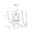
- FIG. 2 is a perspective view schematically illustrating a cut-away device used in the first embodiment and the measurement pipe whose horizontal part has been broken.
- FIG. 3A is a side view illustrating the pipe breakage part side of a cut-away device used in the first embodiment.
- FIG. 3B is a front view of a cutting section of the cut-away device used in the first embodiment.
- FIG. 3C is a front view of a gripping tool of the cut-away device used in the first embodiment.
- FIG. 4A is a side view of another cut-away device used in the first embodiment as viewed from the opposite side of the pipe breakage part.
- FIG. 4B is a front view of another gripping tool of the another cut-away device used in the first embodiment as viewed from the opposite side of the pipe breakage part.
- FIG. 5A is a front view of a cut-away device for support cut-off used in the first embodiment.
- FIG. 5B is a front view of a cutting section of the cut-away device for support cut-off used in the first embodiment.
- FIG. 5C is a front view of a guide of the cut-away device for support cut-off used in the first embodiment. Note that the cut-away devices illustrated in FIGS. 2 and 3 are assumed to be the same although the outer shapes thereof slightly differ from each other on the drawings.
- a cut-away device 24 has a guide section 25 for guiding the broken measurement pipe 11 to be cut, a gripping tool 26 for gripping the measurement pipe 11 guided by the guide part 25, and a cutting section 27 for cutting the measurement pipe 11 near the portion gripped by the gripping tool 26.
- the cut-away device 24 is further provided with a hoisting tool 20 capable of moving up and down in the reactor.
- the hoisting tool 20 is used to move the cut-away device 24 to the breakage part of the measurement pipe 11 with the surrounding around the cut-away device 24 checked with a remote camera, etc.
- the cut-away device 24 has a thickness of as small as 100 mm or less, making it easy for the cut-away device to move down to the breakage part of the measurement pipe 11, and enabling the cutting work in a narrow portion between the shroud 2 and the diffuser 10.
- another cut-away device 24a has a guide section 25a for guiding the measurement pipe 11, a gripping tool 26a for gripping the measurement pipe 11 guided by the guide part 25a, and a cutting section 27a for cutting the measurement pipe 11 near the portion gripped by the gripping tool 26a.
- a cut-away device 24b for cutting the support 13 has a guide section 25b for guiding the support 13, a gripping tool 26b for gripping the support 13 guided by the guide part 25b, and a cutting section 27b for cutting the support 13 near the portion gripped by the gripping tool 26b.
- the present embodiment has two types of cut-away devices 24 and 24a ( FIGS. 3 and 4 ) for cutting away the measurement pipe 11 and has one cut-away device 24b ( FIG. 5 ) for cutting away the support 13.
- These cut-away devices 24, 24a, and 24b have the guide sections 25, 25a, and 25b having different shapes from one another and gripping tools 26, 26a, and 26b each formed into a scissor-like shape so as to grip the measurement pipe 11 or the support 13.
- the use of these cut-away devices 24, 24a, and 24b allows cutting operation to be performed at an accurate position in a stable posture with respect to the measurement pipe 11 or the support 13.
- step S1 of cutting the measurement pipe 11 and the support 13 will be described.
- step S1a the cut-away devices 24 or 24b illustrated in FIGS. 2 , 5A, 5B, and 5C is set to the support 13 of the measurement pipe 11. Subsequently, in step S1b, the gripping tools 26 or 26b is used to grip the measurement pipe 11 and the support 13. Further, in step S1c, the measurement pipe 11 and the support 13 are cut by the cutting sections 27 or 27b of the cut-away devices 24 or 24b. After that, the cut parts of the measurement pipe 11 and the support 13 are collected.
- step S1 the cut-away devices 24 or 24b is set to the support 13, the gripping tools 26 or 26b of the cut-away device 24 or 24b is used to grip the measurement pipe 11 and the support 13, respectively, and the measurement pipe 11 and the support 13 are cut respectively by the cutting sections 27 or 27b, followed by collection of the cut parts of the measurement pipe 11 and the support 13.
- the cut-away device 24 or 24b collects the cut samples (measurement pipe 11 and the support 13) while gripping them by the gripping tools 26 or 26b.
- the gripping tools 26 or 26b which are normally driven by the air supply, are each provided with an elasticity imparting member such as a spring as an auxiliary function. Thus, even if the air supply is interrupted, the gripping tools can grip the cut samples by the elastic force of the spring for collection without dropping them in the reactor.
- the cutting section 27 included in the cut-away device 24 may adopt electro-discharge machining or mechanical machining as the cutting method.
- a spool piece 28 is used to supplement the cut off part.
- the spool piece 28 can be deformed so as to match the shape of the breakage part to be repaired of the measurement pipe 11.
- the spool piece 28 of the present embodiment may have a similar shape to the measurement pipe 11, it may have a different shape. That is, it is only necessary for the spool piece 28 to have a tubular shape capable of supplementing the cut off part of the measurement pipe 11.
- step S2 of attaching a clamp Next, the detailed operation of step S2 of attaching a clamp will be described.
- FIG. 6 is a perspective view illustrating a state before attachment of a clamp used in the first embodiment.
- FIG. 7 is an enlarged perspective view illustrating a state where a clamp used in the first embodiment has been attached.
- step S2a a clamp 29 retaining the spool piece 28, to both ends of which connection pipes 30 each made of a shape-memory alloy (SMA) are respectively connected, is set to the remaining part of the support 13 using a not-illustrated hoisting tool, as illustrated in FIG. 6 .
- step S2b a bolt (not illustrated) of the clamp 29 is tightened to fix the clamp 29 to the remaining part of the support 13, as illustrated in FIG. 7 .
- step S2 the clamp 29 is set on the support 13 of the diffuser 10 of the jet pump 4 and is then fixed to the same.
- the spool piece 28 is hoisted up to the breakage part of the measurement pipe 11 while being retained by the clamp 29 as illustrated in FIGS. 6 and 7 .
- the target position of the spool piece 28 in height direction and in circumferential direction is calculated utilizing the remaining part of the support 13.
- connection pipes 30 each made of a shape-memory alloy having characteristics that, when it is heated and reaches a certain temperature, the shape thereof is restored to its original shape are connected respectively to both ends of the spool piece 28, as illustrated in FIG. 6 .
- step S2 is a retaining step of using the clamp 29 to retain the connection pipes 30 for connecting the cut off ends of the measurement pipe 11 on the jet pump 4.
- step S3 of connecting the cut off ends of the measurement pipe 11 will be described.
- FIG. 8 is a cross-sectional view of the connection pipe made of a shape-memory alloy used in the first embodiment.
- FIGS. 9A, 9B, and 9C are process views illustrating the expanding order of a driver in the shape-memory alloy connection pipe of FIG. 8 .
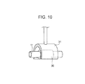
- FIG. 10 is a perspective view illustrating a heater for heating the shape-memory alloy connection pipe of FIG. 8 .
- connection pipes 30 each made of a shape-memory alloy having characteristics that, when it is heated and reaches a certain temperature, the shape thereof is restored to its original shape are connected to both ends of the spool piece 28, and the end of the cut existing measurement pipe 11 is inserted into the end of each connection pipe 30 for connection (step S3a).
- the shape-memory alloy connection pipe 30 has a driver 17 and a liner 18 fitted to the inner circumferential surface of the driver 17.
- the shape-memory alloy connection pipe 30 is cooled with coolant such as liquid nitrogen or dry ice to a temperature range where the driver 17 is deformable.
- a rod member 19 having a tapered lower part is inserted into the driver 17 while a predetermined load is applied to expand the inner diameter of the driver 17 to a size capable of accommodating the liner 18 having a plurality of claw portions 18a in the inner circumference thereof (refer to FIG. 9C ).
- the inner diameter of the liner 18 is set to a size allowing easy insertion of the measurement, pipe 11.
- the liner 18 is inserted into the expanded driver 17.
- step S3b a heater 31 for uniformly heating the outer surface of the shape-memory alloy connection pipe 30 is installed in the reactor as illustrated in FIG. 9 upon completion of the insertion of the end of the broken measurement pipe 11, and the heater 31 is used to heat the driver 17 until the size of the driver 17 is restored to the size before the expansion.
- the heater 31 is formed into a shape obtained by cutting a pipe in its axial direction and can thus uniformly heat the shape-memory alloy 30 to be heated by utilizing the radiation and convection of heat from a heating source.
- This heater 31 is easy to remove, so that it can be used in a narrow portion in the reactor.
- step S3c The driver 17 heated by the heater 31 is contracted to compress the liner 18 in the driver 17.
- the claw portions 18a formed in the inner circumference of the liner 18 bite into the measurement pipe 11, thereby increasing the connection strength with the measurement pipe 11 and enhancing sealing property (step S3c).
- this method can cope with a breakage event occurring in a narrow portion of the lower part where the measurement pipe 11 is horizontally arranged in the water, improving workability of the connection work for connecting the ends of the cut portion, which enables a reduction in the work periods for repair.
- the samples cut by the cutting devices 24 and 24b are collected in a state where they are retained by the gripping tools 26 and 26b, allowing the causes of the breakage to be investigated from the breakage surface of each sample.
- the ends of the cut measurement pipe 11 are connected by the shape-memory alloys 30 with the spool piece 28 interposed between the shape-memory alloys 30.
- the ends of the cut measurement pipe 11 may be connected directly by one shape-memory alloy 30 without intervention of the spool piece 28.
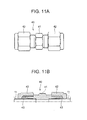
- FIGS. 11A and 11B are a front view and a partially cross-sectional view illustrating the connection pipe of a biting joint used in a second embodiment.
- connection pipe used in step S3 of FIG. 1 is not the shape-memory alloy (SMA) connection portion 30 as described in the first embodiment, but a biting joint 40 as illustrated in FIGS. 10A and 10B .
- Components other than the connection pipe are the same as those of the first embodiment.
- the biting joint 40 is constituted by three parts: a joint body 41, a union nut 42; and a sleeve 43.
- the other end of the broken measurement pipe 11 is inserted into the other insertion port of the biting joint 40 followed by tightening the union nut 42, thereby establishing connection of the broken measurement pipe 11.
- the tightening of the union nut 42 can be achieved by using a small remote ratchet wrench, allowing the union nut 42 to be tightened in a narrow portion in the reactor.
- biting joint 40 as the connection pipe allows a robust repair method having a short preparation time and a short repair time to be provided as in the case of the first embodiment.
- the ends of the broken measurement pipe 11 may be connected by using the biting joints 40 respectively with the spool piece 28 interposed between the biting joints 40.
- FIG. 12 is an enlarged cross-sectional view illustrating the connection pipe of fillet welding used in a third embodiment.
- one end and the other end of the measurement pipe 11 whose horizontal part has been broken are welded through a joint 45 for connection.
- the joint 45 made of the same material as that of the measurement pipe 11 is introduced inside the reactor using a remote control gripping tool. Subsequently, one end of the broken measurement pipe 11 is inserted into the joint 45 followed by fillet welding in the circumferential direction of the measurement pipe 11 to thereby form a fillet-welded portion 46.
- the other end of the measurement pipe 11 is inserted into the joint 45 followed by the welding to thereby achieve the connection of the measurement pipe 11.
- the welding is performed by means of, e.g., underwater laser welding capable of performing welding of the horizontally extending part of the measurement pipe 11.
- the repair work of the present embodiment requires only bringing down an underwater laser welding machine, allowing the repair work to be performed in a narrow space.
- the ends of the broken measurement pipe 11 are welded with the joints 45 with the spool piece 28 interposed between the joints 45.
Landscapes
- Engineering & Computer Science (AREA)
- Physics & Mathematics (AREA)
- General Engineering & Computer Science (AREA)
- Plasma & Fusion (AREA)
- High Energy & Nuclear Physics (AREA)
- Fluid Mechanics (AREA)
- Mechanical Engineering (AREA)
- Monitoring And Testing Of Nuclear Reactors (AREA)
Applications Claiming Priority (1)
| Application Number | Priority Date | Filing Date | Title |
|---|---|---|---|
| JP2010276188A JP5687481B2 (ja) | 2010-12-10 | 2010-12-10 | ジェットポンプ計測用配管の補修方法 |
Publications (3)
| Publication Number | Publication Date |
|---|---|
| EP2463527A2 true EP2463527A2 (fr) | 2012-06-13 |
| EP2463527A3 EP2463527A3 (fr) | 2014-06-11 |
| EP2463527B1 EP2463527B1 (fr) | 2016-10-26 |
Family
ID=45464237
Family Applications (1)
| Application Number | Title | Priority Date | Filing Date |
|---|---|---|---|
| EP11192764.6A Not-in-force EP2463527B1 (fr) | 2010-12-10 | 2011-12-09 | Procédé de réparation de conduite de mesure de pompe à jet |
Country Status (5)
| Country | Link |
|---|---|
| US (1) | US9312036B2 (fr) |
| EP (1) | EP2463527B1 (fr) |
| JP (1) | JP5687481B2 (fr) |
| ES (1) | ES2610914T3 (fr) |
| TW (1) | TWI470648B (fr) |
Families Citing this family (7)
| Publication number | Priority date | Publication date | Assignee | Title |
|---|---|---|---|---|
| US8565366B2 (en) * | 2007-04-09 | 2013-10-22 | General Electric Company | Methods and apparatuses for operating and repairing nuclear reactors |
| JP2013152106A (ja) * | 2012-01-24 | 2013-08-08 | Toshiba Corp | ジェットポンプ計測用配管の補修方法及びその補修装置 |
| JP5703238B2 (ja) * | 2012-01-27 | 2015-04-15 | 株式会社東芝 | 原子炉内計測用配管保全クランプ装置 |
| US9659676B2 (en) * | 2012-10-18 | 2017-05-23 | Westinghouse Electric Company Llc | Jet pump diffuser stack repair |
| US11047398B2 (en) | 2014-08-05 | 2021-06-29 | Energy Recovery, Inc. | Systems and methods for repairing fluid handling equipment |
| WO2017087106A2 (fr) * | 2015-10-16 | 2017-05-26 | Holtec International | Conteneurs de stockage de déchets nucléaires |
| US10591094B1 (en) * | 2016-06-08 | 2020-03-17 | The United States Of America, As Represented By The Secretary Of The Navy | Replaceable union nut |
Citations (2)
| Publication number | Priority date | Publication date | Assignee | Title |
|---|---|---|---|---|
| JP2004209515A (ja) | 2002-12-27 | 2004-07-29 | Toshiba Corp | ジェットポンプ計測配管の水中レーザ溶接補修方法およびレーザ溶接装置 |
| JP4298527B2 (ja) | 2004-01-26 | 2009-07-22 | 日立Geニュークリア・エナジー株式会社 | ジェットポンプ差圧計測管の補修装置 |
Family Cites Families (13)
| Publication number | Priority date | Publication date | Assignee | Title |
|---|---|---|---|---|
| US2011433A (en) * | 1933-03-25 | 1935-08-13 | Michigan Steel Casting Company | Pipe coupling |
| JPS62153796A (ja) | 1985-12-27 | 1987-07-08 | 株式会社日立製作所 | 水中配管の修理方法 |
| JP2896191B2 (ja) * | 1990-04-27 | 1999-05-31 | 株式会社東芝 | ジェットポンプの補修方法 |
| US5796797A (en) * | 1997-02-14 | 1998-08-18 | General Electric Company | Method for sealing a stub tube in a nuclear reactor |
| US6195892B1 (en) * | 1998-05-29 | 2001-03-06 | Mpr Associates, Inc. | Method for replacing cracked core spray supply piping in a boiling water reactor |
| US6233301B1 (en) * | 1998-09-25 | 2001-05-15 | General Electric Company | Jet pump sensing line T-bolt clamp electrode discharge machining tool |
| US6264203B1 (en) * | 1999-01-29 | 2001-07-24 | Mpr Associates, Inc. | Methods and apparatus for repairing a cracked jet pump riser in a boiling water reactor utilizing a spacer camp |
| JP2002168992A (ja) * | 2000-11-30 | 2002-06-14 | Hitachi Ltd | 原子炉圧力容器内補修方法及び補修装置 |
| US6834092B2 (en) * | 2002-07-15 | 2004-12-21 | General Electric Company | Method of repairing leaking elongate hollow members in boiling water reactors |
| US7092477B2 (en) * | 2002-10-01 | 2006-08-15 | Westinghouse Electric Co Llc | BWR inspection manipulator |
| US7578191B2 (en) * | 2006-12-22 | 2009-08-25 | General Electric Company | Reactor jet pump sensing line frequency measurement |
| US8565366B2 (en) * | 2007-04-09 | 2013-10-22 | General Electric Company | Methods and apparatuses for operating and repairing nuclear reactors |
| JP5688383B2 (ja) * | 2012-01-31 | 2015-03-25 | 日立Geニュークリア・エナジー株式会社 | シュラウドサポートの補修方法及びその補修装置 |
-
2010
- 2010-12-10 JP JP2010276188A patent/JP5687481B2/ja active Active
-
2011
- 2011-12-08 TW TW100145314A patent/TWI470648B/zh not_active IP Right Cessation
- 2011-12-09 US US13/315,887 patent/US9312036B2/en active Active
- 2011-12-09 ES ES11192764.6T patent/ES2610914T3/es active Active
- 2011-12-09 EP EP11192764.6A patent/EP2463527B1/fr not_active Not-in-force
Patent Citations (2)
| Publication number | Priority date | Publication date | Assignee | Title |
|---|---|---|---|---|
| JP2004209515A (ja) | 2002-12-27 | 2004-07-29 | Toshiba Corp | ジェットポンプ計測配管の水中レーザ溶接補修方法およびレーザ溶接装置 |
| JP4298527B2 (ja) | 2004-01-26 | 2009-07-22 | 日立Geニュークリア・エナジー株式会社 | ジェットポンプ差圧計測管の補修装置 |
Also Published As
| Publication number | Publication date |
|---|---|
| US20120144641A1 (en) | 2012-06-14 |
| JP5687481B2 (ja) | 2015-03-18 |
| TWI470648B (zh) | 2015-01-21 |
| TW201241838A (en) | 2012-10-16 |
| ES2610914T3 (es) | 2017-05-04 |
| US9312036B2 (en) | 2016-04-12 |
| JP2012122970A (ja) | 2012-06-28 |
| EP2463527B1 (fr) | 2016-10-26 |
| EP2463527A3 (fr) | 2014-06-11 |
Similar Documents
| Publication | Publication Date | Title |
|---|---|---|
| EP2463527B1 (fr) | Procédé de réparation de conduite de mesure de pompe à jet | |
| EP2346049B1 (fr) | Cuve de réacteur et procédé de montage d'une buse d'une telle cuve de réacteur | |
| JP5288767B2 (ja) | ジェットポンプディフューザ溶接部補修装置 | |
| US6990714B2 (en) | Modular submersible repairing system and repairing method | |
| JP2009075077A (ja) | 原子炉内計測用配管の固定装置およびそれを用いた固定工法 | |
| EP2060839B1 (fr) | Procédé et appareil pour réparer un tuyau de goulotte de pulvérisation au coeur dans un réacteur nucléaire | |
| MX2007012424A (es) | Dispositivo y metodo para reparacion de soldadura de difusor de bomba de chorro. | |
| JP2012127961A (ja) | 圧迫によるライザ管の補修の方法および装置 | |
| CN201105420Y (zh) | 用于炉壳现场拼接的错口矫正夹具 | |
| JP2008256586A (ja) | ジェットポンプのライザ管部作業におけるアクセス装置、アクセス装置の使用方法およびアクセス装置回転補助装置 | |
| JP2008261854A (ja) | 原子炉を運転するまた補修するための方法及び装置 | |
| JPH0643287A (ja) | セグメント状計装管 | |
| KR100873953B1 (ko) | 증기발생기 결함 전열관에 설치된 용접식 관마개의 인출장치 | |
| US10283226B2 (en) | Method of repairing jet pump measuring pipe and repair device therefor | |
| CN109163862A (zh) | 一种管件的试压方法 | |
| KR102703803B1 (ko) | 원자력발전소의 노즐 정비용 가공장치 | |
| JP5376914B2 (ja) | プラント設備の放射線透過試験装置および試験方法 | |
| JP2000214290A (ja) | 炉心スプレイ系配管の交換方法 | |
| JP4393011B2 (ja) | 炉心スプレイ系統機器の取替方法 | |
| JP2731300B2 (ja) | 配管結合用クランプの取扱装置 | |
| JPS62153796A (ja) | 水中配管の修理方法 | |
| Atsushi et al. | The stress corrosion cracking at shroud support Tsuruga unit 1 | |
| JP2000162362A (ja) | ジェットポンプシール装置 |
Legal Events
| Date | Code | Title | Description |
|---|---|---|---|
| PUAI | Public reference made under article 153(3) epc to a published international application that has entered the european phase |
Free format text: ORIGINAL CODE: 0009012 |
|
| 17P | Request for examination filed |
Effective date: 20111209 |
|
| AK | Designated contracting states |
Kind code of ref document: A2 Designated state(s): AL AT BE BG CH CY CZ DE DK EE ES FI FR GB GR HR HU IE IS IT LI LT LU LV MC MK MT NL NO PL PT RO RS SE SI SK SM TR |
|
| AX | Request for extension of the european patent |
Extension state: BA ME |
|
| PUAL | Search report despatched |
Free format text: ORIGINAL CODE: 0009013 |
|
| AK | Designated contracting states |
Kind code of ref document: A3 Designated state(s): AL AT BE BG CH CY CZ DE DK EE ES FI FR GB GR HR HU IE IS IT LI LT LU LV MC MK MT NL NO PL PT RO RS SE SI SK SM TR |
|
| AX | Request for extension of the european patent |
Extension state: BA ME |
|
| RIC1 | Information provided on ipc code assigned before grant |
Ipc: G21C 17/10 20060101ALN20140507BHEP Ipc: G21C 17/017 20060101ALI20140507BHEP Ipc: G21C 19/14 20060101ALI20140507BHEP Ipc: G21C 15/25 20060101ALI20140507BHEP Ipc: F16L 55/16 20060101ALI20140507BHEP Ipc: F04F 5/54 20060101AFI20140507BHEP |
|
| 17Q | First examination report despatched |
Effective date: 20150921 |
|
| GRAP | Despatch of communication of intention to grant a patent |
Free format text: ORIGINAL CODE: EPIDOSNIGR1 |
|
| RIC1 | Information provided on ipc code assigned before grant |
Ipc: F04F 5/54 20060101AFI20160427BHEP Ipc: G21C 19/14 20060101ALI20160427BHEP Ipc: F16L 55/16 20060101ALI20160427BHEP Ipc: G21C 15/25 20060101ALI20160427BHEP Ipc: G21C 17/017 20060101ALI20160427BHEP Ipc: G21C 17/10 20060101ALN20160427BHEP |
|
| INTG | Intention to grant announced |
Effective date: 20160518 |
|
| GRAS | Grant fee paid |
Free format text: ORIGINAL CODE: EPIDOSNIGR3 |
|
| GRAA | (expected) grant |
Free format text: ORIGINAL CODE: 0009210 |
|
| AK | Designated contracting states |
Kind code of ref document: B1 Designated state(s): AL AT BE BG CH CY CZ DE DK EE ES FI FR GB GR HR HU IE IS IT LI LT LU LV MC MK MT NL NO PL PT RO RS SE SI SK SM TR |
|
| REG | Reference to a national code |
Ref country code: GB Ref legal event code: FG4D |
|
| REG | Reference to a national code |
Ref country code: CH Ref legal event code: EP |
|
| REG | Reference to a national code |
Ref country code: FR Ref legal event code: PLFP Year of fee payment: 6 |
|
| REG | Reference to a national code |
Ref country code: AT Ref legal event code: REF Ref document number: 840237 Country of ref document: AT Kind code of ref document: T Effective date: 20161115 |
|
| REG | Reference to a national code |
Ref country code: IE Ref legal event code: FG4D |
|
| REG | Reference to a national code |
Ref country code: DE Ref legal event code: R096 Ref document number: 602011031626 Country of ref document: DE |
|
| REG | Reference to a national code |
Ref country code: LT Ref legal event code: MG4D |
|
| PG25 | Lapsed in a contracting state [announced via postgrant information from national office to epo] |
Ref country code: LV Free format text: LAPSE BECAUSE OF FAILURE TO SUBMIT A TRANSLATION OF THE DESCRIPTION OR TO PAY THE FEE WITHIN THE PRESCRIBED TIME-LIMIT Effective date: 20161026 |
|
| REG | Reference to a national code |
Ref country code: NL Ref legal event code: MP Effective date: 20161026 |
|
| REG | Reference to a national code |
Ref country code: AT Ref legal event code: MK05 Ref document number: 840237 Country of ref document: AT Kind code of ref document: T Effective date: 20161026 |
|
| PG25 | Lapsed in a contracting state [announced via postgrant information from national office to epo] |
Ref country code: SE Free format text: LAPSE BECAUSE OF FAILURE TO SUBMIT A TRANSLATION OF THE DESCRIPTION OR TO PAY THE FEE WITHIN THE PRESCRIBED TIME-LIMIT Effective date: 20161026 Ref country code: GR Free format text: LAPSE BECAUSE OF FAILURE TO SUBMIT A TRANSLATION OF THE DESCRIPTION OR TO PAY THE FEE WITHIN THE PRESCRIBED TIME-LIMIT Effective date: 20170127 Ref country code: LT Free format text: LAPSE BECAUSE OF FAILURE TO SUBMIT A TRANSLATION OF THE DESCRIPTION OR TO PAY THE FEE WITHIN THE PRESCRIBED TIME-LIMIT Effective date: 20161026 Ref country code: NO Free format text: LAPSE BECAUSE OF FAILURE TO SUBMIT A TRANSLATION OF THE DESCRIPTION OR TO PAY THE FEE WITHIN THE PRESCRIBED TIME-LIMIT Effective date: 20170126 |
|
| REG | Reference to a national code |
Ref country code: ES Ref legal event code: FG2A Ref document number: 2610914 Country of ref document: ES Kind code of ref document: T3 Effective date: 20170504 |
|
| PG25 | Lapsed in a contracting state [announced via postgrant information from national office to epo] |
Ref country code: HR Free format text: LAPSE BECAUSE OF FAILURE TO SUBMIT A TRANSLATION OF THE DESCRIPTION OR TO PAY THE FEE WITHIN THE PRESCRIBED TIME-LIMIT Effective date: 20161026 Ref country code: BE Free format text: LAPSE BECAUSE OF FAILURE TO SUBMIT A TRANSLATION OF THE DESCRIPTION OR TO PAY THE FEE WITHIN THE PRESCRIBED TIME-LIMIT Effective date: 20161026 Ref country code: RS Free format text: LAPSE BECAUSE OF FAILURE TO SUBMIT A TRANSLATION OF THE DESCRIPTION OR TO PAY THE FEE WITHIN THE PRESCRIBED TIME-LIMIT Effective date: 20161026 Ref country code: AT Free format text: LAPSE BECAUSE OF FAILURE TO SUBMIT A TRANSLATION OF THE DESCRIPTION OR TO PAY THE FEE WITHIN THE PRESCRIBED TIME-LIMIT Effective date: 20161026 Ref country code: PT Free format text: LAPSE BECAUSE OF FAILURE TO SUBMIT A TRANSLATION OF THE DESCRIPTION OR TO PAY THE FEE WITHIN THE PRESCRIBED TIME-LIMIT Effective date: 20170227 Ref country code: PL Free format text: LAPSE BECAUSE OF FAILURE TO SUBMIT A TRANSLATION OF THE DESCRIPTION OR TO PAY THE FEE WITHIN THE PRESCRIBED TIME-LIMIT Effective date: 20161026 Ref country code: FI Free format text: LAPSE BECAUSE OF FAILURE TO SUBMIT A TRANSLATION OF THE DESCRIPTION OR TO PAY THE FEE WITHIN THE PRESCRIBED TIME-LIMIT Effective date: 20161026 Ref country code: NL Free format text: LAPSE BECAUSE OF FAILURE TO SUBMIT A TRANSLATION OF THE DESCRIPTION OR TO PAY THE FEE WITHIN THE PRESCRIBED TIME-LIMIT Effective date: 20161026 Ref country code: IS Free format text: LAPSE BECAUSE OF FAILURE TO SUBMIT A TRANSLATION OF THE DESCRIPTION OR TO PAY THE FEE WITHIN THE PRESCRIBED TIME-LIMIT Effective date: 20170226 |
|
| REG | Reference to a national code |
Ref country code: DE Ref legal event code: R119 Ref document number: 602011031626 Country of ref document: DE |
|
| PG25 | Lapsed in a contracting state [announced via postgrant information from national office to epo] |
Ref country code: RO Free format text: LAPSE BECAUSE OF FAILURE TO SUBMIT A TRANSLATION OF THE DESCRIPTION OR TO PAY THE FEE WITHIN THE PRESCRIBED TIME-LIMIT Effective date: 20161026 Ref country code: CZ Free format text: LAPSE BECAUSE OF FAILURE TO SUBMIT A TRANSLATION OF THE DESCRIPTION OR TO PAY THE FEE WITHIN THE PRESCRIBED TIME-LIMIT Effective date: 20161026 Ref country code: EE Free format text: LAPSE BECAUSE OF FAILURE TO SUBMIT A TRANSLATION OF THE DESCRIPTION OR TO PAY THE FEE WITHIN THE PRESCRIBED TIME-LIMIT Effective date: 20161026 Ref country code: SK Free format text: LAPSE BECAUSE OF FAILURE TO SUBMIT A TRANSLATION OF THE DESCRIPTION OR TO PAY THE FEE WITHIN THE PRESCRIBED TIME-LIMIT Effective date: 20161026 Ref country code: DK Free format text: LAPSE BECAUSE OF FAILURE TO SUBMIT A TRANSLATION OF THE DESCRIPTION OR TO PAY THE FEE WITHIN THE PRESCRIBED TIME-LIMIT Effective date: 20161026 |
|
| REG | Reference to a national code |
Ref country code: CH Ref legal event code: PL |
|
| PG25 | Lapsed in a contracting state [announced via postgrant information from national office to epo] |
Ref country code: SM Free format text: LAPSE BECAUSE OF FAILURE TO SUBMIT A TRANSLATION OF THE DESCRIPTION OR TO PAY THE FEE WITHIN THE PRESCRIBED TIME-LIMIT Effective date: 20161026 Ref country code: IT Free format text: LAPSE BECAUSE OF FAILURE TO SUBMIT A TRANSLATION OF THE DESCRIPTION OR TO PAY THE FEE WITHIN THE PRESCRIBED TIME-LIMIT Effective date: 20161026 Ref country code: BG Free format text: LAPSE BECAUSE OF FAILURE TO SUBMIT A TRANSLATION OF THE DESCRIPTION OR TO PAY THE FEE WITHIN THE PRESCRIBED TIME-LIMIT Effective date: 20170126 |
|
| PLBE | No opposition filed within time limit |
Free format text: ORIGINAL CODE: 0009261 |
|
| STAA | Information on the status of an ep patent application or granted ep patent |
Free format text: STATUS: NO OPPOSITION FILED WITHIN TIME LIMIT |
|
| GBPC | Gb: european patent ceased through non-payment of renewal fee |
Effective date: 20170126 |
|
| PG25 | Lapsed in a contracting state [announced via postgrant information from national office to epo] |
Ref country code: MC Free format text: LAPSE BECAUSE OF FAILURE TO SUBMIT A TRANSLATION OF THE DESCRIPTION OR TO PAY THE FEE WITHIN THE PRESCRIBED TIME-LIMIT Effective date: 20161026 |
|
| 26N | No opposition filed |
Effective date: 20170727 |
|
| REG | Reference to a national code |
Ref country code: IE Ref legal event code: MM4A |
|
| PG25 | Lapsed in a contracting state [announced via postgrant information from national office to epo] |
Ref country code: LU Free format text: LAPSE BECAUSE OF NON-PAYMENT OF DUE FEES Effective date: 20161209 Ref country code: LI Free format text: LAPSE BECAUSE OF NON-PAYMENT OF DUE FEES Effective date: 20161231 Ref country code: CH Free format text: LAPSE BECAUSE OF NON-PAYMENT OF DUE FEES Effective date: 20161231 |
|
| REG | Reference to a national code |
Ref country code: FR Ref legal event code: PLFP Year of fee payment: 7 |
|
| PG25 | Lapsed in a contracting state [announced via postgrant information from national office to epo] |
Ref country code: SI Free format text: LAPSE BECAUSE OF FAILURE TO SUBMIT A TRANSLATION OF THE DESCRIPTION OR TO PAY THE FEE WITHIN THE PRESCRIBED TIME-LIMIT Effective date: 20161026 Ref country code: DE Free format text: LAPSE BECAUSE OF NON-PAYMENT OF DUE FEES Effective date: 20170701 Ref country code: IE Free format text: LAPSE BECAUSE OF NON-PAYMENT OF DUE FEES Effective date: 20161209 Ref country code: GB Free format text: LAPSE BECAUSE OF NON-PAYMENT OF DUE FEES Effective date: 20170126 |
|
| PG25 | Lapsed in a contracting state [announced via postgrant information from national office to epo] |
Ref country code: HU Free format text: LAPSE BECAUSE OF FAILURE TO SUBMIT A TRANSLATION OF THE DESCRIPTION OR TO PAY THE FEE WITHIN THE PRESCRIBED TIME-LIMIT; INVALID AB INITIO Effective date: 20111209 Ref country code: CY Free format text: LAPSE BECAUSE OF FAILURE TO SUBMIT A TRANSLATION OF THE DESCRIPTION OR TO PAY THE FEE WITHIN THE PRESCRIBED TIME-LIMIT Effective date: 20161026 |
|
| PG25 | Lapsed in a contracting state [announced via postgrant information from national office to epo] |
Ref country code: TR Free format text: LAPSE BECAUSE OF FAILURE TO SUBMIT A TRANSLATION OF THE DESCRIPTION OR TO PAY THE FEE WITHIN THE PRESCRIBED TIME-LIMIT Effective date: 20161026 Ref country code: MK Free format text: LAPSE BECAUSE OF FAILURE TO SUBMIT A TRANSLATION OF THE DESCRIPTION OR TO PAY THE FEE WITHIN THE PRESCRIBED TIME-LIMIT Effective date: 20161026 |
|
| PG25 | Lapsed in a contracting state [announced via postgrant information from national office to epo] |
Ref country code: MT Free format text: LAPSE BECAUSE OF NON-PAYMENT OF DUE FEES Effective date: 20161209 |
|
| PG25 | Lapsed in a contracting state [announced via postgrant information from national office to epo] |
Ref country code: AL Free format text: LAPSE BECAUSE OF FAILURE TO SUBMIT A TRANSLATION OF THE DESCRIPTION OR TO PAY THE FEE WITHIN THE PRESCRIBED TIME-LIMIT Effective date: 20161026 |
|
| PGFP | Annual fee paid to national office [announced via postgrant information from national office to epo] |
Ref country code: FR Payment date: 20230929 Year of fee payment: 13 |
|
| PGFP | Annual fee paid to national office [announced via postgrant information from national office to epo] |
Ref country code: ES Payment date: 20240118 Year of fee payment: 13 |
|
| PG25 | Lapsed in a contracting state [announced via postgrant information from national office to epo] |
Ref country code: FR Free format text: LAPSE BECAUSE OF NON-PAYMENT OF DUE FEES Effective date: 20241231 |
|
| REG | Reference to a national code |
Ref country code: ES Ref legal event code: FD2A Effective date: 20260128 |
|
| PG25 | Lapsed in a contracting state [announced via postgrant information from national office to epo] |
Ref country code: ES Free format text: LAPSE BECAUSE OF NON-PAYMENT OF DUE FEES Effective date: 20241210 |