EP2463662A2 - Station einer Rohrpostanlage - Google Patents
Station einer Rohrpostanlage Download PDFInfo
- Publication number
- EP2463662A2 EP2463662A2 EP20110192399 EP11192399A EP2463662A2 EP 2463662 A2 EP2463662 A2 EP 2463662A2 EP 20110192399 EP20110192399 EP 20110192399 EP 11192399 A EP11192399 A EP 11192399A EP 2463662 A2 EP2463662 A2 EP 2463662A2
- Authority
- EP
- European Patent Office
- Prior art keywords
- station
- tube
- pneumatic
- tubes
- receiving
- Prior art date
- Legal status (The legal status is an assumption and is not a legal conclusion. Google has not performed a legal analysis and makes no representation as to the accuracy of the status listed.)
- Granted
Links
Images
Classifications
-
- G—PHYSICS
- G01—MEASURING; TESTING
- G01N—INVESTIGATING OR ANALYSING MATERIALS BY DETERMINING THEIR CHEMICAL OR PHYSICAL PROPERTIES
- G01N35/00—Automatic analysis not limited to methods or materials provided for in any single one of groups G01N1/00 - G01N33/00; Handling materials therefor
- G01N35/02—Automatic analysis not limited to methods or materials provided for in any single one of groups G01N1/00 - G01N33/00; Handling materials therefor using a plurality of sample containers moved by a conveyor system past one or more treatment or analysis stations
- G01N35/04—Details of the conveyor system
-
- B—PERFORMING OPERATIONS; TRANSPORTING
- B65—CONVEYING; PACKING; STORING; HANDLING THIN OR FILAMENTARY MATERIAL
- B65G—TRANSPORT OR STORAGE DEVICES, e.g. CONVEYORS FOR LOADING OR TIPPING, SHOP CONVEYOR SYSTEMS OR PNEUMATIC TUBE CONVEYORS
- B65G51/00—Conveying articles through pipes or tubes by fluid flow or pressure; Conveying articles over a flat surface, e.g. the base of a trough, by jets located in the surface
- B65G51/04—Conveying the articles in carriers having a cross-section approximating that of the pipe or tube; Tube mail systems
- B65G51/26—Stations
- B65G51/32—Stations for despatch, delivery, and transit
-
- G—PHYSICS
- G01—MEASURING; TESTING
- G01N—INVESTIGATING OR ANALYSING MATERIALS BY DETERMINING THEIR CHEMICAL OR PHYSICAL PROPERTIES
- G01N35/00—Automatic analysis not limited to methods or materials provided for in any single one of groups G01N1/00 - G01N33/00; Handling materials therefor
- G01N35/00584—Control arrangements for automatic analysers
- G01N35/00722—Communications; Identification
- G01N35/00732—Identification of carriers, materials or components in automatic analysers
-
- G—PHYSICS
- G01—MEASURING; TESTING
- G01N—INVESTIGATING OR ANALYSING MATERIALS BY DETERMINING THEIR CHEMICAL OR PHYSICAL PROPERTIES
- G01N35/00—Automatic analysis not limited to methods or materials provided for in any single one of groups G01N1/00 - G01N33/00; Handling materials therefor
- G01N35/00584—Control arrangements for automatic analysers
- G01N35/00722—Communications; Identification
- G01N35/00732—Identification of carriers, materials or components in automatic analysers
- G01N2035/00742—Type of codes
- G01N2035/00772—Type of codes mechanical or optical code other than bar code
-
- G—PHYSICS
- G01—MEASURING; TESTING
- G01N—INVESTIGATING OR ANALYSING MATERIALS BY DETERMINING THEIR CHEMICAL OR PHYSICAL PROPERTIES
- G01N35/00—Automatic analysis not limited to methods or materials provided for in any single one of groups G01N1/00 - G01N33/00; Handling materials therefor
- G01N35/02—Automatic analysis not limited to methods or materials provided for in any single one of groups G01N1/00 - G01N33/00; Handling materials therefor using a plurality of sample containers moved by a conveyor system past one or more treatment or analysis stations
- G01N35/04—Details of the conveyor system
- G01N2035/046—General conveyor features
- G01N2035/0465—Loading or unloading the conveyor
-
- G—PHYSICS
- G01—MEASURING; TESTING
- G01N—INVESTIGATING OR ANALYSING MATERIALS BY DETERMINING THEIR CHEMICAL OR PHYSICAL PROPERTIES
- G01N35/00—Automatic analysis not limited to methods or materials provided for in any single one of groups G01N1/00 - G01N33/00; Handling materials therefor
- G01N35/02—Automatic analysis not limited to methods or materials provided for in any single one of groups G01N1/00 - G01N33/00; Handling materials therefor using a plurality of sample containers moved by a conveyor system past one or more treatment or analysis stations
- G01N35/04—Details of the conveyor system
- G01N2035/0474—Details of actuating means for conveyors or pipettes
- G01N2035/0479—Details of actuating means for conveyors or pipettes hydraulic or pneumatic
- G01N2035/0481—Pneumatic tube conveyors; Tube mails; "Rohrpost"
Definitions
- the present invention relates to a station of a pneumatic tube system for transporting pneumatic tubes, the contents of portions, preferably in sample tubes, supplied with automatic Ausladefunktionsaku for the contents of the pneumatic tubes and its transfer to an analysis station or other processing, wherein at least two tubes in the Station lead.
- Pneumatic tube systems are always used where material is to be transported in small portions, such as in banks, pharmacies and in hospitals. Such systems consist of transmitting and receiving stations and a network of pipes. Preferably, the material to be transported is transported in pneumatic tube sleeves.
- the small units to be transported in hospitals and laboratories sample tubes with blood or biological material) are often in the pneumatic tubes in their own applications, such as in the description of WO 2009/068574 A set out, transported.
- a pneumatic tube station of the type mentioned is known, inter alia, from the just cited WO 2009/068574 A , In this case, pneumatic tubes are automatically unloaded and the content, sample tube either passed on to an analysis unit or, if the content of the shipment can not be processed automatically in this analysis unit, in a pneumatic tube sleeve to a corresponding laboratory rubverschreib. The empty tubes are returned in the same tube as they entered the station.
- the known station with a tube in which the pneumatic tubes are both returned and emptied sent back too little capacity. If e.g. If a tube post sleeve is sent from the pathology, then all other stations (such as the emergency room) must wait until the sleeve arrives at the station from the pathology in the laboratory, is emptied, and sent back empty. Only then, the tube is free, and the sleeve from the emergency room can be sent.
- Object of the present invention is therefore to propose a station of the type mentioned, which avoids the aforementioned disadvantages and increases the transmission frequencies.
- a station of the type mentioned above in that one tube is a receiving tube and the other tube is a transmitter ear, wherein in the station the receiving tube, the transmitter ear and the Ausladefunktionsech each have a receiving position, a transmission position and an unloading position are assigned of which at least two are different, that in the station a carriage movable at least between these different positions is mounted and that the station is preceded by a separator.
- the Ausladefunktionsaku is followed by a wegschwenkbare control unit. After opening and subsequent emptying of the pneumatic tubes, the pneumatic tube should be empty.
- the control unit which - in order to avoid collisions - can be swung during unloading, this - after it was swung back after unloading - check so that the next step required in each case can be arranged and is not mistakenly a half-full pneumatic tube post subsequently sent back.
- the station has an identification device or such a station is connected upstream.
- An automatic recognition of the target address of a sleeve and an identification advantageous manner by RFID transponders, as well as the detection of possible false shipments and the subsequent control save time-consuming random walks of the sleeves or incorrect processing of their contents.
- the station has an opening for discharging pneumatic mail tubes, which is assigned a discharge position, and if the carriage is movably mounted between the discharge position, the receiving position, the sending position and the unloading position.
- Sleeves that can not be emptied automatically are removed from the system.
- pods whose destination is unclear can be ejected. This elimination of false mail helps to correct errors early. Due to the three positions, an incorrect shipment does not have to be returned like the empty shipments, but can be fed back into the system at a separate location.
- the station upstream of the station has at least one conveyor element which is spring-loaded in the direction of the center of the pipe.
- conveying elements come conveyor rollers or Conveyor belts in question. By such conveying elements, the pneumatic tube sleeves are gently and slowly moved, and subsequently prevents multiple pods get into the station at the same time.
- connection to an analysis station or a further processing can be done from above or below.
- a connection from below is in the already mentioned WO2009 / 068574A described for sample tubes. With a connection from above one can let out the content simply, as in the description introduction of the AT402396 B is mentioned, and transport on a slide with a laterally located conveyor belt with protruding strips for separation of sample tubes, as for example from the JP2000019182 A is known.
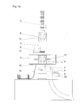
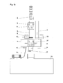
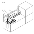
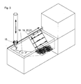
- FIG. 1a A preferred embodiment of a station according to the invention with connection to a pneumatic tube system is shown schematically in FIG Fig. 1a shown; Fig. 1 b shows a variant too Fig. 1a ; Fig. 2 schematically shows a possible connection to an analysis station with feed from below; Fig. 3 schematically shows a possible connection to an analysis station with supply from above.
- Fig. 1a enter pneumatic tube sleeves 2 in a multi-tube transport system, as desired in large hospitals, in a receiving tube 3 of a station 1.
- This station 1 is suitably designed so that they different sleeve lengths and Can handle sleeve shapes.
- the front in the direction of travel pneumatic tube sleeve 2 first passes into the singler 6, where it can be held or moved by the converging in the direction of travel conveyor belts 11 of a belt drive. She is now in waiting position.
- the conveyor belts 11 move a pneumatic tube sleeve 2 slowly in the direction of station 1, so that it encounters a slide 12, which is initially in the closed position.
- the pneumatic tube sleeve 2 is then positioned exactly in this position for receiving in the station 1. If the station 1 is ready for receiving a pneumatic tube 2, the pneumatic tube is released by movement of the slider 12 normal to the direction of travel, and the pneumatic tube 2 enters the station 1.
- the slider 12 can now be closed again, and then leaves the singler 6 a slide further tube post sleeve onto the slide 12.
- an identification unit 9 automatically detects the pneumatic tube 2 and identifies it preferably with the aid of an RFID transponder. In this case, an incorrect transmission can be detected, the transmission time can be determined, and the destination address can be determined. Airtime and other data can be evaluated afterwards, be it for statistical purposes, be it for optimization purposes or similar.
- the identification unit may be integrated in the station 1; Preferably, however, it is arranged immediately in front of the slider 12, where the pneumatic tube sleeve 2 is in the rest position for a short time.
- the conveyor belts 11 ' which are arranged as in the singler 6, and the same way as in the singler 6 initially hold the pneumatic tube 2 to move them later up and down.
- the carriage 5 itself is automatically displaced linearly between at least three positions, namely between a transmission position, a reception position and an ejection position.
- the reception position is in the middle, the ejection position on the left and the transmission position on the right.
- the positions can be chosen as best suited to the space available.
- Actuators, data acquisition, evaluation and control units that initiate the movements of individual parts such as the belt drive or the singler 6 are in the schematic representations in the FIGS. 1a . 1 b . 2 and 3 not shown.
- the Ausladefunktionstician could eg in Fig. 1b as well as against the transmitter ear 4 'be arranged, or it could be provided a fourth position of the carriage for the Ausladefunktionsaku.
- This unloading function unit is a main unit and is off AT 402396 B respectively.
- AT 11306 U1 known, where in each case an automatic sleeve with associated opening mechanism is disclosed.
- a wegschwenkbare control unit 8 which is the Ausladefunktionsussi 7 downstream, checks whether the pneumatic tube 2 is completely emptied.
- the empty sleeve is brought back with the help of the conveyor belts 11 'again completely in the station 1 and the carriage 5 is linearly moved to the send position, so that the pneumatic tube sleeve 2 can be introduced into the transmitter ear 4.
- the return transport is independent of the receiving tube 3.
- This transmitter ear 4 saves waiting times when sending more sleeves to the station.
- This transmitter ear 4 has a further slider 13 installed, which releases the pneumatic tube sleeve 2 for the return transport according to the logically recorded and derived therefrom options.
- Fig. 1 a leads the transmitter ear 4 downwards.
- the respective position of transmitter ear 4 and receiving tube 3 is arbitrary. So could eg in Fig. 1a the position of the Ausladefunktionsaku 7 with the position of the transmitter ear 4 to be reversed, so that in this case the sending position and receiving position of the carriage 6 would be identical and the Ausladeposition of the carriage would be different.
- Fig. 1b differs from Fig. 1a in that a transmitter tube 4 'leading upwards is provided (instead of the transmitter tube 4 leading downwards).
- sending position and receiving position of the carriage 6 are inevitably different.
- it would be conceivable to provide the tube 10 below the transmitter tube 4 ' so that in this case the transmission position of the carriage and the ejection position of the carriage would be identical (as well as the reception position and the unloading position).
- the carriage 5 transfers this pneumatic tube 2 to the opening 10, where the conveyor belts 11 'eject the pneumatic tube 2 on a free slide.
- a free slide 14 may also be provided a basket into which the pneumatic tube sleeves 2 fall.
- Fig. 2 shows the transfer of the sample tubes to the analysis station 22 with supply from below.
- inserts 15 which are removed from a laboratory robot 16 from the open pneumatic tube sleeve 2 and parked.
- the sample tubes are automatically removed individually from the insert 15 and fed to a conveyor belt for sample tube 17.
- Fig. 3 shows a connection to the analysis station 22 with supply from above. This corresponds to the Fig. 1a and 1 b.
- the test tubes fall after opening the pneumatic tube 2 by gravity on a chute 18 and are collected at the lower end of the chute 18.
- a lateral conveyor belt 19 is provided with strips 20 integrally formed normal to the surface of the lateral conveyor belt 19. The strips 20 receive individual sample tubes and lift them up to a linear conveyor belt 21. This transports the tubes to the analysis station 22.
- a station and its connection in the embodiment just described solves the problem of high transmission rates, especially in hospitals at peak times.
Landscapes
- Physics & Mathematics (AREA)
- Health & Medical Sciences (AREA)
- Life Sciences & Earth Sciences (AREA)
- Chemical & Material Sciences (AREA)
- Analytical Chemistry (AREA)
- Biochemistry (AREA)
- General Health & Medical Sciences (AREA)
- General Physics & Mathematics (AREA)
- Immunology (AREA)
- Pathology (AREA)
- Engineering & Computer Science (AREA)
- Fluid Mechanics (AREA)
- Mechanical Engineering (AREA)
- Automatic Analysis And Handling Materials Therefor (AREA)
Abstract
Description
- Die vorliegende Erfindung betrifft eine Station einer Rohrpostanlage zur Beförderung von Rohrposthülsen, deren Inhalt portionsweise, vorzugsweise in Proberöhrchen, geliefert wird, mit automatischer Ausladefunktionseinheit für den Inhalt der Rohrposthülsen und dessen Übergabe zu einer Analysestation beziehungsweise zu einer anderen Weiterverarbeitung, wobei mindestens zwei Rohre in die Station münden.
- Rohrpostanlagen werden immer dort eingesetzt, wo Material in kleinen Portionen transportiert werden soll, wie zum Beispiel in Banken, Apotheken und in Spitälern. Solche Anlagen bestehen aus Sende- und Empfangsstationen sowie einem Netzwerk an Rohren. Vorzugsweise wird das zu transportierende Material in Rohrposthülsen transportiert. Die kleinen zu transportierenden Einheiten (in Spitälern und Laboratorien Proberöhrchen mit Blut oder biologischem Material) werden dabei oft in den Rohrposthülsen in eigenen Einsätzen, wie z.B. in der Beschreibung der
WO 2009/068574 A dargelegt, transportiert. - Eine Rohrpoststation der eingangs genannten Art ist unter anderem bekannt aus der eben zitierten
WO 2009/068574 A . Dabei werden Rohrposthülsen automatisch entladen und der Inhalt, Proberöhrchen entweder an eine Analyseeinheit weitergegeben oder, wenn der Inhalt der Sendung nicht in dieser Analyseeinheit automatisch verarbeitet werden kann, in einer Rohrposthülse zu einem entsprechenden Labor weiterverschickt. Die leeren Hülsen werden im selben Rohr zurückgeschickt, in dem sie in die Station gelangt sind. - In modernen Krankenhausanlagen werden immer häufiger zentrale Labors installiert, um Kosten, Ressourcen und Zeit zu sparen. Von mehreren Stellen eines Krankenhauses (Notaufnahme, Operationssaal, Pathologie etc.) werden Blutproben, Gewebeproben und sonstige zu analysierende Proben in ein zentrales Labor gesendet, wo sie dann analysiert werden. Für Transportzwecke müssen daher solche Krankenhaus-Transportanlagen groß dimensioniert werden, d.h. es kommen viele Stationen und sehr viele Rohrposthülsen zum Einsatz. Somit erlangen Lösungen, die eine rasche Abarbeitung ermöglichen, und die damit verbundene Logistik immer mehr Bedeutung.
- Bei großen Sendefrequenzen weist die bekannte Station mit einem Rohr, in dem die Rohrposthülsen sowohl ankommen als auch geleert wieder zurückgeschickt werden, zu wenig Kapazität auf. Wenn z.B. aus der Pathologie eine Rohrposthülse abgeschickt wird, dann müssen alle anderen Stationen (also z.B. die Notaufnahme) warten, bis die Hülse aus der Pathologie bei der Station im Labor ankommt, entleert wird und leer wieder zurückgeschickt wird. Erst dann ist das Rohr frei, und die Hülse aus der Notaufnahme kann abgesandt werden.
- Aufgabe der vorliegenden Erfindung ist es daher, eine Station der eingangs genannten Art vorzuschlagen, die die vorgenannten Nachteile vermeidet und die Sendefrequenzen erhöht.
- Gelöst wird diese Aufgabe bei einer Station der eingangs genannten Art dadurch, dass das eine Rohr ein Empfangsrohr und das andere Rohr ein Senderohr ist, wobei in der Station dem Empfangsrohr, dem Senderohr und der Ausladefunktionseinheit jeweils eine Empfangsposition, eine Sendeposition und eine Ausladeposition zugeordnet sind, von denen zumindest zwei verschieden sind, dass in der Station ein zumindest zwischen diesen verschiedenen Positionen bewegbarer Schlitten gelagert ist und dass der Station ein Vereinzeler vorgelagert ist.
- Durch diese Maßnahmen wird eine Anbindung einer Station an ein Mehrhülsentransportsystem sichergestellt. Bei solch einem Mehrhülsentransportsystem können mehrere Hülsen nahezu zeitgleich abgesandt werden. Sie liegen dann nach der Ankunft vor der Station (genauer vor dem Vereinzeler) unmittelbar hintereinander. Durch den Vereinzeler wird erreicht, dass stets nur eine Rohrposthülse in die Station gelangt, wo sie automatisch entladen wird und danach (also leer) durch den bewegbaren Schlitten an das Senderohr übergeben wird. Da die leere Hülse in einem eigenen Rohr zurücktransportiert wird, stört es nicht, dass bereits weitere Hülsen im Empfangsrohr "warten".
- Der dazu erforderliche technische Aufwand ist relativ gering, es muss nur die für die Station erforderliche Technik (wie z.B. ein Riementrieb) auf einem bewegbaren Schlitten montiert werden.
- Vorteilhaft ist es dabei, wenn der Ausladefunktionseinheit eine wegschwenkbare Kontrolleinheit nachgeschaltet ist. Nach dem Öffnen und dem darauf folgenden Entleeren der Rohrposthülsen sollte die Rohrposthülse leer sein. Die Kontrolleinheit, die - um Kollisionen zu vermeiden - beim Ausladen weggeschwenkt werden kann, kann dies - nachdem sie nach dem Ausladen zurückgeschwenkt wurde - überprüfen, sodass der jeweils erforderliche nächste Schritt veranlasst werden kann und nicht irrtümlich eine halbvolle Rohrposthülse in weiterer Folge zurückgeschickt wird.
- Weiters ist günstiger Weise vorgesehen, dass die Station eine Identifizierungseinrichtung besitzt beziehungsweise eine solche der Station vorgeschaltet ist. Ein automatisches Erkennen der Zieladresse einer Hülse und eine Identifikation vorteilhafter Weise durch RFID-Transponder sowie das Erkennen eventueller Falschsendungen und die darauf folgende Steuerung ersparen zeitraubende Irrfahrten der Hülsen bzw. falsche Verarbeitungen deren Inhalts.
- Als Vorteil erweist sich, wenn die Station eine Öffnung zum Ausschleusen von Rohrposthülsen besitzt, der eine Ausschleusposition zugeordnet ist, und wenn der Schlitten zwischen der Ausschleuseposition, der Empfangsposition, der Sendeposition und der Ausladeposition bewegbar gelagert ist. Damit können z.B. Hülsen, die sich nicht automatisch entleeren lassen, aus dem System ausgeschleust werden. Auch können Hülsen, deren Zielort unklar ist, ausgeschleust werden. Dieses Ausscheiden von Falschsendungen hilft, Fehler frühzeitig zu korrigieren. Durch die drei Positionen muss eine Falschsendung nicht zurückgesendet werden wie die leeren Sendungen, sondern kann an einer separaten Stelle wieder richtig ins System eingespeist werden.
- Positiv wirkt sich aus, wenn der der Station vorgeschaltete Vereinzeler mindestens ein Förderelement besitzt, das in Richtung Rohrmitte federbelastet ist. Als Förderelemente kommen Förderrollen oder Förderbänder in Frage. Durch solche Förderelemente werden die Rohrposthülsen sanft und langsam bewegt, und in weiterer Folge wird verhindert, dass mehrere Hülsen zugleich in die Station gelangen.
- Als günstig erweist sich, wenn sich zwischen dem Vereinzeler und der Station mindestens ein Schieber zum kurzen Stillstand und anschließender Freigabe einer Rohrposthülse angebracht ist. Dadurch wird eine Ruheposition der Hülse, die zum Identifizieren genutzt werden kann, sowie eine exakte Positionierung zur Übergabe an die Station erreicht. Sobald der Schieber öffnet und eine Hülse in die Station gelangen lässt, wird der Vereinzeler aktiviert und lässt genau eine weitere Hülse auf den mittlerweile wieder geschlossenen Schieber gleiten.
- Die Anbindung an eine Analysestation bzw. eine Weiterverarbeitung kann von oben oder unten erfolgen. Eine Anbindung von unten ist in der schon genannten
WO2009/068574A für Proberöhrchen beschrieben. Bei einer Anbindung von oben kann man den Inhalt einfach herausfallen lassen, wie dies in der Beschreibungseinleitung derAT402396 B JP2000019182 A - Die Erfindung soll anhand der Zeichnungen detaillierter beschrieben werden.
- Eine bevorzugte Ausführungsform einer erfindungsgemäßen Station mit Anbindung an ein Rohrpostsystem ist schematisch in
Fig. 1a dargestellt;Fig. 1 b zeigt eine Variante zuFig. 1a ;Fig. 2 zeigt schematisch eine mögliche Anbindung an eine Analysestation mit Zufuhr von unten;Fig. 3 zeigt schematisch eine mögliche Anbindung an eine Analysestation mit Zufuhr von oben. - Gemäß
Fig. 1a gelangen Rohrposthülsen 2 in einem Mehrhülsentransportsystem, wie in großen Krankenhäusern erwünscht, in ein Empfangsrohr 3 einer Station 1. Diese Station 1 ist zweckmäßiger Weise so ausgelegt, dass sie unterschiedliche Hülsenlängen und Hülsenformen handhaben kann. - Die in Fahrtrichtung vorderste Rohrposthülse 2 gelangt zunächst in den Vereinzeler 6, wo sie durch die in Fahrtrichtung zusammenlaufend ausgerichteten Förderbänder 11 eines Riementriebs gehalten oder bewegt werden kann. Sie befindet sich nun in Warteposition. Die Förderbänder 11 bewegen eine Rohrposthülse 2 langsam in Richtung Station 1, sodass diese auf einen Schieber 12 stößt, der sich vorerst in Geschlossenstellung befindet. Die Rohrposthülse 2 ist in dieser Stellung dann exakt zur Aufnahme in die Station 1 positioniert. Ist die Station 1 zur Aufnahme einer Rohrposthülse 2 bereit, wird durch Bewegung des Schiebers 12 normal zur Fahrtrichtung die Rohrposthülse freigegeben, und die Rohrposthülse 2 gelangt in die Station 1. Der Schieber 12 kann nun wieder geschlossen werden, und danach lässt der Vereinzeler 6 eine weitere Rohrposthülse auf den Schieber 12 gleiten.
- Bevor die in der Station befindliche Rohrposthülse 2 entleert wird, erkennt eine Identifizierungseinheit 9 automatisch die Rohrposthülse 2 und identifiziert sie vorzugsweise mit Hilfe eines RFID-Transponders. Es kann hierbei eine Falschsendung erkannt, die Sendezeit ermittelt sowie die Zieladresse festgestellt werden. Sendezeiten und andere Daten können danach ausgewertet werden, sei es für Statistikzwecke, sei es für Optimierungszwecke oder ähnliches. Die Identifizierungseinheit kann in die Station 1 integriert sein; bevorzugt ist sie aber unmittelbar vor dem Schieber 12 angeordnet, wo sich die Rohrposthülse 2 für kurze Zeit in Ruhestellung befindet.
- In der Station 1 selbst befindet sich ein Schlitten 5, der seinerseits Förderbänder 11', die wie im Vereinzeler 6 angeordnet sind, aufweist und die genau so wie im Vereinzeler 6 vorerst die Rohrposthülse 2 festhalten, um sie später auf und ab zu bewegen.
- Der Schlitten 5 selbst wird automatisch zwischen zumindest drei Positionen linear verschoben, nämlich zwischen einer Sendeposition, einer Empfangsposition und einer Ausschleuseposition. Gemäß
Fig. 1a und1 b befindet sich die Empfangsposition in der Mitte, die Ausschleuseposition links und die Sendeposition rechts. Dies ist aber nicht zwingend, die Positionen können so gewählt werden, wie dies den Platzverhältnissen jeweils am besten entspricht. - Antriebe, Datenerfassungs-, Auswertungs- und Steuereinheiten, die die Bewegungen einzelner Teile wie der Riementriebe oder des Vereinzelers 6 initiieren, sind in den schematischen Darstellungen in den
Figuren 1a ,1 b ,2 und3 nicht dargestellt. - Soll der Inhalt der Rohrposthülse 2 in der Station 1 an die Analysestation 22 beziehungsweise zur Weiterverarbeitung weitergegeben werden, was im Regelfall so sein sollte, so ist bei der Ausführung gemäß
Fig. 1a und1 b vorerst keine Verschiebung des Schlittens 5 notwendig, da die Ausladefunktionseinheit 7 dem Empfangsrohr 3 bezüglich der Station 1 gegenüberliegend angeordnet ist. Die Hülse wird daher einfach mit Hilfe der Förderbänder 11' zur Ausladefunktionseinheit 7 transportiert. - Auch diese räumliche Anordnung ist nicht zwingend, die Ausladefunktionseinheit könnte z.B. in
Fig. 1b genauso gut gegenüber dem Senderohr 4' angeordnet sein, oder es könnte eine vierte Position des Schlittens für die Ausladefunktionseinheit vorgesehen sein. - Diese Ausladefunktionseinheit stellt eine Haupteinheit dar und ist aus
AT 402396 B AT 11306 U1 - Eine wegschwenkbare Kontrolleinheit 8, die der Ausladefunktionseinheit 7 nachgeschaltet ist, überprüft, ob die Rohrposthülse 2 vollständig entleert ist. Die leere Hülse wird mit Hilfe der Förderbänder 11' wieder komplett in die Station 1 zurückgeholt und der Schlitten 5 wird linear in die Sendeposition verschoben, sodass die Rohrposthülse 2 in das Senderohr 4 eingeschleust werden kann. Im Senderohr 4 erfolgt der Rücktransport unabhängig vom Empfangsrohr 3. Durch das Vorsehen dieses Senderohres 4 erspart man sich Wartezeiten beim Senden weiterer Hülsen zur Station. Dieses Senderohr 4 hat einen weiteren Schieber 13 eingebaut, der nach den logisch erfassten und daraus abgeleiteten Möglichkeiten die Rohrposthülse 2 zum Rücktransport freigibt.
- Gemäß
Fig. 1 a führt das Senderohr 4 nach unten weg. Die jeweilige Position von Senderohr 4 und Empfangsrohr 3 ist beliebig. So könnte z.B. inFig. 1a die Position der Ausladefunktionseinheit 7 mit der Position des Senderohrs 4 vertauscht sein, sodass in diesem Fall Sendeposition und Empfangsposition des Schlittens 6 identisch wären und die Ausladeposition des Schlittens davon verschieden wäre.Fig. 1b unterscheidet sich vonFig. 1a dadurch, dass ein nach oben wegführendes Senderohr 4' (anstelle des nach unten wegführenden Senderohrs 4) vorgesehen ist. Hier sind Sendeposition und Empfangsposition des Schlittens 6 zwangsläufig verschieden. Es wäre aber denkbar, das Rohr 10 unter dem Senderohr 4' vorzusehen, sodass in diesem Fall Sendeposition des Schlittens und Ausschleuseposition des Schlittens identisch wären (ebenso wie Empfangsposition und Ausladeposition). - Sollte die Rohrposthülse 2 in der Station 1 nicht automatisch verarbeitet werden können, z.B. weil es sich um eine Schwenkdeckelhülse handelt oder weil sie gar nicht zu dieser Station gesendet hätte werden sollen, so transferiert der Schlitten 5 diese Rohrposthülse 2 zur Öffnung 10, wo die Förderbänder 11' die Rohrposthülse 2 auf eine Freifahrrutsche 14 ausschleusen. Anstatt einer Freifahrrutsche 14 kann auch ein Korb vorgesehen sein, in den die Rohrposthülsen 2 fallen.
-
Fig. 2 zeigt die Übergabe der Proberöhrchen an die Analysestation 22 mit Zufuhr von unten. Hierbei arbeitet man mit Einsätzen 15, die von einem Laborroboter 16 aus der geöffneten Rohrposthülse 2 entnommen und abgestellt werden. In einem weiteren Schritt werden die Proberöhrchen einzeln aus dem Einsatz 15 automatisch entnommen und einem Förderband für Proberöhrchen 17 zugeführt. -
Fig. 3 zeigt eine Anbindung an die Analysestation 22 mit Zufuhr von oben. Dies entspricht also denFig. 1a und1 b. Hierbei fallen die Proberöhrchen nach dem Öffnen der Rohrposthülse 2 auf Grund der Schwerkraft auf eine Rutsche 18 und werden am unteren Ende der Rutsche 18 gesammelt. In diesem Sammelbereich ist von der Rutsche 18 aus gesehen ein seitliches Förderband 19 mit normal zur Fläche des seitlichen Förderbands 19 angeformten Leisten 20 vorgesehen. Die Leisten 20 nehmen einzelne Proberöhrchen auf und heben sie zu einem linearen Förderband 21 hinauf. Dieses transportiert die Röhrchen zur Analysestation 22. - Die beiden Anbindungen an die Analysestation 22, wie in
Fig. 2 und3 beschrieben, dienen nicht nur zum Transport der Proberöhrchen, sie vereinzeln auch die Proberöhrchen. - Eine Station und deren Anbindung in der eben beschriebenen Ausführungsform löst die Problematik eines hohen Sendeaufkommens insbesondere in Krankenhäusern zu Spitzenzeiten.
- Station 1
- Rohrposthülse 2
- Empfangsrohr 3
- Senderohr 4
- Schlitten 5
- Vereinzeler 6
- Ausladefunktionseinheit 7
- Kontrolleinheit 8
- Identifizierungseinheit 9
- Öffnung 10 (zur Freifahrrutsche)
- Förderbänder 11
- Schieber 12
- Weiterer Schieber 13
- Freifahrrutsche 14
- Einsatz 15
- Laborroboter 16
- Förderband für Proberöhrchen 17
- Rutsche 18
- Seitliches Förderband 19
- Leisten 20
- Lineares Förderband 21
- Analysestation 22
Claims (6)
- Station (1) einer Rohrpostanlage zur Beförderung von Rohrposthülsen (2), deren Inhalt portionsweise, vorzugsweise in Proberöhrchen, geliefert wird, mit automatischer Ausladefunktionseinheit (7) für den Inhalt der Rohrposthülsen (2) und dessen Übergabe zu einer Analysestation (22) beziehungsweise zu einer anderen Weiterverarbeitung, wobei mindestens zwei Rohre (3,4) in die Station münden, dadurch gekennzeichnet,dass das eine Rohr ein Empfangsrohr (3) und das andere Rohr ein Senderohr (4) ist, wobei in der Station (1) dem Empfangsrohr (3), dem Senderohr (4) und der Ausladefunktionseinheit (7) jeweils eine Empfangsposition, eine Sendeposition und eine Ausladeposition zugeordnet sind, von denen zumindest zwei verschieden sind, und dass in der Station (1) ein zumindest zwischen diesen verschiedenen Positionen bewegbarer Schlitten (5) gelagert ist und dass der Station (1) ein Vereinzeler (6) vorgelagert ist.
- Station (1) nach Anspruch 1, dadurch gekennzeichnet, dass der Ausladefunktionseinheit (7) eine wegschwenkbare Kontrolleinheit (8) nachgeschaltet ist.
- Station (1) nach einem der Ansprüche 1 oder 2, dadurch gekennzeichnet, dass die Station (1) eine Identifizierungseinrichtung (9) besitzt beziehungsweise eine solche der Station (1) vorgeschaltet ist.
- Station (1) nach Anspruch 3, dadurch gekennzeichnet, dass die Station (1) eine Öffnung (10) zum Ausschleusen von Rohrposthülsen (2) besitzt, der eine Ausschleusposition zugeordnet ist, und dass der Schlitten (5) zwischen der Ausschleuseposition, der Empfangsposition, der Sendeposition und der Ausladeposition bewegbar gelagert ist.
- Station (1) nach einem der Ansprüche 1 bis 4, dadurch gekennzeichnet, dass der der Station (1) vorgeschaltete Vereinzeler (6) mindestens ein Förderelement besitzt, das in Richtung Rohrmitte federbelastet ist.
- Station (1) nach einem der Ansprüche 1 bis 5, dadurch gekennzeichnet, dass sich zwischen dem Vereinzeler (6) und der Station (1) mindestens ein Schieber (12) zum kurzen Stillstand und anschließender Freigabe einer Rohrposthülse angebracht ist.
Applications Claiming Priority (1)
| Application Number | Priority Date | Filing Date | Title |
|---|---|---|---|
| ATGM761/2010U AT12518U1 (de) | 2010-12-13 | 2010-12-13 | Station einer rohrpostanlage |
Publications (3)
| Publication Number | Publication Date |
|---|---|
| EP2463662A2 true EP2463662A2 (de) | 2012-06-13 |
| EP2463662A3 EP2463662A3 (de) | 2015-07-01 |
| EP2463662B1 EP2463662B1 (de) | 2019-07-24 |
Family
ID=45400919
Family Applications (1)
| Application Number | Title | Priority Date | Filing Date |
|---|---|---|---|
| EP11192399.1A Active EP2463662B1 (de) | 2010-12-13 | 2011-12-07 | Station einer Rohrpostanlage |
Country Status (3)
| Country | Link |
|---|---|
| EP (1) | EP2463662B1 (de) |
| AT (1) | AT12518U1 (de) |
| DK (1) | DK2463662T3 (de) |
Cited By (4)
| Publication number | Priority date | Publication date | Assignee | Title |
|---|---|---|---|---|
| CN107200222A (zh) * | 2017-06-09 | 2017-09-26 | 湖南三德科技股份有限公司 | 一种用于物料气动输送系统的自动收发柜 |
| CN113252916A (zh) * | 2021-05-31 | 2021-08-13 | 江苏雷镈智能科技有限公司 | 样品管发送装置及其发送方法 |
| EP3992121A1 (de) | 2020-10-23 | 2022-05-04 | Ing. Sumetzberger GmbH | Verfahren zum steuern einer rohrpostanlage |
| EP4620874A1 (de) | 2024-03-19 | 2025-09-24 | Ing. Sumetzberger GmbH | Station einer rohrpostanlage sowie verfahren zum anliefern von proben |
Families Citing this family (1)
| Publication number | Priority date | Publication date | Assignee | Title |
|---|---|---|---|---|
| AT515548B1 (de) | 2014-07-31 | 2015-10-15 | Hanazeder Erwin | Rohrpoststation zum Entladen von Rohrpostbüchsen |
Citations (4)
| Publication number | Priority date | Publication date | Assignee | Title |
|---|---|---|---|---|
| AT4023B (de) | 1900-01-22 | 1901-05-10 | Friedrich Pehlke | |
| JP2000019182A (ja) | 1998-06-29 | 2000-01-21 | Tsukioka Yasunobu | ピペットチップセット機 |
| WO2009068574A1 (en) | 2007-11-30 | 2009-06-04 | Inpeco Ip Ltd. | An automatic apparatus for loading and unloading biological material test tubes in a pneumatic mail system. |
| AT11306U1 (de) | 2009-05-27 | 2010-08-15 | Sumetzberger Gmbh Ing | Rohrpostanlage |
Family Cites Families (10)
| Publication number | Priority date | Publication date | Assignee | Title |
|---|---|---|---|---|
| DE204350C (de) * | ||||
| DE630948C (de) * | 1934-04-19 | 1936-06-09 | Zwietusch E & Co Gmbh | Einrichtung zum Festhalten von Rohrpostbuechsen |
| US2761633A (en) * | 1952-05-31 | 1956-09-04 | Int Standard Electric Corp | Device for slowing down the speed of pneumatic tube dispatch carriers |
| US4047677A (en) * | 1976-09-13 | 1977-09-13 | Ernest Hochradel | Transmit and receive terminal for single tube pneumatic carrier system |
| CH645590A5 (en) * | 1980-06-04 | 1984-10-15 | Hasler Installations Ag | Sending and receiving station for pneumatic mail installations |
| DE3102248A1 (de) * | 1981-01-19 | 1982-09-02 | Siemens AG, 1000 Berlin und 8000 München | Rohrpoststation zum senden, pneumatisch gebremsten empfangen und durchfahren von rohrpostbuechsen |
| DE8101682U1 (de) * | 1981-01-19 | 1985-03-21 | Siemens AG, 1000 Berlin und 8000 München | Rohrpoststation zum senden, pneumatisch gebremsten empfangen und durchfahren von rohrpostbuechsen |
| DE3909478A1 (de) * | 1989-03-22 | 1990-09-27 | Infotronic Vertrieb | Rohrpoststation |
| FR2803584B1 (fr) * | 2000-01-10 | 2002-03-29 | Snef Cote D Azur Sa | Dispositif de convoyage pneumatique de cartouches |
| US7243002B1 (en) * | 2004-03-27 | 2007-07-10 | Translogic Corporation | System and method for carrier identification in a pneumatic tube system |
-
2010
- 2010-12-13 AT ATGM761/2010U patent/AT12518U1/de not_active IP Right Cessation
-
2011
- 2011-12-07 DK DK11192399.1T patent/DK2463662T3/da active
- 2011-12-07 EP EP11192399.1A patent/EP2463662B1/de active Active
Patent Citations (4)
| Publication number | Priority date | Publication date | Assignee | Title |
|---|---|---|---|---|
| AT4023B (de) | 1900-01-22 | 1901-05-10 | Friedrich Pehlke | |
| JP2000019182A (ja) | 1998-06-29 | 2000-01-21 | Tsukioka Yasunobu | ピペットチップセット機 |
| WO2009068574A1 (en) | 2007-11-30 | 2009-06-04 | Inpeco Ip Ltd. | An automatic apparatus for loading and unloading biological material test tubes in a pneumatic mail system. |
| AT11306U1 (de) | 2009-05-27 | 2010-08-15 | Sumetzberger Gmbh Ing | Rohrpostanlage |
Cited By (5)
| Publication number | Priority date | Publication date | Assignee | Title |
|---|---|---|---|---|
| CN107200222A (zh) * | 2017-06-09 | 2017-09-26 | 湖南三德科技股份有限公司 | 一种用于物料气动输送系统的自动收发柜 |
| EP3992121A1 (de) | 2020-10-23 | 2022-05-04 | Ing. Sumetzberger GmbH | Verfahren zum steuern einer rohrpostanlage |
| CN113252916A (zh) * | 2021-05-31 | 2021-08-13 | 江苏雷镈智能科技有限公司 | 样品管发送装置及其发送方法 |
| EP4620874A1 (de) | 2024-03-19 | 2025-09-24 | Ing. Sumetzberger GmbH | Station einer rohrpostanlage sowie verfahren zum anliefern von proben |
| AT528139A1 (de) * | 2024-03-19 | 2025-10-15 | Ing Sumetzberger Gmbh | Station einer Rohrpostanlage sowie Verfahren zum Anliefern von Proben |
Also Published As
| Publication number | Publication date |
|---|---|
| EP2463662B1 (de) | 2019-07-24 |
| EP2463662A3 (de) | 2015-07-01 |
| AT12518U1 (de) | 2012-07-15 |
| DK2463662T3 (da) | 2019-10-14 |
Similar Documents
| Publication | Publication Date | Title |
|---|---|---|
| EP3581523B1 (de) | Vorrichtung und verfahren zum auftragsorientierten bereitstellen von einzelwaren mehrerer aufträge an einem packplatz | |
| EP2463662B1 (de) | Station einer Rohrpostanlage | |
| DE69518293T2 (de) | Maschine und Verfahren zur Sortierung verschiedener Gegenstände unter Verwendung zumindest eines Roboterarms | |
| DE3213119C2 (de) | Verfahren zum Kommissionieren von Stückgut und Vorrichtung zur Durchführung des Verfahrens | |
| EP2675709B1 (de) | Frachtladesystem und verfahren zur steuerung einer vielzahl von frachtfördereinrichtungen | |
| DE102020214613A1 (de) | Vorrichtung und Verfahren zum Aufgeben von Transporttaschen in eine Fördertechnik einer Hängeförderanlage sowie derartige Hängeförderanlage | |
| EP2765558A1 (de) | Münzvereinzelungsvorrichtung | |
| DE102018105911A1 (de) | Produktionssystem | |
| EP2923974B1 (de) | Vorrichtung und Verfahren zum platzsparenden Anordnen von Hängewaren | |
| EP3623060B1 (de) | Verfahren zum sortieren von objekten sowie sortieranlage | |
| DE102014203118A1 (de) | Schaltbare Weiche zum Beeinflussen eines Flusses von Einzelwaren in einem Fördersystem, Fördersystem mit einer derartigen schaltbaren Weiche sowie Verfahren zum Schalten einer derartigen schaltbaren Weiche | |
| DE102011000819A1 (de) | Ladesystem für ein Flugzeug und Verfahren zur Förderung eines Frachtstücks auf einem Frachtdeck | |
| DE102019108887A1 (de) | Verfahren zum Prüfen von Lebensmittelpackungen | |
| EP2390204B1 (de) | System zur Ergänzung eines Kleingüterlagers | |
| DE102019205185A1 (de) | Rohrpoststation mit einem Werkzeugwechsler | |
| EP3166736B1 (de) | Leerguthandling für rücknahmesysteme | |
| DE102008037659A1 (de) | Versandregal vorzugsweise in einer Kommissionieranlage | |
| EP3325384A1 (de) | Vorrichtung zum vereinzeln von massengut | |
| EP2088096A1 (de) | Automatisierte Einlagerungsvorrichtung für ein Apothekenlager | |
| DE102023203126A1 (de) | Beladeverfahren und Beladestation für Förderbehälter | |
| EP2846313A1 (de) | Münzvereinzelungsvorrichtung | |
| DE19921570A1 (de) | Vorrichtung und Verfahren zur Verarbeitung von Geld | |
| EP4596320A1 (de) | Stückguttransportfahrzeug und betriebsverfahren für ein stückguttransportfahrzeug | |
| EP2083401A1 (de) | Rücknahmeautomat für Leergut | |
| EP4446255A1 (de) | Hängeförderer für das zusammenstellen von artikeln zu sortieraufträgen und entsprechendes verfahren |
Legal Events
| Date | Code | Title | Description |
|---|---|---|---|
| PUAI | Public reference made under article 153(3) epc to a published international application that has entered the european phase |
Free format text: ORIGINAL CODE: 0009012 |
|
| AK | Designated contracting states |
Kind code of ref document: A2 Designated state(s): AL AT BE BG CH CY CZ DE DK EE ES FI FR GB GR HR HU IE IS IT LI LT LU LV MC MK MT NL NO PL PT RO RS SE SI SK SM TR |
|
| AX | Request for extension of the european patent |
Extension state: BA ME |
|
| PUAL | Search report despatched |
Free format text: ORIGINAL CODE: 0009013 |
|
| AK | Designated contracting states |
Kind code of ref document: A3 Designated state(s): AL AT BE BG CH CY CZ DE DK EE ES FI FR GB GR HR HU IE IS IT LI LT LU LV MC MK MT NL NO PL PT RO RS SE SI SK SM TR |
|
| AX | Request for extension of the european patent |
Extension state: BA ME |
|
| RIC1 | Information provided on ipc code assigned before grant |
Ipc: B65G 51/32 20060101ALI20150522BHEP Ipc: G01N 35/00 20060101ALN20150522BHEP Ipc: B65G 51/30 20060101AFI20150522BHEP Ipc: G01N 35/04 20060101ALN20150522BHEP |
|
| 17P | Request for examination filed |
Effective date: 20151124 |
|
| RBV | Designated contracting states (corrected) |
Designated state(s): AL AT BE BG CH CY CZ DE DK EE ES FI FR GB GR HR HU IE IS IT LI LT LU LV MC MK MT NL NO PL PT RO RS SE SI SK SM TR |
|
| 17Q | First examination report despatched |
Effective date: 20160415 |
|
| STAA | Information on the status of an ep patent application or granted ep patent |
Free format text: STATUS: EXAMINATION IS IN PROGRESS |
|
| REG | Reference to a national code |
Ref country code: DE Ref legal event code: R079 Ref document number: 502011015928 Country of ref document: DE Free format text: PREVIOUS MAIN CLASS: G01N0035040000 Ipc: B65G0051300000 |
|
| GRAP | Despatch of communication of intention to grant a patent |
Free format text: ORIGINAL CODE: EPIDOSNIGR1 |
|
| STAA | Information on the status of an ep patent application or granted ep patent |
Free format text: STATUS: GRANT OF PATENT IS INTENDED |
|
| RIC1 | Information provided on ipc code assigned before grant |
Ipc: G01N 35/00 20060101ALN20190123BHEP Ipc: B65G 51/32 20060101ALI20190123BHEP Ipc: G01N 35/04 20060101ALN20190123BHEP Ipc: B65G 51/30 20060101AFI20190123BHEP |
|
| INTG | Intention to grant announced |
Effective date: 20190215 |
|
| GRAS | Grant fee paid |
Free format text: ORIGINAL CODE: EPIDOSNIGR3 |
|
| GRAA | (expected) grant |
Free format text: ORIGINAL CODE: 0009210 |
|
| STAA | Information on the status of an ep patent application or granted ep patent |
Free format text: STATUS: THE PATENT HAS BEEN GRANTED |
|
| AK | Designated contracting states |
Kind code of ref document: B1 Designated state(s): AL AT BE BG CH CY CZ DE DK EE ES FI FR GB GR HR HU IE IS IT LI LT LU LV MC MK MT NL NO PL PT RO RS SE SI SK SM TR |
|
| REG | Reference to a national code |
Ref country code: GB Ref legal event code: FG4D Free format text: NOT ENGLISH |
|
| REG | Reference to a national code |
Ref country code: CH Ref legal event code: EP |
|
| REG | Reference to a national code |
Ref country code: DE Ref legal event code: R096 Ref document number: 502011015928 Country of ref document: DE |
|
| REG | Reference to a national code |
Ref country code: AT Ref legal event code: REF Ref document number: 1157917 Country of ref document: AT Kind code of ref document: T Effective date: 20190815 |
|
| REG | Reference to a national code |
Ref country code: IE Ref legal event code: FG4D Free format text: LANGUAGE OF EP DOCUMENT: GERMAN |
|
| REG | Reference to a national code |
Ref country code: DK Ref legal event code: T3 Effective date: 20191011 |
|
| REG | Reference to a national code |
Ref country code: SE Ref legal event code: TRGR |
|
| REG | Reference to a national code |
Ref country code: NL Ref legal event code: MP Effective date: 20190724 |
|
| REG | Reference to a national code |
Ref country code: LT Ref legal event code: MG4D |
|
| PG25 | Lapsed in a contracting state [announced via postgrant information from national office to epo] |
Ref country code: FI Free format text: LAPSE BECAUSE OF FAILURE TO SUBMIT A TRANSLATION OF THE DESCRIPTION OR TO PAY THE FEE WITHIN THE PRESCRIBED TIME-LIMIT Effective date: 20190724 Ref country code: LT Free format text: LAPSE BECAUSE OF FAILURE TO SUBMIT A TRANSLATION OF THE DESCRIPTION OR TO PAY THE FEE WITHIN THE PRESCRIBED TIME-LIMIT Effective date: 20190724 Ref country code: HR Free format text: LAPSE BECAUSE OF FAILURE TO SUBMIT A TRANSLATION OF THE DESCRIPTION OR TO PAY THE FEE WITHIN THE PRESCRIBED TIME-LIMIT Effective date: 20190724 Ref country code: BG Free format text: LAPSE BECAUSE OF FAILURE TO SUBMIT A TRANSLATION OF THE DESCRIPTION OR TO PAY THE FEE WITHIN THE PRESCRIBED TIME-LIMIT Effective date: 20191024 Ref country code: NO Free format text: LAPSE BECAUSE OF FAILURE TO SUBMIT A TRANSLATION OF THE DESCRIPTION OR TO PAY THE FEE WITHIN THE PRESCRIBED TIME-LIMIT Effective date: 20191024 Ref country code: NL Free format text: LAPSE BECAUSE OF FAILURE TO SUBMIT A TRANSLATION OF THE DESCRIPTION OR TO PAY THE FEE WITHIN THE PRESCRIBED TIME-LIMIT Effective date: 20190724 Ref country code: PT Free format text: LAPSE BECAUSE OF FAILURE TO SUBMIT A TRANSLATION OF THE DESCRIPTION OR TO PAY THE FEE WITHIN THE PRESCRIBED TIME-LIMIT Effective date: 20191125 |
|
| PG25 | Lapsed in a contracting state [announced via postgrant information from national office to epo] |
Ref country code: ES Free format text: LAPSE BECAUSE OF FAILURE TO SUBMIT A TRANSLATION OF THE DESCRIPTION OR TO PAY THE FEE WITHIN THE PRESCRIBED TIME-LIMIT Effective date: 20190724 Ref country code: AL Free format text: LAPSE BECAUSE OF FAILURE TO SUBMIT A TRANSLATION OF THE DESCRIPTION OR TO PAY THE FEE WITHIN THE PRESCRIBED TIME-LIMIT Effective date: 20190724 Ref country code: LV Free format text: LAPSE BECAUSE OF FAILURE TO SUBMIT A TRANSLATION OF THE DESCRIPTION OR TO PAY THE FEE WITHIN THE PRESCRIBED TIME-LIMIT Effective date: 20190724 Ref country code: IS Free format text: LAPSE BECAUSE OF FAILURE TO SUBMIT A TRANSLATION OF THE DESCRIPTION OR TO PAY THE FEE WITHIN THE PRESCRIBED TIME-LIMIT Effective date: 20191124 Ref country code: RS Free format text: LAPSE BECAUSE OF FAILURE TO SUBMIT A TRANSLATION OF THE DESCRIPTION OR TO PAY THE FEE WITHIN THE PRESCRIBED TIME-LIMIT Effective date: 20190724 Ref country code: GR Free format text: LAPSE BECAUSE OF FAILURE TO SUBMIT A TRANSLATION OF THE DESCRIPTION OR TO PAY THE FEE WITHIN THE PRESCRIBED TIME-LIMIT Effective date: 20191025 |
|
| PG25 | Lapsed in a contracting state [announced via postgrant information from national office to epo] |
Ref country code: TR Free format text: LAPSE BECAUSE OF FAILURE TO SUBMIT A TRANSLATION OF THE DESCRIPTION OR TO PAY THE FEE WITHIN THE PRESCRIBED TIME-LIMIT Effective date: 20190724 |
|
| PG25 | Lapsed in a contracting state [announced via postgrant information from national office to epo] |
Ref country code: PL Free format text: LAPSE BECAUSE OF FAILURE TO SUBMIT A TRANSLATION OF THE DESCRIPTION OR TO PAY THE FEE WITHIN THE PRESCRIBED TIME-LIMIT Effective date: 20190724 Ref country code: EE Free format text: LAPSE BECAUSE OF FAILURE TO SUBMIT A TRANSLATION OF THE DESCRIPTION OR TO PAY THE FEE WITHIN THE PRESCRIBED TIME-LIMIT Effective date: 20190724 Ref country code: RO Free format text: LAPSE BECAUSE OF FAILURE TO SUBMIT A TRANSLATION OF THE DESCRIPTION OR TO PAY THE FEE WITHIN THE PRESCRIBED TIME-LIMIT Effective date: 20190724 |
|
| PG25 | Lapsed in a contracting state [announced via postgrant information from national office to epo] |
Ref country code: SK Free format text: LAPSE BECAUSE OF FAILURE TO SUBMIT A TRANSLATION OF THE DESCRIPTION OR TO PAY THE FEE WITHIN THE PRESCRIBED TIME-LIMIT Effective date: 20190724 Ref country code: IS Free format text: LAPSE BECAUSE OF FAILURE TO SUBMIT A TRANSLATION OF THE DESCRIPTION OR TO PAY THE FEE WITHIN THE PRESCRIBED TIME-LIMIT Effective date: 20200224 Ref country code: SM Free format text: LAPSE BECAUSE OF FAILURE TO SUBMIT A TRANSLATION OF THE DESCRIPTION OR TO PAY THE FEE WITHIN THE PRESCRIBED TIME-LIMIT Effective date: 20190724 Ref country code: CZ Free format text: LAPSE BECAUSE OF FAILURE TO SUBMIT A TRANSLATION OF THE DESCRIPTION OR TO PAY THE FEE WITHIN THE PRESCRIBED TIME-LIMIT Effective date: 20190724 |
|
| REG | Reference to a national code |
Ref country code: DE Ref legal event code: R097 Ref document number: 502011015928 Country of ref document: DE |
|
| PLBE | No opposition filed within time limit |
Free format text: ORIGINAL CODE: 0009261 |
|
| STAA | Information on the status of an ep patent application or granted ep patent |
Free format text: STATUS: NO OPPOSITION FILED WITHIN TIME LIMIT |
|
| PG2D | Information on lapse in contracting state deleted |
Ref country code: IS |
|
| REG | Reference to a national code |
Ref country code: CH Ref legal event code: PL |
|
| 26N | No opposition filed |
Effective date: 20200603 |
|
| REG | Reference to a national code |
Ref country code: BE Ref legal event code: MM Effective date: 20191231 |
|
| PG25 | Lapsed in a contracting state [announced via postgrant information from national office to epo] |
Ref country code: SI Free format text: LAPSE BECAUSE OF FAILURE TO SUBMIT A TRANSLATION OF THE DESCRIPTION OR TO PAY THE FEE WITHIN THE PRESCRIBED TIME-LIMIT Effective date: 20190724 Ref country code: MC Free format text: LAPSE BECAUSE OF FAILURE TO SUBMIT A TRANSLATION OF THE DESCRIPTION OR TO PAY THE FEE WITHIN THE PRESCRIBED TIME-LIMIT Effective date: 20190724 |
|
| GBPC | Gb: european patent ceased through non-payment of renewal fee |
Effective date: 20191207 |
|
| PG25 | Lapsed in a contracting state [announced via postgrant information from national office to epo] |
Ref country code: GB Free format text: LAPSE BECAUSE OF NON-PAYMENT OF DUE FEES Effective date: 20191207 Ref country code: LU Free format text: LAPSE BECAUSE OF NON-PAYMENT OF DUE FEES Effective date: 20191207 Ref country code: IE Free format text: LAPSE BECAUSE OF NON-PAYMENT OF DUE FEES Effective date: 20191207 |
|
| PG25 | Lapsed in a contracting state [announced via postgrant information from national office to epo] |
Ref country code: LI Free format text: LAPSE BECAUSE OF NON-PAYMENT OF DUE FEES Effective date: 20191231 Ref country code: CH Free format text: LAPSE BECAUSE OF NON-PAYMENT OF DUE FEES Effective date: 20191231 Ref country code: BE Free format text: LAPSE BECAUSE OF NON-PAYMENT OF DUE FEES Effective date: 20191231 |
|
| PG25 | Lapsed in a contracting state [announced via postgrant information from national office to epo] |
Ref country code: CY Free format text: LAPSE BECAUSE OF FAILURE TO SUBMIT A TRANSLATION OF THE DESCRIPTION OR TO PAY THE FEE WITHIN THE PRESCRIBED TIME-LIMIT Effective date: 20190724 |
|
| PG25 | Lapsed in a contracting state [announced via postgrant information from national office to epo] |
Ref country code: HU Free format text: LAPSE BECAUSE OF FAILURE TO SUBMIT A TRANSLATION OF THE DESCRIPTION OR TO PAY THE FEE WITHIN THE PRESCRIBED TIME-LIMIT; INVALID AB INITIO Effective date: 20111207 Ref country code: MT Free format text: LAPSE BECAUSE OF FAILURE TO SUBMIT A TRANSLATION OF THE DESCRIPTION OR TO PAY THE FEE WITHIN THE PRESCRIBED TIME-LIMIT Effective date: 20190724 Ref country code: FR Free format text: LAPSE BECAUSE OF NON-PAYMENT OF DUE FEES Effective date: 20191231 |
|
| PG25 | Lapsed in a contracting state [announced via postgrant information from national office to epo] |
Ref country code: MK Free format text: LAPSE BECAUSE OF FAILURE TO SUBMIT A TRANSLATION OF THE DESCRIPTION OR TO PAY THE FEE WITHIN THE PRESCRIBED TIME-LIMIT Effective date: 20190724 |
|
| REG | Reference to a national code |
Ref country code: DE Ref legal event code: R082 Ref document number: 502011015928 Country of ref document: DE Representative=s name: SZYNKA SMORODIN PATENTANWAELTE PARTNERSCHAFT M, DE |
|
| PGFP | Annual fee paid to national office [announced via postgrant information from national office to epo] |
Ref country code: DE Payment date: 20251113 Year of fee payment: 15 |
|
| PGFP | Annual fee paid to national office [announced via postgrant information from national office to epo] |
Ref country code: AT Payment date: 20251223 Year of fee payment: 15 |
|
| PGFP | Annual fee paid to national office [announced via postgrant information from national office to epo] |
Ref country code: IT Payment date: 20251202 Year of fee payment: 15 Ref country code: DK Payment date: 20251114 Year of fee payment: 15 |
|
| PGFP | Annual fee paid to national office [announced via postgrant information from national office to epo] |
Ref country code: SE Payment date: 20251114 Year of fee payment: 15 |