EP2463662A2 - Station d'un transporteur à tube - Google Patents
Station d'un transporteur à tube Download PDFInfo
- Publication number
- EP2463662A2 EP2463662A2 EP20110192399 EP11192399A EP2463662A2 EP 2463662 A2 EP2463662 A2 EP 2463662A2 EP 20110192399 EP20110192399 EP 20110192399 EP 11192399 A EP11192399 A EP 11192399A EP 2463662 A2 EP2463662 A2 EP 2463662A2
- Authority
- EP
- European Patent Office
- Prior art keywords
- station
- tube
- pneumatic
- tubes
- receiving
- Prior art date
- Legal status (The legal status is an assumption and is not a legal conclusion. Google has not performed a legal analysis and makes no representation as to the accuracy of the status listed.)
- Granted
Links
Images
Classifications
-
- G—PHYSICS
- G01—MEASURING; TESTING
- G01N—INVESTIGATING OR ANALYSING MATERIALS BY DETERMINING THEIR CHEMICAL OR PHYSICAL PROPERTIES
- G01N35/00—Automatic analysis not limited to methods or materials provided for in any single one of groups G01N1/00 - G01N33/00; Handling materials therefor
- G01N35/02—Automatic analysis not limited to methods or materials provided for in any single one of groups G01N1/00 - G01N33/00; Handling materials therefor using a plurality of sample containers moved by a conveyor system past one or more treatment or analysis stations
- G01N35/04—Details of the conveyor system
-
- B—PERFORMING OPERATIONS; TRANSPORTING
- B65—CONVEYING; PACKING; STORING; HANDLING THIN OR FILAMENTARY MATERIAL
- B65G—TRANSPORT OR STORAGE DEVICES, e.g. CONVEYORS FOR LOADING OR TIPPING, SHOP CONVEYOR SYSTEMS OR PNEUMATIC TUBE CONVEYORS
- B65G51/00—Conveying articles through pipes or tubes by fluid flow or pressure; Conveying articles over a flat surface, e.g. the base of a trough, by jets located in the surface
- B65G51/04—Conveying the articles in carriers having a cross-section approximating that of the pipe or tube; Tube mail systems
- B65G51/26—Stations
- B65G51/32—Stations for despatch, delivery, and transit
-
- G—PHYSICS
- G01—MEASURING; TESTING
- G01N—INVESTIGATING OR ANALYSING MATERIALS BY DETERMINING THEIR CHEMICAL OR PHYSICAL PROPERTIES
- G01N35/00—Automatic analysis not limited to methods or materials provided for in any single one of groups G01N1/00 - G01N33/00; Handling materials therefor
- G01N35/00584—Control arrangements for automatic analysers
- G01N35/00722—Communications; Identification
- G01N35/00732—Identification of carriers, materials or components in automatic analysers
-
- G—PHYSICS
- G01—MEASURING; TESTING
- G01N—INVESTIGATING OR ANALYSING MATERIALS BY DETERMINING THEIR CHEMICAL OR PHYSICAL PROPERTIES
- G01N35/00—Automatic analysis not limited to methods or materials provided for in any single one of groups G01N1/00 - G01N33/00; Handling materials therefor
- G01N35/00584—Control arrangements for automatic analysers
- G01N35/00722—Communications; Identification
- G01N35/00732—Identification of carriers, materials or components in automatic analysers
- G01N2035/00742—Type of codes
- G01N2035/00772—Type of codes mechanical or optical code other than bar code
-
- G—PHYSICS
- G01—MEASURING; TESTING
- G01N—INVESTIGATING OR ANALYSING MATERIALS BY DETERMINING THEIR CHEMICAL OR PHYSICAL PROPERTIES
- G01N35/00—Automatic analysis not limited to methods or materials provided for in any single one of groups G01N1/00 - G01N33/00; Handling materials therefor
- G01N35/02—Automatic analysis not limited to methods or materials provided for in any single one of groups G01N1/00 - G01N33/00; Handling materials therefor using a plurality of sample containers moved by a conveyor system past one or more treatment or analysis stations
- G01N35/04—Details of the conveyor system
- G01N2035/046—General conveyor features
- G01N2035/0465—Loading or unloading the conveyor
-
- G—PHYSICS
- G01—MEASURING; TESTING
- G01N—INVESTIGATING OR ANALYSING MATERIALS BY DETERMINING THEIR CHEMICAL OR PHYSICAL PROPERTIES
- G01N35/00—Automatic analysis not limited to methods or materials provided for in any single one of groups G01N1/00 - G01N33/00; Handling materials therefor
- G01N35/02—Automatic analysis not limited to methods or materials provided for in any single one of groups G01N1/00 - G01N33/00; Handling materials therefor using a plurality of sample containers moved by a conveyor system past one or more treatment or analysis stations
- G01N35/04—Details of the conveyor system
- G01N2035/0474—Details of actuating means for conveyors or pipettes
- G01N2035/0479—Details of actuating means for conveyors or pipettes hydraulic or pneumatic
- G01N2035/0481—Pneumatic tube conveyors; Tube mails; "Rohrpost"
Definitions
- the present invention relates to a station of a pneumatic tube system for transporting pneumatic tubes, the contents of portions, preferably in sample tubes, supplied with automatic Ausladefunktionsaku for the contents of the pneumatic tubes and its transfer to an analysis station or other processing, wherein at least two tubes in the Station lead.
- Pneumatic tube systems are always used where material is to be transported in small portions, such as in banks, pharmacies and in hospitals. Such systems consist of transmitting and receiving stations and a network of pipes. Preferably, the material to be transported is transported in pneumatic tube sleeves.
- the small units to be transported in hospitals and laboratories sample tubes with blood or biological material) are often in the pneumatic tubes in their own applications, such as in the description of WO 2009/068574 A set out, transported.
- a pneumatic tube station of the type mentioned is known, inter alia, from the just cited WO 2009/068574 A , In this case, pneumatic tubes are automatically unloaded and the content, sample tube either passed on to an analysis unit or, if the content of the shipment can not be processed automatically in this analysis unit, in a pneumatic tube sleeve to a corresponding laboratory rubverschreib. The empty tubes are returned in the same tube as they entered the station.
- the known station with a tube in which the pneumatic tubes are both returned and emptied sent back too little capacity. If e.g. If a tube post sleeve is sent from the pathology, then all other stations (such as the emergency room) must wait until the sleeve arrives at the station from the pathology in the laboratory, is emptied, and sent back empty. Only then, the tube is free, and the sleeve from the emergency room can be sent.
- Object of the present invention is therefore to propose a station of the type mentioned, which avoids the aforementioned disadvantages and increases the transmission frequencies.
- a station of the type mentioned above in that one tube is a receiving tube and the other tube is a transmitter ear, wherein in the station the receiving tube, the transmitter ear and the Ausladefunktionsech each have a receiving position, a transmission position and an unloading position are assigned of which at least two are different, that in the station a carriage movable at least between these different positions is mounted and that the station is preceded by a separator.
- the Ausladefunktionsaku is followed by a wegschwenkbare control unit. After opening and subsequent emptying of the pneumatic tubes, the pneumatic tube should be empty.
- the control unit which - in order to avoid collisions - can be swung during unloading, this - after it was swung back after unloading - check so that the next step required in each case can be arranged and is not mistakenly a half-full pneumatic tube post subsequently sent back.
- the station has an identification device or such a station is connected upstream.
- An automatic recognition of the target address of a sleeve and an identification advantageous manner by RFID transponders, as well as the detection of possible false shipments and the subsequent control save time-consuming random walks of the sleeves or incorrect processing of their contents.
- the station has an opening for discharging pneumatic mail tubes, which is assigned a discharge position, and if the carriage is movably mounted between the discharge position, the receiving position, the sending position and the unloading position.
- Sleeves that can not be emptied automatically are removed from the system.
- pods whose destination is unclear can be ejected. This elimination of false mail helps to correct errors early. Due to the three positions, an incorrect shipment does not have to be returned like the empty shipments, but can be fed back into the system at a separate location.
- the station upstream of the station has at least one conveyor element which is spring-loaded in the direction of the center of the pipe.
- conveying elements come conveyor rollers or Conveyor belts in question. By such conveying elements, the pneumatic tube sleeves are gently and slowly moved, and subsequently prevents multiple pods get into the station at the same time.
- connection to an analysis station or a further processing can be done from above or below.
- a connection from below is in the already mentioned WO2009 / 068574A described for sample tubes. With a connection from above one can let out the content simply, as in the description introduction of the AT402396 B is mentioned, and transport on a slide with a laterally located conveyor belt with protruding strips for separation of sample tubes, as for example from the JP2000019182 A is known.
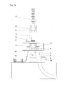
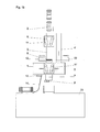
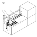
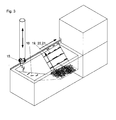
- FIG. 1a A preferred embodiment of a station according to the invention with connection to a pneumatic tube system is shown schematically in FIG Fig. 1a shown; Fig. 1 b shows a variant too Fig. 1a ; Fig. 2 schematically shows a possible connection to an analysis station with feed from below; Fig. 3 schematically shows a possible connection to an analysis station with supply from above.
- Fig. 1a enter pneumatic tube sleeves 2 in a multi-tube transport system, as desired in large hospitals, in a receiving tube 3 of a station 1.
- This station 1 is suitably designed so that they different sleeve lengths and Can handle sleeve shapes.
- the front in the direction of travel pneumatic tube sleeve 2 first passes into the singler 6, where it can be held or moved by the converging in the direction of travel conveyor belts 11 of a belt drive. She is now in waiting position.
- the conveyor belts 11 move a pneumatic tube sleeve 2 slowly in the direction of station 1, so that it encounters a slide 12, which is initially in the closed position.
- the pneumatic tube sleeve 2 is then positioned exactly in this position for receiving in the station 1. If the station 1 is ready for receiving a pneumatic tube 2, the pneumatic tube is released by movement of the slider 12 normal to the direction of travel, and the pneumatic tube 2 enters the station 1.
- the slider 12 can now be closed again, and then leaves the singler 6 a slide further tube post sleeve onto the slide 12.
- an identification unit 9 automatically detects the pneumatic tube 2 and identifies it preferably with the aid of an RFID transponder. In this case, an incorrect transmission can be detected, the transmission time can be determined, and the destination address can be determined. Airtime and other data can be evaluated afterwards, be it for statistical purposes, be it for optimization purposes or similar.
- the identification unit may be integrated in the station 1; Preferably, however, it is arranged immediately in front of the slider 12, where the pneumatic tube sleeve 2 is in the rest position for a short time.
- the conveyor belts 11 ' which are arranged as in the singler 6, and the same way as in the singler 6 initially hold the pneumatic tube 2 to move them later up and down.
- the carriage 5 itself is automatically displaced linearly between at least three positions, namely between a transmission position, a reception position and an ejection position.
- the reception position is in the middle, the ejection position on the left and the transmission position on the right.
- the positions can be chosen as best suited to the space available.
- Actuators, data acquisition, evaluation and control units that initiate the movements of individual parts such as the belt drive or the singler 6 are in the schematic representations in the FIGS. 1a . 1 b . 2 and 3 not shown.
- the Ausladefunktionstician could eg in Fig. 1b as well as against the transmitter ear 4 'be arranged, or it could be provided a fourth position of the carriage for the Ausladefunktionsaku.
- This unloading function unit is a main unit and is off AT 402396 B respectively.
- AT 11306 U1 known, where in each case an automatic sleeve with associated opening mechanism is disclosed.
- a wegschwenkbare control unit 8 which is the Ausladefunktionsussi 7 downstream, checks whether the pneumatic tube 2 is completely emptied.
- the empty sleeve is brought back with the help of the conveyor belts 11 'again completely in the station 1 and the carriage 5 is linearly moved to the send position, so that the pneumatic tube sleeve 2 can be introduced into the transmitter ear 4.
- the return transport is independent of the receiving tube 3.
- This transmitter ear 4 saves waiting times when sending more sleeves to the station.
- This transmitter ear 4 has a further slider 13 installed, which releases the pneumatic tube sleeve 2 for the return transport according to the logically recorded and derived therefrom options.
- Fig. 1 a leads the transmitter ear 4 downwards.
- the respective position of transmitter ear 4 and receiving tube 3 is arbitrary. So could eg in Fig. 1a the position of the Ausladefunktionsaku 7 with the position of the transmitter ear 4 to be reversed, so that in this case the sending position and receiving position of the carriage 6 would be identical and the Ausladeposition of the carriage would be different.
- Fig. 1b differs from Fig. 1a in that a transmitter tube 4 'leading upwards is provided (instead of the transmitter tube 4 leading downwards).
- sending position and receiving position of the carriage 6 are inevitably different.
- it would be conceivable to provide the tube 10 below the transmitter tube 4 ' so that in this case the transmission position of the carriage and the ejection position of the carriage would be identical (as well as the reception position and the unloading position).
- the carriage 5 transfers this pneumatic tube 2 to the opening 10, where the conveyor belts 11 'eject the pneumatic tube 2 on a free slide.
- a free slide 14 may also be provided a basket into which the pneumatic tube sleeves 2 fall.
- Fig. 2 shows the transfer of the sample tubes to the analysis station 22 with supply from below.
- inserts 15 which are removed from a laboratory robot 16 from the open pneumatic tube sleeve 2 and parked.
- the sample tubes are automatically removed individually from the insert 15 and fed to a conveyor belt for sample tube 17.
- Fig. 3 shows a connection to the analysis station 22 with supply from above. This corresponds to the Fig. 1a and 1 b.
- the test tubes fall after opening the pneumatic tube 2 by gravity on a chute 18 and are collected at the lower end of the chute 18.
- a lateral conveyor belt 19 is provided with strips 20 integrally formed normal to the surface of the lateral conveyor belt 19. The strips 20 receive individual sample tubes and lift them up to a linear conveyor belt 21. This transports the tubes to the analysis station 22.
- a station and its connection in the embodiment just described solves the problem of high transmission rates, especially in hospitals at peak times.
Landscapes
- Physics & Mathematics (AREA)
- Health & Medical Sciences (AREA)
- Life Sciences & Earth Sciences (AREA)
- Chemical & Material Sciences (AREA)
- Analytical Chemistry (AREA)
- Biochemistry (AREA)
- General Health & Medical Sciences (AREA)
- General Physics & Mathematics (AREA)
- Immunology (AREA)
- Pathology (AREA)
- Engineering & Computer Science (AREA)
- Fluid Mechanics (AREA)
- Mechanical Engineering (AREA)
- Automatic Analysis And Handling Materials Therefor (AREA)
Applications Claiming Priority (1)
| Application Number | Priority Date | Filing Date | Title |
|---|---|---|---|
| ATGM761/2010U AT12518U1 (de) | 2010-12-13 | 2010-12-13 | Station einer rohrpostanlage |
Publications (3)
| Publication Number | Publication Date |
|---|---|
| EP2463662A2 true EP2463662A2 (fr) | 2012-06-13 |
| EP2463662A3 EP2463662A3 (fr) | 2015-07-01 |
| EP2463662B1 EP2463662B1 (fr) | 2019-07-24 |
Family
ID=45400919
Family Applications (1)
| Application Number | Title | Priority Date | Filing Date |
|---|---|---|---|
| EP11192399.1A Active EP2463662B1 (fr) | 2010-12-13 | 2011-12-07 | Station d'un transporteur à tube |
Country Status (3)
| Country | Link |
|---|---|
| EP (1) | EP2463662B1 (fr) |
| AT (1) | AT12518U1 (fr) |
| DK (1) | DK2463662T3 (fr) |
Cited By (4)
| Publication number | Priority date | Publication date | Assignee | Title |
|---|---|---|---|---|
| CN107200222A (zh) * | 2017-06-09 | 2017-09-26 | 湖南三德科技股份有限公司 | 一种用于物料气动输送系统的自动收发柜 |
| CN113252916A (zh) * | 2021-05-31 | 2021-08-13 | 江苏雷镈智能科技有限公司 | 样品管发送装置及其发送方法 |
| EP3992121A1 (fr) | 2020-10-23 | 2022-05-04 | Ing. Sumetzberger GmbH | Procédé de commande d'une installation d'expédition pneumatique |
| EP4620874A1 (fr) | 2024-03-19 | 2025-09-24 | Ing. Sumetzberger GmbH | Station d'une installation de courrier tubulaire et procédé de distribution d'échantillons |
Families Citing this family (1)
| Publication number | Priority date | Publication date | Assignee | Title |
|---|---|---|---|---|
| AT515548B1 (de) | 2014-07-31 | 2015-10-15 | Hanazeder Erwin | Rohrpoststation zum Entladen von Rohrpostbüchsen |
Citations (4)
| Publication number | Priority date | Publication date | Assignee | Title |
|---|---|---|---|---|
| AT4023B (fr) | 1900-01-22 | 1901-05-10 | Friedrich Pehlke | |
| JP2000019182A (ja) | 1998-06-29 | 2000-01-21 | Tsukioka Yasunobu | ピペットチップセット機 |
| WO2009068574A1 (fr) | 2007-11-30 | 2009-06-04 | Inpeco Ip Ltd. | Appareil automatique pour charger et décharger des tubes de test de matériel biologique dans un système de courrier pneumatique |
| AT11306U1 (de) | 2009-05-27 | 2010-08-15 | Sumetzberger Gmbh Ing | Rohrpostanlage |
Family Cites Families (10)
| Publication number | Priority date | Publication date | Assignee | Title |
|---|---|---|---|---|
| DE204350C (fr) * | ||||
| DE630948C (de) * | 1934-04-19 | 1936-06-09 | Zwietusch E & Co Gmbh | Einrichtung zum Festhalten von Rohrpostbuechsen |
| US2761633A (en) * | 1952-05-31 | 1956-09-04 | Int Standard Electric Corp | Device for slowing down the speed of pneumatic tube dispatch carriers |
| US4047677A (en) * | 1976-09-13 | 1977-09-13 | Ernest Hochradel | Transmit and receive terminal for single tube pneumatic carrier system |
| CH645590A5 (en) * | 1980-06-04 | 1984-10-15 | Hasler Installations Ag | Sending and receiving station for pneumatic mail installations |
| DE3102248A1 (de) * | 1981-01-19 | 1982-09-02 | Siemens AG, 1000 Berlin und 8000 München | Rohrpoststation zum senden, pneumatisch gebremsten empfangen und durchfahren von rohrpostbuechsen |
| DE8101682U1 (de) * | 1981-01-19 | 1985-03-21 | Siemens AG, 1000 Berlin und 8000 München | Rohrpoststation zum senden, pneumatisch gebremsten empfangen und durchfahren von rohrpostbuechsen |
| DE3909478A1 (de) * | 1989-03-22 | 1990-09-27 | Infotronic Vertrieb | Rohrpoststation |
| FR2803584B1 (fr) * | 2000-01-10 | 2002-03-29 | Snef Cote D Azur Sa | Dispositif de convoyage pneumatique de cartouches |
| US7243002B1 (en) * | 2004-03-27 | 2007-07-10 | Translogic Corporation | System and method for carrier identification in a pneumatic tube system |
-
2010
- 2010-12-13 AT ATGM761/2010U patent/AT12518U1/de not_active IP Right Cessation
-
2011
- 2011-12-07 DK DK11192399.1T patent/DK2463662T3/da active
- 2011-12-07 EP EP11192399.1A patent/EP2463662B1/fr active Active
Patent Citations (4)
| Publication number | Priority date | Publication date | Assignee | Title |
|---|---|---|---|---|
| AT4023B (fr) | 1900-01-22 | 1901-05-10 | Friedrich Pehlke | |
| JP2000019182A (ja) | 1998-06-29 | 2000-01-21 | Tsukioka Yasunobu | ピペットチップセット機 |
| WO2009068574A1 (fr) | 2007-11-30 | 2009-06-04 | Inpeco Ip Ltd. | Appareil automatique pour charger et décharger des tubes de test de matériel biologique dans un système de courrier pneumatique |
| AT11306U1 (de) | 2009-05-27 | 2010-08-15 | Sumetzberger Gmbh Ing | Rohrpostanlage |
Cited By (5)
| Publication number | Priority date | Publication date | Assignee | Title |
|---|---|---|---|---|
| CN107200222A (zh) * | 2017-06-09 | 2017-09-26 | 湖南三德科技股份有限公司 | 一种用于物料气动输送系统的自动收发柜 |
| EP3992121A1 (fr) | 2020-10-23 | 2022-05-04 | Ing. Sumetzberger GmbH | Procédé de commande d'une installation d'expédition pneumatique |
| CN113252916A (zh) * | 2021-05-31 | 2021-08-13 | 江苏雷镈智能科技有限公司 | 样品管发送装置及其发送方法 |
| EP4620874A1 (fr) | 2024-03-19 | 2025-09-24 | Ing. Sumetzberger GmbH | Station d'une installation de courrier tubulaire et procédé de distribution d'échantillons |
| AT528139A1 (de) * | 2024-03-19 | 2025-10-15 | Ing Sumetzberger Gmbh | Station einer Rohrpostanlage sowie Verfahren zum Anliefern von Proben |
Also Published As
| Publication number | Publication date |
|---|---|
| EP2463662B1 (fr) | 2019-07-24 |
| EP2463662A3 (fr) | 2015-07-01 |
| AT12518U1 (de) | 2012-07-15 |
| DK2463662T3 (da) | 2019-10-14 |
Similar Documents
| Publication | Publication Date | Title |
|---|---|---|
| EP3581523B1 (fr) | Dispositif et procédé de mise à disposition, en fonction de la demande, de marchandises individuelles pour plusieurs demandes sur un poste d'emballage | |
| EP2463662B1 (fr) | Station d'un transporteur à tube | |
| DE69518293T2 (de) | Maschine und Verfahren zur Sortierung verschiedener Gegenstände unter Verwendung zumindest eines Roboterarms | |
| DE3213119C2 (de) | Verfahren zum Kommissionieren von Stückgut und Vorrichtung zur Durchführung des Verfahrens | |
| EP2675709B1 (fr) | Système de chargement du cargo et méthode de commande d'un convoyeur multiple | |
| DE102020214613A1 (de) | Vorrichtung und Verfahren zum Aufgeben von Transporttaschen in eine Fördertechnik einer Hängeförderanlage sowie derartige Hängeförderanlage | |
| EP2765558A1 (fr) | Dispositif de séparation de pièces de monnaie | |
| DE102018105911A1 (de) | Produktionssystem | |
| EP2923974B1 (fr) | Dispositif et procédé d'agencement peu encombrant de marchandises suspendues | |
| EP3623060B1 (fr) | Procédé de tri d'objets ainsi qu'installation de tri | |
| DE102014203118A1 (de) | Schaltbare Weiche zum Beeinflussen eines Flusses von Einzelwaren in einem Fördersystem, Fördersystem mit einer derartigen schaltbaren Weiche sowie Verfahren zum Schalten einer derartigen schaltbaren Weiche | |
| DE102011000819A1 (de) | Ladesystem für ein Flugzeug und Verfahren zur Förderung eines Frachtstücks auf einem Frachtdeck | |
| DE102019108887A1 (de) | Verfahren zum Prüfen von Lebensmittelpackungen | |
| EP2390204B1 (fr) | Système complétant un stockage de petits articles | |
| DE102019205185A1 (de) | Rohrpoststation mit einem Werkzeugwechsler | |
| EP3166736B1 (fr) | Système de manutention pour des bouteilles consignées | |
| DE102008037659A1 (de) | Versandregal vorzugsweise in einer Kommissionieranlage | |
| EP3325384A1 (fr) | Dispositif de séparation de marchandises en vrac | |
| EP2088096A1 (fr) | Dispositif d'insertion automatisée pour un stock de pharmacie | |
| DE102023203126A1 (de) | Beladeverfahren und Beladestation für Förderbehälter | |
| EP2846313A1 (fr) | Dispositif de séparation de pièces de monnaie | |
| DE19921570A1 (de) | Vorrichtung und Verfahren zur Verarbeitung von Geld | |
| EP4596320A1 (fr) | Véhicule de transport de marchandises de détail et procédé de fonctionnement d'un véhicule de transport de marchandises de détail | |
| EP2083401A1 (fr) | Automate de reprise pour bouteilles consignées | |
| EP4446255A1 (fr) | Convoyeur aérien pour assembler des articles en ordre de tri et procédé correspondant |
Legal Events
| Date | Code | Title | Description |
|---|---|---|---|
| PUAI | Public reference made under article 153(3) epc to a published international application that has entered the european phase |
Free format text: ORIGINAL CODE: 0009012 |
|
| AK | Designated contracting states |
Kind code of ref document: A2 Designated state(s): AL AT BE BG CH CY CZ DE DK EE ES FI FR GB GR HR HU IE IS IT LI LT LU LV MC MK MT NL NO PL PT RO RS SE SI SK SM TR |
|
| AX | Request for extension of the european patent |
Extension state: BA ME |
|
| PUAL | Search report despatched |
Free format text: ORIGINAL CODE: 0009013 |
|
| AK | Designated contracting states |
Kind code of ref document: A3 Designated state(s): AL AT BE BG CH CY CZ DE DK EE ES FI FR GB GR HR HU IE IS IT LI LT LU LV MC MK MT NL NO PL PT RO RS SE SI SK SM TR |
|
| AX | Request for extension of the european patent |
Extension state: BA ME |
|
| RIC1 | Information provided on ipc code assigned before grant |
Ipc: B65G 51/32 20060101ALI20150522BHEP Ipc: G01N 35/00 20060101ALN20150522BHEP Ipc: B65G 51/30 20060101AFI20150522BHEP Ipc: G01N 35/04 20060101ALN20150522BHEP |
|
| 17P | Request for examination filed |
Effective date: 20151124 |
|
| RBV | Designated contracting states (corrected) |
Designated state(s): AL AT BE BG CH CY CZ DE DK EE ES FI FR GB GR HR HU IE IS IT LI LT LU LV MC MK MT NL NO PL PT RO RS SE SI SK SM TR |
|
| 17Q | First examination report despatched |
Effective date: 20160415 |
|
| STAA | Information on the status of an ep patent application or granted ep patent |
Free format text: STATUS: EXAMINATION IS IN PROGRESS |
|
| REG | Reference to a national code |
Ref country code: DE Ref legal event code: R079 Ref document number: 502011015928 Country of ref document: DE Free format text: PREVIOUS MAIN CLASS: G01N0035040000 Ipc: B65G0051300000 |
|
| GRAP | Despatch of communication of intention to grant a patent |
Free format text: ORIGINAL CODE: EPIDOSNIGR1 |
|
| STAA | Information on the status of an ep patent application or granted ep patent |
Free format text: STATUS: GRANT OF PATENT IS INTENDED |
|
| RIC1 | Information provided on ipc code assigned before grant |
Ipc: G01N 35/00 20060101ALN20190123BHEP Ipc: B65G 51/32 20060101ALI20190123BHEP Ipc: G01N 35/04 20060101ALN20190123BHEP Ipc: B65G 51/30 20060101AFI20190123BHEP |
|
| INTG | Intention to grant announced |
Effective date: 20190215 |
|
| GRAS | Grant fee paid |
Free format text: ORIGINAL CODE: EPIDOSNIGR3 |
|
| GRAA | (expected) grant |
Free format text: ORIGINAL CODE: 0009210 |
|
| STAA | Information on the status of an ep patent application or granted ep patent |
Free format text: STATUS: THE PATENT HAS BEEN GRANTED |
|
| AK | Designated contracting states |
Kind code of ref document: B1 Designated state(s): AL AT BE BG CH CY CZ DE DK EE ES FI FR GB GR HR HU IE IS IT LI LT LU LV MC MK MT NL NO PL PT RO RS SE SI SK SM TR |
|
| REG | Reference to a national code |
Ref country code: GB Ref legal event code: FG4D Free format text: NOT ENGLISH |
|
| REG | Reference to a national code |
Ref country code: CH Ref legal event code: EP |
|
| REG | Reference to a national code |
Ref country code: DE Ref legal event code: R096 Ref document number: 502011015928 Country of ref document: DE |
|
| REG | Reference to a national code |
Ref country code: AT Ref legal event code: REF Ref document number: 1157917 Country of ref document: AT Kind code of ref document: T Effective date: 20190815 |
|
| REG | Reference to a national code |
Ref country code: IE Ref legal event code: FG4D Free format text: LANGUAGE OF EP DOCUMENT: GERMAN |
|
| REG | Reference to a national code |
Ref country code: DK Ref legal event code: T3 Effective date: 20191011 |
|
| REG | Reference to a national code |
Ref country code: SE Ref legal event code: TRGR |
|
| REG | Reference to a national code |
Ref country code: NL Ref legal event code: MP Effective date: 20190724 |
|
| REG | Reference to a national code |
Ref country code: LT Ref legal event code: MG4D |
|
| PG25 | Lapsed in a contracting state [announced via postgrant information from national office to epo] |
Ref country code: FI Free format text: LAPSE BECAUSE OF FAILURE TO SUBMIT A TRANSLATION OF THE DESCRIPTION OR TO PAY THE FEE WITHIN THE PRESCRIBED TIME-LIMIT Effective date: 20190724 Ref country code: LT Free format text: LAPSE BECAUSE OF FAILURE TO SUBMIT A TRANSLATION OF THE DESCRIPTION OR TO PAY THE FEE WITHIN THE PRESCRIBED TIME-LIMIT Effective date: 20190724 Ref country code: HR Free format text: LAPSE BECAUSE OF FAILURE TO SUBMIT A TRANSLATION OF THE DESCRIPTION OR TO PAY THE FEE WITHIN THE PRESCRIBED TIME-LIMIT Effective date: 20190724 Ref country code: BG Free format text: LAPSE BECAUSE OF FAILURE TO SUBMIT A TRANSLATION OF THE DESCRIPTION OR TO PAY THE FEE WITHIN THE PRESCRIBED TIME-LIMIT Effective date: 20191024 Ref country code: NO Free format text: LAPSE BECAUSE OF FAILURE TO SUBMIT A TRANSLATION OF THE DESCRIPTION OR TO PAY THE FEE WITHIN THE PRESCRIBED TIME-LIMIT Effective date: 20191024 Ref country code: NL Free format text: LAPSE BECAUSE OF FAILURE TO SUBMIT A TRANSLATION OF THE DESCRIPTION OR TO PAY THE FEE WITHIN THE PRESCRIBED TIME-LIMIT Effective date: 20190724 Ref country code: PT Free format text: LAPSE BECAUSE OF FAILURE TO SUBMIT A TRANSLATION OF THE DESCRIPTION OR TO PAY THE FEE WITHIN THE PRESCRIBED TIME-LIMIT Effective date: 20191125 |
|
| PG25 | Lapsed in a contracting state [announced via postgrant information from national office to epo] |
Ref country code: ES Free format text: LAPSE BECAUSE OF FAILURE TO SUBMIT A TRANSLATION OF THE DESCRIPTION OR TO PAY THE FEE WITHIN THE PRESCRIBED TIME-LIMIT Effective date: 20190724 Ref country code: AL Free format text: LAPSE BECAUSE OF FAILURE TO SUBMIT A TRANSLATION OF THE DESCRIPTION OR TO PAY THE FEE WITHIN THE PRESCRIBED TIME-LIMIT Effective date: 20190724 Ref country code: LV Free format text: LAPSE BECAUSE OF FAILURE TO SUBMIT A TRANSLATION OF THE DESCRIPTION OR TO PAY THE FEE WITHIN THE PRESCRIBED TIME-LIMIT Effective date: 20190724 Ref country code: IS Free format text: LAPSE BECAUSE OF FAILURE TO SUBMIT A TRANSLATION OF THE DESCRIPTION OR TO PAY THE FEE WITHIN THE PRESCRIBED TIME-LIMIT Effective date: 20191124 Ref country code: RS Free format text: LAPSE BECAUSE OF FAILURE TO SUBMIT A TRANSLATION OF THE DESCRIPTION OR TO PAY THE FEE WITHIN THE PRESCRIBED TIME-LIMIT Effective date: 20190724 Ref country code: GR Free format text: LAPSE BECAUSE OF FAILURE TO SUBMIT A TRANSLATION OF THE DESCRIPTION OR TO PAY THE FEE WITHIN THE PRESCRIBED TIME-LIMIT Effective date: 20191025 |
|
| PG25 | Lapsed in a contracting state [announced via postgrant information from national office to epo] |
Ref country code: TR Free format text: LAPSE BECAUSE OF FAILURE TO SUBMIT A TRANSLATION OF THE DESCRIPTION OR TO PAY THE FEE WITHIN THE PRESCRIBED TIME-LIMIT Effective date: 20190724 |
|
| PG25 | Lapsed in a contracting state [announced via postgrant information from national office to epo] |
Ref country code: PL Free format text: LAPSE BECAUSE OF FAILURE TO SUBMIT A TRANSLATION OF THE DESCRIPTION OR TO PAY THE FEE WITHIN THE PRESCRIBED TIME-LIMIT Effective date: 20190724 Ref country code: EE Free format text: LAPSE BECAUSE OF FAILURE TO SUBMIT A TRANSLATION OF THE DESCRIPTION OR TO PAY THE FEE WITHIN THE PRESCRIBED TIME-LIMIT Effective date: 20190724 Ref country code: RO Free format text: LAPSE BECAUSE OF FAILURE TO SUBMIT A TRANSLATION OF THE DESCRIPTION OR TO PAY THE FEE WITHIN THE PRESCRIBED TIME-LIMIT Effective date: 20190724 |
|
| PG25 | Lapsed in a contracting state [announced via postgrant information from national office to epo] |
Ref country code: SK Free format text: LAPSE BECAUSE OF FAILURE TO SUBMIT A TRANSLATION OF THE DESCRIPTION OR TO PAY THE FEE WITHIN THE PRESCRIBED TIME-LIMIT Effective date: 20190724 Ref country code: IS Free format text: LAPSE BECAUSE OF FAILURE TO SUBMIT A TRANSLATION OF THE DESCRIPTION OR TO PAY THE FEE WITHIN THE PRESCRIBED TIME-LIMIT Effective date: 20200224 Ref country code: SM Free format text: LAPSE BECAUSE OF FAILURE TO SUBMIT A TRANSLATION OF THE DESCRIPTION OR TO PAY THE FEE WITHIN THE PRESCRIBED TIME-LIMIT Effective date: 20190724 Ref country code: CZ Free format text: LAPSE BECAUSE OF FAILURE TO SUBMIT A TRANSLATION OF THE DESCRIPTION OR TO PAY THE FEE WITHIN THE PRESCRIBED TIME-LIMIT Effective date: 20190724 |
|
| REG | Reference to a national code |
Ref country code: DE Ref legal event code: R097 Ref document number: 502011015928 Country of ref document: DE |
|
| PLBE | No opposition filed within time limit |
Free format text: ORIGINAL CODE: 0009261 |
|
| STAA | Information on the status of an ep patent application or granted ep patent |
Free format text: STATUS: NO OPPOSITION FILED WITHIN TIME LIMIT |
|
| PG2D | Information on lapse in contracting state deleted |
Ref country code: IS |
|
| REG | Reference to a national code |
Ref country code: CH Ref legal event code: PL |
|
| 26N | No opposition filed |
Effective date: 20200603 |
|
| REG | Reference to a national code |
Ref country code: BE Ref legal event code: MM Effective date: 20191231 |
|
| PG25 | Lapsed in a contracting state [announced via postgrant information from national office to epo] |
Ref country code: SI Free format text: LAPSE BECAUSE OF FAILURE TO SUBMIT A TRANSLATION OF THE DESCRIPTION OR TO PAY THE FEE WITHIN THE PRESCRIBED TIME-LIMIT Effective date: 20190724 Ref country code: MC Free format text: LAPSE BECAUSE OF FAILURE TO SUBMIT A TRANSLATION OF THE DESCRIPTION OR TO PAY THE FEE WITHIN THE PRESCRIBED TIME-LIMIT Effective date: 20190724 |
|
| GBPC | Gb: european patent ceased through non-payment of renewal fee |
Effective date: 20191207 |
|
| PG25 | Lapsed in a contracting state [announced via postgrant information from national office to epo] |
Ref country code: GB Free format text: LAPSE BECAUSE OF NON-PAYMENT OF DUE FEES Effective date: 20191207 Ref country code: LU Free format text: LAPSE BECAUSE OF NON-PAYMENT OF DUE FEES Effective date: 20191207 Ref country code: IE Free format text: LAPSE BECAUSE OF NON-PAYMENT OF DUE FEES Effective date: 20191207 |
|
| PG25 | Lapsed in a contracting state [announced via postgrant information from national office to epo] |
Ref country code: LI Free format text: LAPSE BECAUSE OF NON-PAYMENT OF DUE FEES Effective date: 20191231 Ref country code: CH Free format text: LAPSE BECAUSE OF NON-PAYMENT OF DUE FEES Effective date: 20191231 Ref country code: BE Free format text: LAPSE BECAUSE OF NON-PAYMENT OF DUE FEES Effective date: 20191231 |
|
| PG25 | Lapsed in a contracting state [announced via postgrant information from national office to epo] |
Ref country code: CY Free format text: LAPSE BECAUSE OF FAILURE TO SUBMIT A TRANSLATION OF THE DESCRIPTION OR TO PAY THE FEE WITHIN THE PRESCRIBED TIME-LIMIT Effective date: 20190724 |
|
| PG25 | Lapsed in a contracting state [announced via postgrant information from national office to epo] |
Ref country code: HU Free format text: LAPSE BECAUSE OF FAILURE TO SUBMIT A TRANSLATION OF THE DESCRIPTION OR TO PAY THE FEE WITHIN THE PRESCRIBED TIME-LIMIT; INVALID AB INITIO Effective date: 20111207 Ref country code: MT Free format text: LAPSE BECAUSE OF FAILURE TO SUBMIT A TRANSLATION OF THE DESCRIPTION OR TO PAY THE FEE WITHIN THE PRESCRIBED TIME-LIMIT Effective date: 20190724 Ref country code: FR Free format text: LAPSE BECAUSE OF NON-PAYMENT OF DUE FEES Effective date: 20191231 |
|
| PG25 | Lapsed in a contracting state [announced via postgrant information from national office to epo] |
Ref country code: MK Free format text: LAPSE BECAUSE OF FAILURE TO SUBMIT A TRANSLATION OF THE DESCRIPTION OR TO PAY THE FEE WITHIN THE PRESCRIBED TIME-LIMIT Effective date: 20190724 |
|
| REG | Reference to a national code |
Ref country code: DE Ref legal event code: R082 Ref document number: 502011015928 Country of ref document: DE Representative=s name: SZYNKA SMORODIN PATENTANWAELTE PARTNERSCHAFT M, DE |
|
| PGFP | Annual fee paid to national office [announced via postgrant information from national office to epo] |
Ref country code: DE Payment date: 20251113 Year of fee payment: 15 |
|
| PGFP | Annual fee paid to national office [announced via postgrant information from national office to epo] |
Ref country code: AT Payment date: 20251223 Year of fee payment: 15 |
|
| PGFP | Annual fee paid to national office [announced via postgrant information from national office to epo] |
Ref country code: IT Payment date: 20251202 Year of fee payment: 15 Ref country code: DK Payment date: 20251114 Year of fee payment: 15 |
|
| PGFP | Annual fee paid to national office [announced via postgrant information from national office to epo] |
Ref country code: SE Payment date: 20251114 Year of fee payment: 15 |