EP2463688A2 - Procédé de détection d'objets à l'aide d'une grille lumineuse - Google Patents
Procédé de détection d'objets à l'aide d'une grille lumineuse Download PDFInfo
- Publication number
- EP2463688A2 EP2463688A2 EP11190459A EP11190459A EP2463688A2 EP 2463688 A2 EP2463688 A2 EP 2463688A2 EP 11190459 A EP11190459 A EP 11190459A EP 11190459 A EP11190459 A EP 11190459A EP 2463688 A2 EP2463688 A2 EP 2463688A2
- Authority
- EP
- European Patent Office
- Prior art keywords
- receiver
- transmitter
- matrix
- activated
- transmitters
- Prior art date
- Legal status (The legal status is an assumption and is not a legal conclusion. Google has not performed a legal analysis and makes no representation as to the accuracy of the status listed.)
- Granted
Links
- 238000000034 method Methods 0.000 title claims abstract description 14
- 238000011156 evaluation Methods 0.000 claims abstract description 14
- 238000001514 detection method Methods 0.000 claims description 34
- 238000012544 monitoring process Methods 0.000 claims description 5
- 238000003491 array Methods 0.000 abstract description 4
- 238000010586 diagram Methods 0.000 description 5
- 230000004913 activation Effects 0.000 description 4
- 230000005540 biological transmission Effects 0.000 description 4
- 239000011159 matrix material Substances 0.000 description 2
- 238000005259 measurement Methods 0.000 description 2
- 241001136792 Alle Species 0.000 description 1
- 230000015572 biosynthetic process Effects 0.000 description 1
- 238000010276 construction Methods 0.000 description 1
- 230000001419 dependent effect Effects 0.000 description 1
- 238000013461 design Methods 0.000 description 1
- 238000011161 development Methods 0.000 description 1
- 230000018109 developmental process Effects 0.000 description 1
- 230000009977 dual effect Effects 0.000 description 1
- 238000005516 engineering process Methods 0.000 description 1
- 238000005755 formation reaction Methods 0.000 description 1
- 230000035945 sensitivity Effects 0.000 description 1
Images



Classifications
-
- G—PHYSICS
- G01—MEASURING; TESTING
- G01V—GEOPHYSICS; GRAVITATIONAL MEASUREMENTS; DETECTING MASSES OR OBJECTS; TAGS
- G01V8/00—Prospecting or detecting by optical means
- G01V8/10—Detecting, e.g. by using light barriers
- G01V8/20—Detecting, e.g. by using light barriers using multiple transmitters or receivers
Definitions
- the invention relates to a light grid and a method for detecting objects by means of a light grid.
- Known light grids comprise a transmitter unit with a linear arrangement of transmitters emitting light beams and a receiver unit with a linear arrangement of receivers receiving light beams.
- a transmitter and an associated receiver form a beam axis.
- the beam axes of the light grid are cyclically activated one after the other.
- the transmitter unit and receiver unit are arranged at opposite edges of a surveillance area. When the monitoring area is free, the light beams of the transmitters of all the beam axes pass unhindered to the assigned receivers.
- an object intervention at least one beam axis is interrupted.
- a binary switching signal is generated whose switching states indicate whether or not an object is located in the monitored area.
- Such light grids are used for example in the field of safety technology.
- the transmitter unit and receiver unit can be oriented horizontally or horizontally. Irrespective of this orientation, it is only possible to a limited extent to acquire complex object formations, in particular geometry data, with such light grids.
- the invention has for its object to provide a light grid of the type mentioned, by means of which a reliable object detection is made possible with low design complexity with the lowest possible response times.
- the invention relates to a method with which the actual received signals of the receiver are compared with predetermined reference values for object detection.
- the beam axes formed by individual transmitters and receivers are cyclically activated one after the other.
- the areas of the matrix-like arrangements of the transmitters and receivers activated for the object detections are predetermined by parameterizations.
- the areas of the matrix-like arrangements of the transmitters and receivers activated for the object detections are varied independently of previously determined measured values of the light grid.
- the regions of the matrix-shaped arrangements of the transmitters and receivers activated for the object detections are generally specified as a function of characteristics of the objects to be detected.
- the respectively activated regions of the transmitter and receiver arrangements are thereby optimally adapted to the respective object detections to be performed, in such a way that the object structures to be detected can be completely detected with the smallest possible sizes of activated regions of transmitters and receivers.
- the detection sensitivity of the light grid can be further increased by comparing the current received signals of the receiver with predetermined reference values for object detection.
- non-activated areas of transmitters are used as display elements in the object detections.
- the transmitter of organic light emitting diodes and the receiver formed by organic photodiodes are particularly advantageous.
- the light grid according to the invention is used particularly advantageously in areas where flow processes must be monitored and objects must be detected with regard to their positions, sizes, directions of movement and speeds.
- FIG. 1 shows a block diagram of an embodiment of the light grid according to the invention 1 for object detection in a surveillance area.
- the light grid 1 comprises a transmitter unit 1a and a receiver unit 1b, which are arranged on opposite edges of the monitoring area.
- the light grid 1 comprises a transmitter array 2 with a matrix-like arrangement of transmitters 2 a (shown in FIG. 2 ), wherein the individual transmitter 2a consist of organic light emitting diodes (OLED).
- the light beams 3 emitted by the transmitters 2a reach a receiver array 4 consisting of a matrix-like arrangement of receivers 4a (shown in FIG. 2 ), each consisting of organic photodiodes (OPD).
- OPD organic photodiodes
- the transmitter arrays 2 and receiver arrays 4 are connected via leads 7a, 7b to an evaluation and control unit 8. This takes over the control of the transmitter 2a and receiver 4a and the evaluation of the received signals of the receiver 4a.
- an evaluation and control unit 8 depending on stored parameter values or depending on previously determined measured values, selectively selective regions of the transmitter array 2 and receiver arrays 4 are activated. Within the activated regions, individual beam axes, that is to say individual transmitters 2a and receivers 4a assigned to them, are cyclically activated one after the other one after the other. Then the received signals 4a of the activated receivers are evaluated for object detection. As an object message, a binary switching signal can be generated whose switching states indicate whether generally an object 6 or specifically a particular particular safety-critical object 6 is in the surveillance area or not.
- the switching signal is output via a switching output 9. More complex object messages are output via a serial interface 10, which also serves to read in parameter values.
- a reference value comparison can be carried out, that is to say currently detected received signals are compared with reference values stored in the evaluation and control unit 8.
- FIG. 2 shows the geometric assignment of the transmitter array 2 and the receiver array 4 of the light grid 1 according to FIG. 1 to an object 6, which moves on a conveyor belt 11.
- the transport direction runs in the x direction.
- a small activated area of the transmitter array 2 to activate the transmitters 2a of the range x1, y1 one after the other and to compare the received signals with the reference receive signal at free distance with only one receiver 4a.
- the throughput time is limited to the sum of a few activation cycles of the transmitter 2a and the reading of the associated received signals for the measurement.
- the query of the entire array with, for example, 100 x 100 transmitters 2a would result in a cycle time of 100 ms.
- the switching time for the switching position can be calculated with the aid of the determined movement data and a switching signal can be output.
- the transmitter array 2 can be reduced to one to two transmitter lines and the receiver array 4 to a few discrete receivers 4a.
- FIG. 3 shows the transmitter array 2 of the light grid 1 according to the Figures 1 and 2 with the individual transmitters 2a, which are each followed by transmitting optics 12 so that a sufficient area is illuminated on the receiver array 4.
- receive optics in front of each receiver 4a of the receiver array 4 ensure that the area of the transmitter array 2 in question can be detected.
- the cross beams can be activated, wherein an activated transmitter 2a is not only detected by the directly opposite receiver 4a, but also by a staggered receiver 4a.
- FIG. 4 shows the transmitter 2a in the xy plane with the downstream transmitter optics.
- the matrix pitch of the transmission optics 12 is chosen to be somewhat smaller than the matrix pitch of the transmitters 2a, whereby the transmit beams remain in the area of the receiver array 4 despite scattering.
- the second lowest beam axis is activated, which now also quickly reports the object position shifted by dx1. Then the third lowest beam axis, and so on.
- FIG. 6 shows how the object velocity v1 is calculated from the slope triangle dx1 / dt1. From the response, ie interruption of the beam axis results in the provisional time difference dt1.
- Texts or symbols can be displayed on the non-active area of the transmitter array 2.
- a switched on to the text display transmitter 2a does not disturb the receiver 4a, since the constant light is suppressed electronically on the receiving side.
- an already switched on transmitter 2a can be blanked.
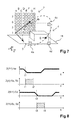
- FIG. 7 shows the second embodiment for the detection of the object geometries of largely rectangular objects 6.
- A1 to A8 two vertically extending transmitter rows
- H1 and H8 a redundant object information can be obtained to obtain more accurate geometry data.
- FIG. 8 shows diagrams for the time sequences of object recognition and object height detection.
- the object leading edge is detected a first time at time t1 and at exactly the same object height at time t3 and therefrom calculates the object speed.
- the object height, or the position of the object upper edges between t1 and t2 can be determined.
- about the object trailing edge more redundant information can be obtained.
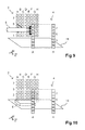
- FIG. 9 shows the third embodiment for the detection of protruding in the x direction parts of the object 6 by means of the light grid 1. With the aid of cross beams of the light grid 1, the object diameter and the position in the y direction are determined.
- FIG. 10 shows the fourth embodiment for the detection of flat objects 6 on the conveyor belt 11.
- the conveyor belt 11 is permanently detected by at least one beam axis.
- a flat object 6 can be detected on the conveyor belt 11 and identified with respect to its length.
- FIG. 11 shows the fifth embodiment for the detection of small objects 6, which fall through the detection area of the transmitter array 2 and the receiver array 4. This will, as in FIG. 11a shown, in the first step, the uppermost transmission line activated until the object 6 is immersed and the corresponding transmission column is determined. After that can be done accordingly FIG. 11b be tracked with few cross beams, the position of the falling object 6 in space.
Landscapes
- Physics & Mathematics (AREA)
- Life Sciences & Earth Sciences (AREA)
- General Life Sciences & Earth Sciences (AREA)
- General Physics & Mathematics (AREA)
- Geophysics (AREA)
- Geophysics And Detection Of Objects (AREA)
Applications Claiming Priority (1)
| Application Number | Priority Date | Filing Date | Title |
|---|---|---|---|
| DE201010054315 DE102010054315A1 (de) | 2010-12-13 | 2010-12-13 | Verfahren zur Erfassung von Objekten mittels eines Lichtglitters |
Publications (3)
| Publication Number | Publication Date |
|---|---|
| EP2463688A2 true EP2463688A2 (fr) | 2012-06-13 |
| EP2463688A3 EP2463688A3 (fr) | 2015-01-21 |
| EP2463688B1 EP2463688B1 (fr) | 2019-08-14 |
Family
ID=45217266
Family Applications (1)
| Application Number | Title | Priority Date | Filing Date |
|---|---|---|---|
| EP11190459.5A Ceased EP2463688B1 (fr) | 2010-12-13 | 2011-11-24 | Procédé de détection d'objets à l'aide d'une grille lumineuse |
Country Status (2)
| Country | Link |
|---|---|
| EP (1) | EP2463688B1 (fr) |
| DE (1) | DE102010054315A1 (fr) |
Cited By (1)
| Publication number | Priority date | Publication date | Assignee | Title |
|---|---|---|---|---|
| EP4123210A1 (fr) * | 2021-07-23 | 2023-01-25 | Markem-Imaje Corporation | Procédé et appareil pour caractériser des objets à l'aide d'un réseau luminescent |
Families Citing this family (1)
| Publication number | Priority date | Publication date | Assignee | Title |
|---|---|---|---|---|
| DE102015105150A1 (de) * | 2015-04-02 | 2016-10-06 | Sick Ag | Verfahren zum Betrieb eines optoelektronischen Sensors und optoelektronischer Sensor |
Family Cites Families (6)
| Publication number | Priority date | Publication date | Assignee | Title |
|---|---|---|---|---|
| DE4305559A1 (de) * | 1993-02-24 | 1994-08-25 | Hans Schiesl | Anordnung und Verfahren zur Konturerkennung von Gegenständen |
| US7180441B2 (en) * | 2004-04-14 | 2007-02-20 | Safeview, Inc. | Multi-sensor surveillance portal |
| JP4751752B2 (ja) * | 2006-03-31 | 2011-08-17 | 株式会社本田電子技研 | 自動ドア用反射型センサ |
| ITMO20060219A1 (it) * | 2006-07-06 | 2008-01-07 | Datasensor Spa | Barriera di sicurezza |
| US20080074652A1 (en) * | 2006-09-15 | 2008-03-27 | Fouquet Julie E | Retroreflector-based system and method for detecting intrusion into a restricted area |
| CA2715184C (fr) * | 2008-03-19 | 2013-02-12 | Nabtesco Corporation | Capteur pour porte automatique |
-
2010
- 2010-12-13 DE DE201010054315 patent/DE102010054315A1/de not_active Withdrawn
-
2011
- 2011-11-24 EP EP11190459.5A patent/EP2463688B1/fr not_active Ceased
Non-Patent Citations (1)
| Title |
|---|
| None |
Cited By (3)
| Publication number | Priority date | Publication date | Assignee | Title |
|---|---|---|---|---|
| EP4123210A1 (fr) * | 2021-07-23 | 2023-01-25 | Markem-Imaje Corporation | Procédé et appareil pour caractériser des objets à l'aide d'un réseau luminescent |
| US20230033635A1 (en) * | 2021-07-23 | 2023-02-02 | Markem-Imaje Corporation | Method and Apparatus for Characterizing Objects Using a Light-Emitting Array |
| US12276493B2 (en) | 2021-07-23 | 2025-04-15 | Markem-Imaje Corporation | Method and apparatus for characterizing objects using a light-emitting array |
Also Published As
| Publication number | Publication date |
|---|---|
| DE102010054315A1 (de) | 2012-06-14 |
| EP2463688B1 (fr) | 2019-08-14 |
| EP2463688A3 (fr) | 2015-01-21 |
Similar Documents
| Publication | Publication Date | Title |
|---|---|---|
| EP1046925B1 (fr) | Dispositif optoélectronique | |
| EP3318895A1 (fr) | Dispositif et procédé de réception d'une impulsion lumineuse réfléchie dans un système lidar | |
| DE102012101368B4 (de) | Lichtvorhang | |
| EP2071363B1 (fr) | Barrière lumineuse et son procédé de fonctionnement | |
| DE102012101369B4 (de) | Lichtvorhang | |
| WO2019197243A1 (fr) | Procédé de mise en œuvre d'un processus de mesure | |
| EP3499267A1 (fr) | Capteur photoélectrique trigonométrique | |
| DE102007043378B4 (de) | Lichtgitter | |
| EP3220164A1 (fr) | Procède de fonctionnement d'un capteur ecartométrique de surveillance et capteur ecartométrique de surveillance | |
| EP2463688B1 (fr) | Procédé de détection d'objets à l'aide d'une grille lumineuse | |
| EP2306145B1 (fr) | Capteur optique | |
| EP2672296B1 (fr) | Rideau lumineux | |
| EP3385721B1 (fr) | Barrière lumineuse | |
| DE102017119283B4 (de) | Sensorsystem | |
| EP3841392A1 (fr) | Dispositif lidar à analyse accélérée de la durée d'exécution | |
| DE102013018801A1 (de) | Verfahren und Vorrichtung zum optischen Bestimmen von Abständen zu Objekten, insbesondere zu Komponenten von Regalen, in einem Überwachungsbereich | |
| EP4092449B1 (fr) | Agencement de barrière lumineuse et procédé de détection des objets dans une zone de surveillance | |
| DE202011100974U1 (de) | Optisches Sensorsystem | |
| EP4202494A1 (fr) | Détection optique d'un objet selon le principe de triangulation | |
| DE102010061194A1 (de) | Optoelektronischer Sensor | |
| EP1772753B1 (fr) | Procédé d'utilisation d'un rideau lumineux | |
| EP3168655A1 (fr) | Barrières lumineuses et procédé de détection d'objets | |
| EP3637155B1 (fr) | Système de barrière lumineuse | |
| EP3872526B1 (fr) | Dispositif de surveillance d'une zone protégée | |
| EP3869241B1 (fr) | Agencement de barrières lumineuses |
Legal Events
| Date | Code | Title | Description |
|---|---|---|---|
| PUAI | Public reference made under article 153(3) epc to a published international application that has entered the european phase |
Free format text: ORIGINAL CODE: 0009012 |
|
| AK | Designated contracting states |
Kind code of ref document: A2 Designated state(s): AL AT BE BG CH CY CZ DE DK EE ES FI FR GB GR HR HU IE IS IT LI LT LU LV MC MK MT NL NO PL PT RO RS SE SI SK SM TR |
|
| AX | Request for extension of the european patent |
Extension state: BA ME |
|
| PUAL | Search report despatched |
Free format text: ORIGINAL CODE: 0009013 |
|
| AK | Designated contracting states |
Kind code of ref document: A3 Designated state(s): AL AT BE BG CH CY CZ DE DK EE ES FI FR GB GR HR HU IE IS IT LI LT LU LV MC MK MT NL NO PL PT RO RS SE SI SK SM TR |
|
| AX | Request for extension of the european patent |
Extension state: BA ME |
|
| RIC1 | Information provided on ipc code assigned before grant |
Ipc: G01V 8/20 20060101AFI20141217BHEP |
|
| 17P | Request for examination filed |
Effective date: 20150209 |
|
| RBV | Designated contracting states (corrected) |
Designated state(s): AL AT BE BG CH CY CZ DE DK EE ES FI FR GB GR HR HU IE IS IT LI LT LU LV MC MK MT NL NO PL PT RO RS SE SI SK SM TR |
|
| STAA | Information on the status of an ep patent application or granted ep patent |
Free format text: STATUS: EXAMINATION IS IN PROGRESS |
|
| 17Q | First examination report despatched |
Effective date: 20171117 |
|
| GRAP | Despatch of communication of intention to grant a patent |
Free format text: ORIGINAL CODE: EPIDOSNIGR1 |
|
| STAA | Information on the status of an ep patent application or granted ep patent |
Free format text: STATUS: GRANT OF PATENT IS INTENDED |
|
| INTG | Intention to grant announced |
Effective date: 20190125 |
|
| GRAS | Grant fee paid |
Free format text: ORIGINAL CODE: EPIDOSNIGR3 |
|
| RBV | Designated contracting states (corrected) |
Designated state(s): DE |
|
| GRAA | (expected) grant |
Free format text: ORIGINAL CODE: 0009210 |
|
| STAA | Information on the status of an ep patent application or granted ep patent |
Free format text: STATUS: THE PATENT HAS BEEN GRANTED |
|
| AK | Designated contracting states |
Kind code of ref document: B1 Designated state(s): DE |
|
| REG | Reference to a national code |
Ref country code: DE Ref legal event code: R096 Ref document number: 502011015995 Country of ref document: DE |
|
| REG | Reference to a national code |
Ref country code: DE Ref legal event code: R097 Ref document number: 502011015995 Country of ref document: DE |
|
| PLBE | No opposition filed within time limit |
Free format text: ORIGINAL CODE: 0009261 |
|
| STAA | Information on the status of an ep patent application or granted ep patent |
Free format text: STATUS: NO OPPOSITION FILED WITHIN TIME LIMIT |
|
| 26N | No opposition filed |
Effective date: 20200603 |
|
| PGFP | Annual fee paid to national office [announced via postgrant information from national office to epo] |
Ref country code: DE Payment date: 20221109 Year of fee payment: 12 |
|
| REG | Reference to a national code |
Ref country code: DE Ref legal event code: R119 Ref document number: 502011015995 Country of ref document: DE |
|
| PG25 | Lapsed in a contracting state [announced via postgrant information from national office to epo] |
Ref country code: DE Free format text: LAPSE BECAUSE OF NON-PAYMENT OF DUE FEES Effective date: 20240601 |
|
| PG25 | Lapsed in a contracting state [announced via postgrant information from national office to epo] |
Ref country code: DE Free format text: LAPSE BECAUSE OF NON-PAYMENT OF DUE FEES Effective date: 20240601 |