EP3637155B1 - Système de barrière lumineuse - Google Patents
Système de barrière lumineuse Download PDFInfo
- Publication number
- EP3637155B1 EP3637155B1 EP19190638.7A EP19190638A EP3637155B1 EP 3637155 B1 EP3637155 B1 EP 3637155B1 EP 19190638 A EP19190638 A EP 19190638A EP 3637155 B1 EP3637155 B1 EP 3637155B1
- Authority
- EP
- European Patent Office
- Prior art keywords
- transmitters
- control
- transmitter
- barrier device
- elements
- Prior art date
- Legal status (The legal status is an assumption and is not a legal conclusion. Google has not performed a legal analysis and makes no representation as to the accuracy of the status listed.)
- Active
Links
Images
Classifications
-
- G—PHYSICS
- G01—MEASURING; TESTING
- G01V—GEOPHYSICS; GRAVITATIONAL MEASUREMENTS; DETECTING MASSES OR OBJECTS; TAGS
- G01V8/00—Prospecting or detecting by optical means
- G01V8/10—Detecting, e.g. by using light barriers
- G01V8/20—Detecting, e.g. by using light barriers using multiple transmitters or receivers
Definitions
- the invention relates to a light barrier arrangement according to the preamble of claim 1.
- Such light barrier arrangements can in particular be designed as a light curtain.
- several transmitters are housed in a linear arrangement in a housing, with the transmitters in particular being arranged on a common circuit board.
- the receivers are accordingly arranged in a further housing. These housings are located on opposite edges of a monitoring area within which objects are detected. If the monitoring area is clear, the light beams emitted by the transmitters hit the respective assigned receivers unhindered. If an object is struck, the beam path of the light beams of at least one transmitter is interrupted.
- a binary object detection signal is generated in an evaluation unit, the switching states of which indicate whether an object is in the monitoring area or not.
- the operation of the transmitters is controlled by a transmitter controller.
- the transmitters are activated cyclically one after the other.
- each transmitter is assigned a control circuit as part of the transmitter controller. This requires an undesirably high level of design effort.
- the US 5,347,135 A relates to a sensor arrangement with a multiple arrangement of light beam emitting transmitters and associated receivers.
- the transmitters are connected in parallel to a control circuit and can thus be activated individually.
- the DE 40 33 234 A1 relates to a circuit arrangement for controlling photoelectric components of a light barrier or the like, which components are controlled one after the other by means of a switching device in a multiplexing process. Furthermore, a control device that detects functional errors is provided. For a simple structure with a high level of security, the photoelectric components are connected in a matrix to the outputs of decoders that interact with independent processors that form the control device.
- the US 2006/0065818 A1 relates to a light curtain with a multiple arrangement of transmitters emitting light beams and receivers receiving light beams.
- the transmitters and receivers are each controlled by a control circuit that has shift registers.
- the US 5 635 724 A relates to a light barrier arrangement with an arrangement of transmitters emitting light beams and receivers receiving light beams.
- the transmitters are individually controlled by transistors.
- Two decoders control groups of transistors to select a transmitter on the one hand and to select a group on the other.
- the invention is based on the object of providing a light barrier arrangement by means of which a flexible control of the transmitters is possible with little construction effort.
- the invention relates to a light barrier arrangement for detecting objects in a surveillance area with an arrangement of transmitters emitting light beams and a number of receivers assigned to the transmitters.
- the operation of the transmitters is controlled by a transmitter control.
- the transmitter control has a number of control elements, each control element controlling a group of transmitters.
- the transmitter control also has a number of control elements, each control element controlling only one transmitter in a group.
- a transmitter only emits light beams when it is activated by the control element assigned to it and by the control element assigned to it.
- the control elements are arranged at short distances from the respective assigned transmitters.
- the control elements are arranged at large distances from the transmitters of the individual groups.
- the transmitters are arranged on a circuit board and the control elements are arranged with the transmitters on the circuit board.
- the transmitters of a group and the assigned control element are each arranged on a circuit board, whereas the control elements are arranged spatially separated from them.
- the transmitter control of the light barrier arrangement according to the invention has a compact, modular structure with which the individual transmitters can be controlled in such a way that the timing of the activation of the individual transmitters can be provided flexibly.
- the transmitters of the light barrier arrangement can, for example, be activated cyclically one after the other.
- several transmitters can also be activated simultaneously, whereby the cycle time of activation of the transmitters can be shortened.
- the two neighboring transmitters are activated simultaneously, which makes it easy to avoid mutual interference between transmitters.
- a significant advantage of the transmitter control according to the invention is its structurally simple design.
- the advantage here is that the transmitters are grouped together and all transmitters in a group are controlled by just one control element. This represents a significant simplification in terms of circuitry compared to known light barrier arrangements, where each transmitter is assigned a separate control element.
- control elements are provided, by means of which, preferably for all groups of transmitters, exactly one transmitter of a group is controlled.
- the transmitters of the light barrier arrangement formed in the control elements and the control elements can be activated individually or several at the same time at predetermined times, whereby the transmitters can be activated flexibly with a small number of components.
- control elements are provided. All control elements are assigned the same number of transmitters as a group.
- each control element in each group controls one transmitter.
- the number of control elements corresponds to the number of transmitters in a group assigned to a control element.
- control and activation elements can be used to specifically activate individual transmitters in a particularly simple manner.
- the transmitter control has a control module by means of which the operation of the control elements and the control elements is controlled.
- shift register elements and/or a modulation line are preferably provided for controlling the control elements and/or the control elements.
- each control element has a switching element for controlling the respective group of transmitters.
- each control element has a switching element for controlling one transmitter in its group.
- the switching elements are each formed by a transistor.
- the detection of objects in the monitoring area is generally carried out according to the light barrier principle in the light barrier arrangement according to the invention.
- the transmitters on the one hand and the receivers on the other are arranged on opposite edges of the monitoring area so that when the monitoring area is clear, the light beams from the transmitters hit their assigned receivers unhindered.
- an object enters the monitoring area at least the beam axis of the light beams from one of the transmitters is interrupted, which is determined in an evaluation unit by an amplitude evaluation of the received signals.
- control elements are arranged at short distances from the respective associated transmitters.
- the controls are arranged at large distances from the transmitters of the individual groups.
- control elements are located at a short distance of one or a few centimeters from the respective transmitter, while the control elements can be located at distances of more than 10 centimeters or even up to a few meters from the transmitters.
- the transmitters are arranged on a circuit board.
- control elements are arranged with the transmitters on the circuit board, whereas the control elements are arranged spatially separated from them.
- the transmitters are distributed across several circuit boards, with the transmitters of a group and the associated control element being arranged on one circuit board.
- the transmitters are made of light-emitting diodes that emit light rays in the visible or invisible wavelength range.
- the light-emitting diodes are cost-effective standard components, so that low manufacturing costs for the light barrier arrangement can be achieved.
- Each transmitter is assigned a transmitting optic to shape the light beams.
- each transmitter is assigned a separate transmission optic.
- the light barrier arrangement is designed as a light curtain.
- the transmitters with the transmitter control are then integrated in a first housing, the receivers and an evaluation unit assigned to them are integrated in a second housing.
- the evaluation unit generates a binary object detection signal depending on the received signals from the receivers, the switching states of which indicate whether an object is in the monitoring area or not.
- the transmitters are activated using the transmitter control in such a way that the transmitters are activated cyclically one after the other, either individually or in groups.
- the receivers can be permanently activated. Alternatively, the transmitters and the receivers assigned to them are activated simultaneously through optical synchronization via the transmitters' light beams.
- Another advantage is that the light barrier arrangement is designed as a safety sensor.
- the light barrier arrangement can be used in safety-related applications, particularly in the area of personal protection.
- the light barrier arrangement has a fail-safe structure, which is achieved in particular by the fact that the evaluation unit of the light barrier arrangement has a redundant structure, in particular in the form of two computer units that cyclically monitor each other.
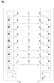
- Figure 1 shows an embodiment of the inventive light barrier arrangement of a light curtain 1 for detecting objects in a surveillance area.
- the light curtain 1 has a first housing 2 in which a number of transmitters 401, 402, 403, 404, 405, 406, 407, 408 emitting light beams 3 are arranged. In the present case, eight transmitters 401, 402, 403, 404, 405, 406, 407, 408 are provided. Of course, the light curtain 1 can also have a different number of transmitters 401, 402, 403, 404, 405, 406, 407, 408.
- the preferably identically designed transmitters 401, 402, 403, 404, 405, 406, 407, 408 are formed by light-emitting diodes that emit light in the visible or invisible range, in particular the infrared range.
- All transmitters 401, 402, 403, 404, 405, 406, 407, 408 are arranged in a linear arrangement on a circuit board 5.
- Each transmitter 401, 402, 403, 404, 405, 406, 407, 408 has a transmitting optics 6 in the form of a lens arranged in front of it for beam shaping of its light beams 3.
- a common transmitting optics 6 can be provided for several transmitters 401, 402, 403, 404, 405, 406, 407, 408.
- the operation of the transmitters 401, 402, 403, 404, 405, 406, 407, 408 is controlled by a transmitter control 7.
- the light curtain 1 further comprises a second housing 8 in which a number of receivers 10 are provided on a further circuit board 9.
- the number of receivers 10 corresponds to the number of transmitters 401, 402, 403, 404, 405, 406, 407, 408.
- the receivers 10, which are identical in the present case, are formed by photodiodes.
- Each receiver 10 is provided with a receiving optics 11 The received signals at the output of the receiver 10 are evaluated in an evaluation unit 12.
- the light curtain 1 is designed as a safety sensor and has a fail-safe structure.
- the evaluation unit 12 has a redundant two-channel structure in the form of two computer units that cyclically monitor each other.
- the two housings 2, 8 of the light curtain 1 are arranged at opposite edges of the monitoring area so that when the monitoring area is free (as in Figure 1 shown) the light beams 3 of each transmitter 401, 402, 403, 404, 405, 406, 407, 408 strike the associated receiver 10 unhindered.
- the transmitter-receiver pairs formed in this way form beam axes of the light curtain 1, with which the monitoring area is monitored.
- An object intrusion into the monitoring area is detected by the light beams 3 of at least one beam axis being at least partially interrupted.
- a threshold value evaluation of the amplitudes of the received signals of the receivers 10 is carried out in the evaluation unit 12.
- a binary object detection signal is generated in the evaluation unit 12, the switching states of which indicate whether an object is in the monitoring area or not.
- the light barrier arrangement can also consist of a number of individual light barriers whose transmitters 401, 402, 403, 404, 405, 406, 407, 408 are jointly controlled and whose receivers 10 generate received signals which are jointly evaluated.
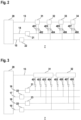
- FIG. 2 shows a first embodiment of the transmitter control 7 according to the invention.
- the transmitter control 7 comprises a control module 20 and control elements 31, 32, 33, 34 and control elements 21, 22 connected to it via control lines 13, 14, 15.
- the control module 20 consists of a microprocessor or the like, the control elements 31, 32, 33, 34 and the control elements 21, 22 advantageously consist of individual switching elements, in particular transistors.
- control elements 31, 32, 33, 34 are provided.
- a control line 13 is looped through from the control module 20 to all control elements 31, 32, 33, 34, so that the control elements 31, 32, 33, 34 form a series circuit connected to the control module 20.
- the control elements 21, 22 are connected in parallel to the control module 20 via control lines 14, 15.
- the control lines 13, 14, 15 can be designed as modulation lines.
- shift register elements can be provided for controlling the control elements 31, 32, 33, 34 or control elements 21, 22.
- the control module 20 controls the control elements 21, 22 and the control elements 31, 32, 33, 34, whereby the timing of the activation of the transmitters 401, 402, 403, 404, 405, 406, 407, 408 can be specified.
- a group of two transmitters 401, 402 and 403, 404 and 405, 406 and 407, 408 is connected to each control element 31, 32, 33, 34, so that each control element 31, 32, 33, 34 controls such a group of transmitters 401, 402 and 403, 404 and 405, 406 and 407, 408.
- control elements 21, 22 are provided, which are controlled via the control module 20.
- One control element 21, 22 is connected to only the first transmitter 401, 403, 405, 407 of all groups.
- the second control element 21, 22 is connected to the second transmitter 402, 404, 406, 408 of all groups.
- control elements 21, 22 and control elements 31, 32, 33, 34 form a matrix-shaped control circuit for the transmitters 401, 402, 403, 404, 405, 406, 407, 408, wherein each transmitter 401, 402, 403, 404, 405, 406, 407, 408 is connected to a specific, individual combination of only one drive element 31, 32, 33, 34 and only one control element 21, 22.
- a transmitter 401, 402, 403, 404, 405, 406, 407, 408 is only activated and emits light beams 3 when it is correspondingly controlled by the control element 31, 32, 33, 34 and the control element 21, 22 to which it is connected.
- the control elements 31, 32, 33, 34 and control elements 21, 22 can be used to flexibly control the timing of the activations of the individual transmitters 401, 402, 403, 404, 405, 406, 407, 408.
- the transmitters 401, 402, 403, 404, 405, 406, 407, 408 can be activated cyclically one after the other, individually or in groups.
- the transmitter control 7 can be varied such that N (where N > 2) transmitters 401, 402, 403, 404, 405, 406, 407, 408 are connected to each control element 31, 32, 33, 34 and form a group of transmitters 401, 402, 403, 404, 405, 406, 407, 408. Then N control elements are provided, to each of which a transmitter of each group is connected.
- FIG. 3 A corresponding embodiment shows Figure 3 .
- This transmitter control 7 has two control elements 31, 32, which are connected to the control module 20 via the control line 13.
- a group of four transmitters 401, 402, 403, 404 and 405, 406, 407, 408 is connected to each control element 31, 32.
- four control elements 21, 22, 23, 24 are assigned to these groups, each of which is connected to the control module 20 via a control line 16, 17, 18, 19.
- Each control element 21, 22, 23, 24 is connected to exactly one transmitter 401, 402, 403, 404, 405, 406, 407, 408 of each group.
- the individual control elements 21, 22, 23, 24 are connected to different transmitters 401, 402, 403, 404, 405, 406, 407, 408, so that with the control elements 21, 22, 23, 24 and control elements 31,32 again a matrix-shaped Arrangement of the transmitters 401, 402, 403, 404, 405, 406, 407, 408 is obtained such that each transmitter 401, 402, 403, 404, 405, 406, 407, 408 is controlled by an individual combination of exactly one control element 31, 32 and exactly one control element 21, 22, 23, 24.
- the functioning of the transmitter control 7 according to Figure 3 is analogous to the transmitter control 7 according to Figure 2 .
Landscapes
- Physics & Mathematics (AREA)
- Life Sciences & Earth Sciences (AREA)
- General Life Sciences & Earth Sciences (AREA)
- General Physics & Mathematics (AREA)
- Geophysics (AREA)
- Burglar Alarm Systems (AREA)
- Optical Communication System (AREA)
- Geophysics And Detection Of Objects (AREA)
Claims (12)
- Système de barrière lumineuse pour la détection d'objets dans une zone de surveillance avec un arrangement d'émetteurs (401, 402, 403, 404, 405, 406, 407, 408) émettant des faisceaux lumineux (3) et un certain nombre de récepteurs (10) affectés aux émetteurs (401, 402, 403, 404, 405, 406, 407, 408), avec une commande d'émetteur (7) permettant de commander le fonctionnement des émetteurs (401, 402, 405, 407, 408), avec une commande d'émetteur (7) permettant de commander le fonctionnement des émetteurs (401, 402, 403, 404, 405, 405, 406, 407, 408), avec une commande d'émetteur (7), avec laquelle le fonctionnement des émetteurs (401, 402, 403, 404, 405, 406, 407, 408) est commandé, dans laquelle la commande d'émetteur (7) a un certain nombre d'éléments de commande (31, 32, 33, 34), dans lequel chaque élément de commande (31, 32, 33, 34) commande un groupe d'émetteurs (401, 402 et 403, 404 et 405, 406 et 407, 408), et avec un certain nombre d'éléments de commande (21, 22, 23, 24), dans lequel chaque élément de commande (21, 22, 23, 24) commande un seul émetteur (401, 402, 403, 404, 405, 406, 407, 408), et avec un certain nombre d'éléments de commande (21, 22, 23, 24), dans lequel chaque élément de commande (21, 22, 23, 24) commande un seul émetteur (401, 402, 403, 404, 405, 406, 407, 408) d'un groupe, dans lequel un émetteur (401, 402, 403, 404, 405, 406, 407, 408) n'émet des faisceaux lumineux (3) que lorsqu'il est activé par l'élément de commande (31, 32, 33, 34) qui lui est affecté et par l'élément de commande (21, 22, 23, 24) qui lui est affecté, les éléments de commande (31, 32, 33, 34) étant disposés à de petites distances les uns des autres, et les émetteurs (401, 402, 403, 404, 405, 406, 407, 408) à de petites distances les uns des autres. 33, 34) sont disposés à faible distance des émetteurs (401, 402, 403, 404, 405, 406, 407, 408) qui leur sont respectivement attribués, et les éléments de commande (21, 22, 23, 24) sont disposés à grande distance des émetteurs (401, 402, 403, 404, 405, 406, 407, 408) des différents groupes, les émetteurs (401, 402, 403, 404, 405, 406, 407, 408) sont disposés sur une carte de circuit imprimé et les éléments de commande (31, 32, 33, 34) avec les émetteurs (401, 402, 403, 404, 405, 406, 407, 408) sont disposés sur la carte de circuit imprimé ou les émetteurs d'un groupe et l'élément de commande associé (31, 32, 33, 34) sont chacun disposés sur une carte de circuit imprimé, tandis que les éléments de commande (21, 22, 23, 24) sont disposés dans l'espace à partir de celle-ci.
- Système de barrière lumineuse selon la revendication 1, caractérisé en ce que plusieurs éléments d'actionnement identiques (31, 32, 33, 34) sont prévus, le même nombre d'émetteurs (401, 402, 403, 404, 405, 406, 407, 408) étant attribué en tant que groupe à tous les éléments d'actionnement (31, 32, 33, 34).
- Système de barrière lumineuse selon l'une des revendications 1 ou 2, caractérisé en ce que chaque élément de commande (21, 22, 23, 24) commande un émetteur respectif (401, 402, 403, 404, 405, 406, 407, 408) dans tous les groupes.
- Système de barrière lumineuse selon la revendication 3, caractérisé en ce que le nombre d'éléments de commande (21, 22, 23, 24) correspond au nombre d'émetteurs (401, 402, 403, 404, 405, 406, 407, 408) d'un groupe affecté à un élément de commande (31, 32, 33, 34).
- Barrière lumineuse selon l'une des revendications 1 à 4, caractérisée en ce que la commande de l'émetteur (7) comporte un module de commande (20) qui permet de commander le fonctionnement des éléments d'actionnement (31, 32, 33, 34) et des éléments de commande (21, 22, 23, 24).
- Système de barrière lumineuse selon l'une des revendications 1 à 5, caractérisé en ce que des éléments de registre à décalage et/ou une ligne de modulation sont prévus pour actionner les éléments de commande (21, 22, 23, 24) et/ou les éléments d'actionnement (31, 32, 33, 34).
- Système de barrière lumineuse selon l'une des revendications 1 à 6, caractérisé en ce que chaque élément d'actionnement (31, 32, 33, 34) comporte un élément de commutation pour actionner le groupe respectif d'émetteurs (401, 402, 403, 404, 405, 406, 407, 408).
- Système de barrière lumineuse selon l'une des revendications 1 à 7, caractérisé en ce que chaque élément de commande (21, 22, 23, 24) possède un élément de commutation pour activer un émetteur respectif (401, 402, 403, 404, 405, 406, 407, 408) de son groupe.
- Système de barrière lumineuse selon l'une des revendications 1 à 8, caractérisé en ce que les émetteurs (401, 402, 403, 404, 405, 406, 407, 408) sont constitués de diodes électroluminescentes qui émettent des faisceaux lumineux (3) dans la gamme des longueurs d'onde visibles ou invisibles.
- Système de barrière lumineuse selon l'une des revendications 1 à 9, caractérisé en ce que chaque émetteur (401, 402, 403, 404, 405, 406, 407, 408) est associé à un émetteur optique (6), où chaque émetteur (401, 402, 403, 404, 405, 406, 407, 408) se voit attribuer un système optique de transmission séparé (6), ou en ce qu'une pluralité d'émetteurs (401, 402, 403, 404, 405, 406, 407, 408) sont combinés pour former des modules auxquels est attribué un système optique de transmission commun (6).
- Système de barrière lumineuse selon l'une des revendications 1 à 10, caractérisé en ce qu'il est conçu comme rideau lumineux (1).
- Système de barrière lumineuse selon l'une des revendications 1 à 11, caractérisé en ce qu'il est conçu comme un capteur de sécurité.
Applications Claiming Priority (1)
| Application Number | Priority Date | Filing Date | Title |
|---|---|---|---|
| DE202018105747.2U DE202018105747U1 (de) | 2018-10-08 | 2018-10-08 | Lichtschrankenanordnung |
Publications (2)
| Publication Number | Publication Date |
|---|---|
| EP3637155A1 EP3637155A1 (fr) | 2020-04-15 |
| EP3637155B1 true EP3637155B1 (fr) | 2025-01-01 |
Family
ID=67614420
Family Applications (1)
| Application Number | Title | Priority Date | Filing Date |
|---|---|---|---|
| EP19190638.7A Active EP3637155B1 (fr) | 2018-10-08 | 2019-08-08 | Système de barrière lumineuse |
Country Status (2)
| Country | Link |
|---|---|
| EP (1) | EP3637155B1 (fr) |
| DE (1) | DE202018105747U1 (fr) |
Citations (1)
| Publication number | Priority date | Publication date | Assignee | Title |
|---|---|---|---|---|
| US5635724A (en) * | 1995-06-07 | 1997-06-03 | Intecolor | Method and apparatus for detecting the location of an object on a surface |
Family Cites Families (7)
| Publication number | Priority date | Publication date | Assignee | Title |
|---|---|---|---|---|
| DE4033234A1 (de) * | 1990-10-19 | 1992-04-23 | Datalogic Optic Electronics Pr | Sicherheitslichtgitter |
| US5220177A (en) * | 1991-06-24 | 1993-06-15 | Harris Instrument Corporation | Method and apparatus for edge detection and location |
| US5347135A (en) * | 1991-06-24 | 1994-09-13 | Harris Instrument Corporation | Method and apparatus employing a linear array IR region radiation devices for locating the position of conveyor transported products |
| JP3788502B2 (ja) * | 2000-08-11 | 2006-06-21 | オムロン株式会社 | 光カーテン創成装置 |
| DE10212432A1 (de) * | 2002-03-21 | 2003-10-16 | Leuze Electronic Gmbh & Co | Optischer Sensor |
| JP2004328545A (ja) * | 2003-04-25 | 2004-11-18 | Sharp Corp | デコード回路ならびにそれを用いるディスク記録/再生装置の受光アンプ回路および光学ピックアップ |
| DE102005046478B4 (de) * | 2004-09-30 | 2019-03-14 | Omron Corp. | Photoelektrischer Mehrstrahl-Sensor |
-
2018
- 2018-10-08 DE DE202018105747.2U patent/DE202018105747U1/de active Active
-
2019
- 2019-08-08 EP EP19190638.7A patent/EP3637155B1/fr active Active
Patent Citations (1)
| Publication number | Priority date | Publication date | Assignee | Title |
|---|---|---|---|---|
| US5635724A (en) * | 1995-06-07 | 1997-06-03 | Intecolor | Method and apparatus for detecting the location of an object on a surface |
Also Published As
| Publication number | Publication date |
|---|---|
| DE202018105747U1 (de) | 2020-01-09 |
| EP3637155A1 (fr) | 2020-04-15 |
Similar Documents
| Publication | Publication Date | Title |
|---|---|---|
| EP2147338B1 (fr) | Détecteur optoélectronique permettant de sécuriser une zone dangereuse | |
| EP1933174B1 (fr) | Barrière lumineuse | |
| DE102012101369B4 (de) | Lichtvorhang | |
| DE102012101368B4 (de) | Lichtvorhang | |
| EP2071363B1 (fr) | Barrière lumineuse et son procédé de fonctionnement | |
| EP3822666B1 (fr) | Agencement de barrières lumineuses | |
| DE102012101431B4 (de) | Sensoranordnung | |
| DE102013106785B4 (de) | Verfahren zur Synchronisation eines Lichtgitters und auf diesem Verfahren beruhendes Lichtgitter | |
| DE102007043378B4 (de) | Lichtgitter | |
| DE102018117878B4 (de) | Sicherheitslichtgitter | |
| DE102005050979B4 (de) | Verfahren zur Funktionsüberprüfung einer Sicherheitsausgangsschaltung eines optischen Sensors | |
| EP2502098B1 (fr) | Rideau photoélectrique | |
| EP2672296B1 (fr) | Rideau lumineux | |
| EP3637155B1 (fr) | Système de barrière lumineuse | |
| DE202007007290U1 (de) | Optoelektronische Sensoranordnung | |
| DE10120940B4 (de) | Sicherheitseinrichtung zur Überwachung von mindestens zwei aneinandergrenzenden Ebenen durch Lichtschrankenanordnungen, insbesondere Lichtvorhänge | |
| DE102008022791B4 (de) | Lichtvorhang | |
| EP4092449B1 (fr) | Agencement de barrière lumineuse et procédé de détection des objets dans une zone de surveillance | |
| EP2259093B1 (fr) | Dispositif de capteur optoélectronique et procédé de fonctionnement d'un tel dispositif | |
| DE202018104258U1 (de) | Sicherheitslichtgitter | |
| DE19861128B4 (de) | Optischer Türwächter | |
| EP1480060B1 (fr) | Capteur optique | |
| EP4279792B1 (fr) | Rideau lumineux | |
| EP4411426B1 (fr) | Rideau lumineux | |
| EP3770647A1 (fr) | Agencement de barrière lumineuse et procédé d'ajustement d'un agencement de barrière lumineuse |
Legal Events
| Date | Code | Title | Description |
|---|---|---|---|
| PUAI | Public reference made under article 153(3) epc to a published international application that has entered the european phase |
Free format text: ORIGINAL CODE: 0009012 |
|
| STAA | Information on the status of an ep patent application or granted ep patent |
Free format text: STATUS: THE APPLICATION HAS BEEN PUBLISHED |
|
| AK | Designated contracting states |
Kind code of ref document: A1 Designated state(s): AL AT BE BG CH CY CZ DE DK EE ES FI FR GB GR HR HU IE IS IT LI LT LU LV MC MK MT NL NO PL PT RO RS SE SI SK SM TR |
|
| AX | Request for extension of the european patent |
Extension state: BA ME |
|
| STAA | Information on the status of an ep patent application or granted ep patent |
Free format text: STATUS: REQUEST FOR EXAMINATION WAS MADE |
|
| 17P | Request for examination filed |
Effective date: 20200415 |
|
| RBV | Designated contracting states (corrected) |
Designated state(s): AL AT BE BG CH CY CZ DE DK EE ES FI FR GB GR HR HU IE IS IT LI LT LU LV MC MK MT NL NO PL PT RO RS SE SI SK SM TR |
|
| STAA | Information on the status of an ep patent application or granted ep patent |
Free format text: STATUS: EXAMINATION IS IN PROGRESS |
|
| 17Q | First examination report despatched |
Effective date: 20220627 |
|
| P01 | Opt-out of the competence of the unified patent court (upc) registered |
Effective date: 20240423 |
|
| GRAP | Despatch of communication of intention to grant a patent |
Free format text: ORIGINAL CODE: EPIDOSNIGR1 |
|
| STAA | Information on the status of an ep patent application or granted ep patent |
Free format text: STATUS: GRANT OF PATENT IS INTENDED |
|
| GRAS | Grant fee paid |
Free format text: ORIGINAL CODE: EPIDOSNIGR3 |
|
| INTG | Intention to grant announced |
Effective date: 20241024 |
|
| GRAA | (expected) grant |
Free format text: ORIGINAL CODE: 0009210 |
|
| STAA | Information on the status of an ep patent application or granted ep patent |
Free format text: STATUS: THE PATENT HAS BEEN GRANTED |
|
| AK | Designated contracting states |
Kind code of ref document: B1 Designated state(s): AL AT BE BG CH CY CZ DE DK EE ES FI FR GB GR HR HU IE IS IT LI LT LU LV MC MK MT NL NO PL PT RO RS SE SI SK SM TR |
|
| REG | Reference to a national code |
Ref country code: GB Ref legal event code: FG4D Free format text: NOT ENGLISH |
|
| REG | Reference to a national code |
Ref country code: CH Ref legal event code: EP |
|
| REG | Reference to a national code |
Ref country code: DE Ref legal event code: R096 Ref document number: 502019012722 Country of ref document: DE |
|
| REG | Reference to a national code |
Ref country code: IE Ref legal event code: FG4D Free format text: LANGUAGE OF EP DOCUMENT: GERMAN |
|
| REG | Reference to a national code |
Ref country code: LT Ref legal event code: MG9D |
|
| REG | Reference to a national code |
Ref country code: NL Ref legal event code: MP Effective date: 20250101 |
|
| PG25 | Lapsed in a contracting state [announced via postgrant information from national office to epo] |
Ref country code: NL Free format text: LAPSE BECAUSE OF FAILURE TO SUBMIT A TRANSLATION OF THE DESCRIPTION OR TO PAY THE FEE WITHIN THE PRESCRIBED TIME-LIMIT Effective date: 20250101 |
|
| PG25 | Lapsed in a contracting state [announced via postgrant information from national office to epo] |
Ref country code: FI Free format text: LAPSE BECAUSE OF FAILURE TO SUBMIT A TRANSLATION OF THE DESCRIPTION OR TO PAY THE FEE WITHIN THE PRESCRIBED TIME-LIMIT Effective date: 20250101 |
|
| PG25 | Lapsed in a contracting state [announced via postgrant information from national office to epo] |
Ref country code: PL Free format text: LAPSE BECAUSE OF FAILURE TO SUBMIT A TRANSLATION OF THE DESCRIPTION OR TO PAY THE FEE WITHIN THE PRESCRIBED TIME-LIMIT Effective date: 20250101 |
|
| PG25 | Lapsed in a contracting state [announced via postgrant information from national office to epo] |
Ref country code: ES Free format text: LAPSE BECAUSE OF FAILURE TO SUBMIT A TRANSLATION OF THE DESCRIPTION OR TO PAY THE FEE WITHIN THE PRESCRIBED TIME-LIMIT Effective date: 20250101 |
|
| PG25 | Lapsed in a contracting state [announced via postgrant information from national office to epo] |
Ref country code: IS Free format text: LAPSE BECAUSE OF FAILURE TO SUBMIT A TRANSLATION OF THE DESCRIPTION OR TO PAY THE FEE WITHIN THE PRESCRIBED TIME-LIMIT Effective date: 20250501 Ref country code: NO Free format text: LAPSE BECAUSE OF FAILURE TO SUBMIT A TRANSLATION OF THE DESCRIPTION OR TO PAY THE FEE WITHIN THE PRESCRIBED TIME-LIMIT Effective date: 20250401 |
|
| PG25 | Lapsed in a contracting state [announced via postgrant information from national office to epo] |
Ref country code: HR Free format text: LAPSE BECAUSE OF FAILURE TO SUBMIT A TRANSLATION OF THE DESCRIPTION OR TO PAY THE FEE WITHIN THE PRESCRIBED TIME-LIMIT Effective date: 20250101 |
|
| PG25 | Lapsed in a contracting state [announced via postgrant information from national office to epo] |
Ref country code: PT Free format text: LAPSE BECAUSE OF FAILURE TO SUBMIT A TRANSLATION OF THE DESCRIPTION OR TO PAY THE FEE WITHIN THE PRESCRIBED TIME-LIMIT Effective date: 20250502 Ref country code: LV Free format text: LAPSE BECAUSE OF FAILURE TO SUBMIT A TRANSLATION OF THE DESCRIPTION OR TO PAY THE FEE WITHIN THE PRESCRIBED TIME-LIMIT Effective date: 20250101 |
|
| PG25 | Lapsed in a contracting state [announced via postgrant information from national office to epo] |
Ref country code: BG Free format text: LAPSE BECAUSE OF FAILURE TO SUBMIT A TRANSLATION OF THE DESCRIPTION OR TO PAY THE FEE WITHIN THE PRESCRIBED TIME-LIMIT Effective date: 20250101 Ref country code: GR Free format text: LAPSE BECAUSE OF FAILURE TO SUBMIT A TRANSLATION OF THE DESCRIPTION OR TO PAY THE FEE WITHIN THE PRESCRIBED TIME-LIMIT Effective date: 20250402 |
|
| PG25 | Lapsed in a contracting state [announced via postgrant information from national office to epo] |
Ref country code: CZ Free format text: LAPSE BECAUSE OF FAILURE TO SUBMIT A TRANSLATION OF THE DESCRIPTION OR TO PAY THE FEE WITHIN THE PRESCRIBED TIME-LIMIT Effective date: 20250101 |
|
| PG25 | Lapsed in a contracting state [announced via postgrant information from national office to epo] |
Ref country code: SE Free format text: LAPSE BECAUSE OF FAILURE TO SUBMIT A TRANSLATION OF THE DESCRIPTION OR TO PAY THE FEE WITHIN THE PRESCRIBED TIME-LIMIT Effective date: 20250101 |
|
| REG | Reference to a national code |
Ref country code: DE Ref legal event code: R097 Ref document number: 502019012722 Country of ref document: DE |
|
| PG25 | Lapsed in a contracting state [announced via postgrant information from national office to epo] |
Ref country code: SM Free format text: LAPSE BECAUSE OF FAILURE TO SUBMIT A TRANSLATION OF THE DESCRIPTION OR TO PAY THE FEE WITHIN THE PRESCRIBED TIME-LIMIT Effective date: 20250101 |
|
| PG25 | Lapsed in a contracting state [announced via postgrant information from national office to epo] |
Ref country code: DK Free format text: LAPSE BECAUSE OF FAILURE TO SUBMIT A TRANSLATION OF THE DESCRIPTION OR TO PAY THE FEE WITHIN THE PRESCRIBED TIME-LIMIT Effective date: 20250101 |
|
| PGFP | Annual fee paid to national office [announced via postgrant information from national office to epo] |
Ref country code: DE Payment date: 20250820 Year of fee payment: 7 |
|
| PG25 | Lapsed in a contracting state [announced via postgrant information from national office to epo] |
Ref country code: IT Free format text: LAPSE BECAUSE OF FAILURE TO SUBMIT A TRANSLATION OF THE DESCRIPTION OR TO PAY THE FEE WITHIN THE PRESCRIBED TIME-LIMIT Effective date: 20250101 |
|
| PG25 | Lapsed in a contracting state [announced via postgrant information from national office to epo] |
Ref country code: EE Free format text: LAPSE BECAUSE OF FAILURE TO SUBMIT A TRANSLATION OF THE DESCRIPTION OR TO PAY THE FEE WITHIN THE PRESCRIBED TIME-LIMIT Effective date: 20250101 |
|
| PG25 | Lapsed in a contracting state [announced via postgrant information from national office to epo] |
Ref country code: RO Free format text: LAPSE BECAUSE OF FAILURE TO SUBMIT A TRANSLATION OF THE DESCRIPTION OR TO PAY THE FEE WITHIN THE PRESCRIBED TIME-LIMIT Effective date: 20250101 |
|
| PG25 | Lapsed in a contracting state [announced via postgrant information from national office to epo] |
Ref country code: SK Free format text: LAPSE BECAUSE OF FAILURE TO SUBMIT A TRANSLATION OF THE DESCRIPTION OR TO PAY THE FEE WITHIN THE PRESCRIBED TIME-LIMIT Effective date: 20250101 |
|
| PLBE | No opposition filed within time limit |
Free format text: ORIGINAL CODE: 0009261 |
|
| STAA | Information on the status of an ep patent application or granted ep patent |
Free format text: STATUS: NO OPPOSITION FILED WITHIN TIME LIMIT |
|
| REG | Reference to a national code |
Ref country code: CH Ref legal event code: L10 Free format text: ST27 STATUS EVENT CODE: U-0-0-L10-L00 (AS PROVIDED BY THE NATIONAL OFFICE) Effective date: 20251112 |
|
| 26N | No opposition filed |
Effective date: 20251002 |
|
| REG | Reference to a national code |
Ref country code: CH Ref legal event code: H13 Free format text: ST27 STATUS EVENT CODE: U-0-0-H10-H13 (AS PROVIDED BY THE NATIONAL OFFICE) Effective date: 20260324 |
|
| PG25 | Lapsed in a contracting state [announced via postgrant information from national office to epo] |
Ref country code: MC Free format text: LAPSE BECAUSE OF FAILURE TO SUBMIT A TRANSLATION OF THE DESCRIPTION OR TO PAY THE FEE WITHIN THE PRESCRIBED TIME-LIMIT Effective date: 20250101 |
|
| PG25 | Lapsed in a contracting state [announced via postgrant information from national office to epo] |
Ref country code: LU Free format text: LAPSE BECAUSE OF NON-PAYMENT OF DUE FEES Effective date: 20250808 |
|
| PG25 | Lapsed in a contracting state [announced via postgrant information from national office to epo] |
Ref country code: CH Free format text: LAPSE BECAUSE OF NON-PAYMENT OF DUE FEES Effective date: 20250831 |