EP2463746A2 - Système terminal destiné à l'application d'un terminal sur un treillis à barres verticales et au couplage électrique du terminal à un réseau ou une unité de traitement - Google Patents
Système terminal destiné à l'application d'un terminal sur un treillis à barres verticales et au couplage électrique du terminal à un réseau ou une unité de traitement Download PDFInfo
- Publication number
- EP2463746A2 EP2463746A2 EP11009607A EP11009607A EP2463746A2 EP 2463746 A2 EP2463746 A2 EP 2463746A2 EP 11009607 A EP11009607 A EP 11009607A EP 11009607 A EP11009607 A EP 11009607A EP 2463746 A2 EP2463746 A2 EP 2463746A2
- Authority
- EP
- European Patent Office
- Prior art keywords
- terminal
- adapter
- receptacle
- terminal system
- multipin connector
- Prior art date
- Legal status (The legal status is an assumption and is not a legal conclusion. Google has not performed a legal analysis and makes no representation as to the accuracy of the status listed.)
- Withdrawn
Links
Images


Classifications
-
- G—PHYSICS
- G06—COMPUTING OR CALCULATING; COUNTING
- G06F—ELECTRIC DIGITAL DATA PROCESSING
- G06F1/00—Details not covered by groups G06F3/00 - G06F13/00 and G06F21/00
- G06F1/16—Constructional details or arrangements
- G06F1/1601—Constructional details related to the housing of computer displays, e.g. of CRT monitors, of flat displays
-
- F—MECHANICAL ENGINEERING; LIGHTING; HEATING; WEAPONS; BLASTING
- F16—ENGINEERING ELEMENTS AND UNITS; GENERAL MEASURES FOR PRODUCING AND MAINTAINING EFFECTIVE FUNCTIONING OF MACHINES OR INSTALLATIONS; THERMAL INSULATION IN GENERAL
- F16M—FRAMES, CASINGS OR BEDS OF ENGINES, MACHINES OR APPARATUS, NOT SPECIFIC TO ENGINES, MACHINES OR APPARATUS PROVIDED FOR ELSEWHERE; STANDS; SUPPORTS
- F16M11/00—Stands or trestles as supports for apparatus or articles placed thereon ; Stands for scientific apparatus such as gravitational force meters
- F16M11/02—Heads
- F16M11/04—Means for attachment of apparatus; Means allowing adjustment of the apparatus relatively to the stand
- F16M11/041—Allowing quick release of the apparatus
-
- F—MECHANICAL ENGINEERING; LIGHTING; HEATING; WEAPONS; BLASTING
- F16—ENGINEERING ELEMENTS AND UNITS; GENERAL MEASURES FOR PRODUCING AND MAINTAINING EFFECTIVE FUNCTIONING OF MACHINES OR INSTALLATIONS; THERMAL INSULATION IN GENERAL
- F16M—FRAMES, CASINGS OR BEDS OF ENGINES, MACHINES OR APPARATUS, NOT SPECIFIC TO ENGINES, MACHINES OR APPARATUS PROVIDED FOR ELSEWHERE; STANDS; SUPPORTS
- F16M11/00—Stands or trestles as supports for apparatus or articles placed thereon ; Stands for scientific apparatus such as gravitational force meters
- F16M11/02—Heads
- F16M11/04—Means for attachment of apparatus; Means allowing adjustment of the apparatus relatively to the stand
- F16M11/06—Means for attachment of apparatus; Means allowing adjustment of the apparatus relatively to the stand allowing pivoting
- F16M11/10—Means for attachment of apparatus; Means allowing adjustment of the apparatus relatively to the stand allowing pivoting around a horizontal axis
-
- F—MECHANICAL ENGINEERING; LIGHTING; HEATING; WEAPONS; BLASTING
- F16—ENGINEERING ELEMENTS AND UNITS; GENERAL MEASURES FOR PRODUCING AND MAINTAINING EFFECTIVE FUNCTIONING OF MACHINES OR INSTALLATIONS; THERMAL INSULATION IN GENERAL
- F16M—FRAMES, CASINGS OR BEDS OF ENGINES, MACHINES OR APPARATUS, NOT SPECIFIC TO ENGINES, MACHINES OR APPARATUS PROVIDED FOR ELSEWHERE; STANDS; SUPPORTS
- F16M13/00—Other supports for positioning apparatus or articles; Means for steadying hand-held apparatus or articles
- F16M13/02—Other supports for positioning apparatus or articles; Means for steadying hand-held apparatus or articles for supporting on, or attaching to, an object, e.g. tree, gate, window-frame, cycle
-
- G—PHYSICS
- G06—COMPUTING OR CALCULATING; COUNTING
- G06F—ELECTRIC DIGITAL DATA PROCESSING
- G06F1/00—Details not covered by groups G06F3/00 - G06F13/00 and G06F21/00
- G06F1/16—Constructional details or arrangements
- G06F1/1613—Constructional details or arrangements for portable computers
- G06F1/1632—External expansion units, e.g. docking stations
-
- G—PHYSICS
- G06—COMPUTING OR CALCULATING; COUNTING
- G06F—ELECTRIC DIGITAL DATA PROCESSING
- G06F1/00—Details not covered by groups G06F3/00 - G06F13/00 and G06F21/00
- G06F1/16—Constructional details or arrangements
- G06F1/1613—Constructional details or arrangements for portable computers
- G06F1/1633—Constructional details or arrangements of portable computers not specific to the type of enclosures covered by groups G06F1/1615 - G06F1/1626
- G06F1/1656—Details related to functional adaptations of the enclosure, e.g. to provide protection against EMI, shock, water, or to host detachable peripherals like a mouse or removable expansions units like PCMCIA cards, or to provide access to internal components for maintenance or to removable storage supports like CDs or DVDs, or to mechanically mount accessories
-
- G—PHYSICS
- G06—COMPUTING OR CALCULATING; COUNTING
- G06F—ELECTRIC DIGITAL DATA PROCESSING
- G06F1/00—Details not covered by groups G06F3/00 - G06F13/00 and G06F21/00
- G06F1/16—Constructional details or arrangements
- G06F1/18—Packaging or power distribution
- G06F1/181—Enclosures
-
- G—PHYSICS
- G06—COMPUTING OR CALCULATING; COUNTING
- G06F—ELECTRIC DIGITAL DATA PROCESSING
- G06F21/00—Security arrangements for protecting computers, components thereof, programs or data against unauthorised activity
- G06F21/70—Protecting specific internal or peripheral components, in which the protection of a component leads to protection of the entire computer
- G06F21/88—Detecting or preventing theft or loss
-
- F—MECHANICAL ENGINEERING; LIGHTING; HEATING; WEAPONS; BLASTING
- F16—ENGINEERING ELEMENTS AND UNITS; GENERAL MEASURES FOR PRODUCING AND MAINTAINING EFFECTIVE FUNCTIONING OF MACHINES OR INSTALLATIONS; THERMAL INSULATION IN GENERAL
- F16M—FRAMES, CASINGS OR BEDS OF ENGINES, MACHINES OR APPARATUS, NOT SPECIFIC TO ENGINES, MACHINES OR APPARATUS PROVIDED FOR ELSEWHERE; STANDS; SUPPORTS
- F16M2200/00—Details of stands or supports
- F16M2200/02—Locking means
-
- F—MECHANICAL ENGINEERING; LIGHTING; HEATING; WEAPONS; BLASTING
- F16—ENGINEERING ELEMENTS AND UNITS; GENERAL MEASURES FOR PRODUCING AND MAINTAINING EFFECTIVE FUNCTIONING OF MACHINES OR INSTALLATIONS; THERMAL INSULATION IN GENERAL
- F16M—FRAMES, CASINGS OR BEDS OF ENGINES, MACHINES OR APPARATUS, NOT SPECIFIC TO ENGINES, MACHINES OR APPARATUS PROVIDED FOR ELSEWHERE; STANDS; SUPPORTS
- F16M2200/00—Details of stands or supports
- F16M2200/06—Arms
- F16M2200/065—Arms with a special structure, e.g. reinforced or adapted for space reduction
-
- G—PHYSICS
- G06—COMPUTING OR CALCULATING; COUNTING
- G06F—ELECTRIC DIGITAL DATA PROCESSING
- G06F2200/00—Indexing scheme relating to G06F1/04 - G06F1/32
- G06F2200/16—Indexing scheme relating to G06F1/16 - G06F1/18
- G06F2200/163—Indexing scheme relating to constructional details of the computer
- G06F2200/1639—Arrangements for locking plugged peripheral connectors
Definitions
- the invention relates to a terminal system for attaching a terminal to a stator and for electrically coupling the terminal to a network or a processing unit.
- Terminal systems are used, for example, as POS systems in wholesale and retail.
- a terminal for example a flat screen
- the terminal is electrically coupled to a network, a processing unit or the like.
- the flat screen can be designed as a touch screen, so that he not only display function, but also input function and can largely replace a keyboard.
- Other terminals which may be used in the terminal system according to the invention are computers, printers, keyboards etc. At least one supply line and / or at least one signal line must always be routed from the terminal to the processing unit or to a network.
- the terminal system according to the invention for attaching a terminal to a stand and for electrically coupling the terminal to a network or processing unit consists essentially of three components, namely the terminal, an adapter which is attached to the terminal, wherein at least one supply line and / or at least one signal line for the terminal are merged onto a multipin connector, such as a receptacle having a multipin connector corresponding to the multipin connector of the adapter.
- a multipin connector such as a receptacle having a multipin connector corresponding to the multipin connector of the adapter.
- the terminal system according to the invention is extremely service-friendly.
- the installation of terminal and adapter is namely in advance and does not take place in the workplace to which the terminal system belongs. This means in particular that all electrical lines are connected correctly.
- the service staff must only release the lock against unauthorized access and remove the terminal located there with the adapter. Then the new terminal together with the attached adapter is simply put back into the receptacle so that the multipin connector of the adapter sits on the multipin connector of the receptacle. Subsequently, it can be locked again against unauthorized access.
- the workstation with the terminal system should usually be usable again after a few minutes. In addition, the replacement can be done by unskilled workers, such as courier drivers.
- the lock is done against unauthorized access by a mechanical or electrical lock.
- a mechanical or electrical lock may be thought to release the lock by entering a code.
- a uniform mechanical lock which is identical for example for all terminal systems of a company, is particularly simple. The key can then be stored in a secure location and is immediately available if needed.
- the adapter has a guide aid for the receptacle to suitably bring the multipin connector of the adapter into electrical contact with the multipin connector of the receptacle.
- a guide aid for the receptacle to suitably bring the multipin connector of the adapter into electrical contact with the multipin connector of the receptacle.
- the guide aid may comprise at least one groove of predefined length, into which a complementary guide rail of the receptacle is to be inserted.
- the groove has a closed end and an open end, the open end being flared in a funnel shape to facilitate insertion of the guide rail (s).
- the groove is undercut over its length.
- it may have a T-profile or a dovetail profile in cross-section. This contributes to the safety against tilting when inserting the adapter into the receptacle.
- the removal or insertion of the adapter happens controlled, it can be provided that in addition to the electrical or mechanical locking a latching lock is provided.
- the adapter and receptacle are latchingly engaged.
- the latching engagement takes place as soon as the guide rail (s) of the receptacle has reached its end position in the groove or the grooves of the adapter.
- the guide rail may have a recess into which a locking tab provided on the adapter releasably engages.
- This latching lock can be canceled, for example, by appropriate release lever for the locking tab (s) again. If these release levers are arranged ergonomically favorable, it is ensured at the same time that the service operator carefully and controlled the terminal from the recording and uses in this.
- a further mounting system such as a pipe is attached to the receptacle, through which the outgoing from the multipin connector lines are led out as a cable from the receptacle.
- the tube can then open usual manner, for example, via a pivot connector to be mounted on a stud.
- the terminal system according to the invention also offers a completely different possibility, namely that the terminal can be used as a mobile device. This is useful, for example, when a long queue has formed at a cash register. An employee can then dissolve this queue by already receiving the goods in the terminal. Thanks to the universal adapter can then be used for billing any other cashier, then the mobile terminal is used in the appropriate recording.
- a scale requires a load cell, a customer scanner a bar code reader.
- the terminal system now makes it possible to exchange the base electronics by using the universal adapter in the corresponding environment. For example, if docked to a load cell with printer, a balance is made ready for operation, for example, for the fruit and vegetable department. If a docking station is coupled with a barcode reader, a price information terminal is available. In conjunction with a check-out table, the POS system already described is generated.
- customer behavior can also be taken into account.
- Customer behavior in a supermarket varies at different times. On Saturdays, customers usually want to make quick purchases. On other days, the shopping experience is in the foreground.
- the terminal system according to the present invention can also be easily remedied here, for example, the terminal of a price information terminal, as already described above, is used in strong customer traffic as an additional cash.
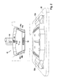
- FIG. 1 shows in a perspective view from above a terminal 10, for example a flat screen, which is supplied via a supply line 12 with energy, wherein data, in this case via the signal lines 14, 16, 18, can be transported. Not all signal lines need to be used, some signal lines may be kept free for other terminals such as a printer. This ensures the universality of the terminal system according to the invention. It is also conceivable that a combined supply and signal line is used. It is essential that the supply line and / or the signal lines are part of an adapter 20 which is constructed from an adapter body 22 and a guide block 24 mounted thereon. In the adapter body 22, the supply line 12 and the signal lines 14, 16, 18 are guided on a multipin connector 26.
- the guide block 24 is substantially parallelepiped-shaped and has grooves 30a, 30b on two opposite sides. These grooves 30a, 30b extend almost completely over the entire length of the sides. They are flared at their open end adjacent the multipin connector 26 to facilitate the insertion of guide rails, which will be described hereinafter. The opposite ends of the grooves 30a, 30b are closed, so that a certain end position is defined for the guide rails.
- the guide rails can be latched, wherein the latching engagement by release levers 32a, 32b, which are pivotable about an axis 34a, 34b and are biased in the position of the latching engagement, are canceled again.
- FIG. 2 shows the terminal 10 with the adapter 20 from FIG. 1 Before insertion into a receptacle 40.
- a pipe 60 with a pivoting element 62 is already mounted on the receptacle in preparation for attachment to a stud.
- the receptacle 40 consists of a receiving body 42, projecting from the two guide rails 44a, 44b, which have a T-shaped cross-section.
- the guide rails 44a and 44b are spaced according to the guide grooves 30a, 30b in the guide block 24 of the adapter 20. Since the receptacle 40 is finally attached to a stand, this is stationary.
- the guide rails 44a and 44b are substantially perpendicular, so that the adapter 20 is brought to the terminal 10 practically “from above” to the receptacle 40, that the guide rails 44a, 44b in the grooves 30a, 30b can grab it like that is shown by the dashed arrows.
- the adapter 20 with the terminal 10 is then lowered until the multipin connector of the adapter 20 - not visible in this drawing - sits on the multipin connector 52 of the receptacle 40. In this position, a locking connection audibly engages.
- the guide rails 44a, 44b by means of two locking tabs (not shown), which protrude into corresponding recesses 46a, 46b on the guide rails 44a, 44b, locked.
- a release lever 32a, 32b By means of a release lever 32a, 32b, the locking engagement can be canceled again.
- only one release lever 32 would be required - the guiding and contact function is maintained even if the second guide rail 44b would not be locked in the groove 30b - it is advantageous for ergonomic reasons to lock symmetrically and also provide two release levers 32a and 32b ,
- the adapter 20 with the terminal 10 can then be secured by means of the lock 50 against unauthorized access.
- FIG. 3 shows the set in the receptacle 40 adapter 20 attached thereto terminal 10.
- Adapter 20 and receptacle 40 are locked by means of a lock 50.
- the release levers 32a, 32b can be operated, but they show no effect, since the lock 50 secures the adapter 20 against pushing out.
- the outgoing from the multipin connector in the receptacle 40 lines are combined into a cable 66 which is passed through the tube 60. As a result, the so-called "cable salad" is completely avoided.
- the cable 66 is brought in through the stud frame or tube 60 during the first assembly, then the tube 60 is attached to the receptacle 40 and the leads of the cable 66 are routed to their proper ports on the multipin connector.
- a tube 60 which leads from the receptacle 40 to the framework, quite short and ends at the pivot member 62, so that the angular position of the terminal system according to the invention can be optimized with respect to the user. With the help of adjusting screws, the position is then fixed.
- FIG. 5 shows the connection to the actual stud 64, wherein a connecting tube is simply inserted into the pivoting element 62.
- the length of the cable 66 disappears in the stator 64th
Landscapes
- Engineering & Computer Science (AREA)
- General Engineering & Computer Science (AREA)
- Theoretical Computer Science (AREA)
- Computer Hardware Design (AREA)
- Physics & Mathematics (AREA)
- General Physics & Mathematics (AREA)
- Human Computer Interaction (AREA)
- Mechanical Engineering (AREA)
- Computer Security & Cryptography (AREA)
- Software Systems (AREA)
- Power Engineering (AREA)
- Details Of Connecting Devices For Male And Female Coupling (AREA)
Applications Claiming Priority (1)
| Application Number | Priority Date | Filing Date | Title |
|---|---|---|---|
| DE201010054156 DE102010054156B4 (de) | 2010-12-10 | 2010-12-10 | Terminalsystem zum Anbringen eines Endgerätes an einem Ständerwerk und zum elektrischen Koppeln des Endgerätes an ein Netzwerk oder eine Verarbeitungseinheit |
Publications (2)
| Publication Number | Publication Date |
|---|---|
| EP2463746A2 true EP2463746A2 (fr) | 2012-06-13 |
| EP2463746A3 EP2463746A3 (fr) | 2015-04-01 |
Family
ID=45495569
Family Applications (1)
| Application Number | Title | Priority Date | Filing Date |
|---|---|---|---|
| EP11009607.0A Withdrawn EP2463746A3 (fr) | 2010-12-10 | 2011-12-06 | Système terminal destiné à l'application d'un terminal sur un treillis à barres verticales et au couplage électrique du terminal à un réseau ou une unité de traitement |
Country Status (2)
| Country | Link |
|---|---|
| EP (1) | EP2463746A3 (fr) |
| DE (1) | DE102010054156B4 (fr) |
Cited By (4)
| Publication number | Priority date | Publication date | Assignee | Title |
|---|---|---|---|---|
| CN103921944A (zh) * | 2013-01-15 | 2014-07-16 | 松下航空电子公司 | 用于安装显示装置的组件和方法 |
| CN105632043A (zh) * | 2014-11-28 | 2016-06-01 | 南京亚士德科技有限公司 | Pos机 |
| DE102017103912A1 (de) | 2017-02-24 | 2018-08-30 | Harting Systems Gmbh | IT-Steckplatz für ein Kassensystem |
| EP3409996A1 (fr) * | 2017-06-01 | 2018-12-05 | Ingenico Group | Adaptateur pour la fixation d'un terminal de paiement electronique sur un support |
Citations (1)
| Publication number | Priority date | Publication date | Assignee | Title |
|---|---|---|---|---|
| GB2407925A (en) * | 2003-11-10 | 2005-05-11 | Tatung Co Ltd | A portable computer and a docking station |
Family Cites Families (9)
| Publication number | Priority date | Publication date | Assignee | Title |
|---|---|---|---|---|
| US5569895A (en) * | 1993-05-27 | 1996-10-29 | International Business Machines Corporation | I/O assembly for use with point of sale terminals and other computing systems |
| TW325174U (en) * | 1997-07-23 | 1998-01-11 | Jiung-Jung Wang | Simple retaining structure of display for use in cash register |
| WO2001015285A1 (fr) * | 1999-08-23 | 2001-03-01 | Mass Engineered Design | Appareil de connexion rapide universelle pour un moniteur acl |
| US6400560B1 (en) * | 2000-11-08 | 2002-06-04 | Yue-Hui Chian | Engaging device for a computer screen in a car |
| US6935883B2 (en) * | 2002-04-24 | 2005-08-30 | Innovative Office Products, Inc. | Quick interconnection system for electronic devices |
| CN2609080Y (zh) * | 2003-03-22 | 2004-03-31 | 汕头市川田科技有限公司 | 一种收款机 |
| US7453686B2 (en) * | 2005-08-29 | 2008-11-18 | Elbex Video Limited | Method and apparatus for attaching display panels onto wall surface |
| US7502226B2 (en) * | 2005-10-31 | 2009-03-10 | Hewlett-Packard Development Company, L.P. | Electronic device quick connect system |
| EP2110595A1 (fr) * | 2008-04-14 | 2009-10-21 | Hypercom GmbH | Support de terminal doté d'une articulation pivotante |
-
2010
- 2010-12-10 DE DE201010054156 patent/DE102010054156B4/de not_active Expired - Fee Related
-
2011
- 2011-12-06 EP EP11009607.0A patent/EP2463746A3/fr not_active Withdrawn
Patent Citations (1)
| Publication number | Priority date | Publication date | Assignee | Title |
|---|---|---|---|---|
| GB2407925A (en) * | 2003-11-10 | 2005-05-11 | Tatung Co Ltd | A portable computer and a docking station |
Non-Patent Citations (1)
| Title |
|---|
| BLAUPUNKT ET AL: "Radio CD MP3 WMA San Remo MP28, Bedienungs- und Einbauanleitung", 31 January 2008 (2008-01-31), pages 1 - 39, XP055270442, Retrieved from the Internet <URL:http://www.blaupunkt.com/fileadmin/user_upload/Service/SERVICEDOKU_ZIEL/EA/DE/7648493110001_EA_DE.pdf> [retrieved on 20160503] * |
Cited By (11)
| Publication number | Priority date | Publication date | Assignee | Title |
|---|---|---|---|---|
| CN103921944A (zh) * | 2013-01-15 | 2014-07-16 | 松下航空电子公司 | 用于安装显示装置的组件和方法 |
| EP2754610A3 (fr) * | 2013-01-15 | 2014-10-29 | Panasonic Avionics Corporation | Ensemble et procédé de montage de dispositif d'affichage |
| US9360895B2 (en) | 2013-01-15 | 2016-06-07 | Panasonic Avionics Corporation | Assembly and method for display device mounting |
| CN103921944B (zh) * | 2013-01-15 | 2017-07-18 | 松下航空电子公司 | 用于安装显示装置的组件和方法 |
| CN105632043A (zh) * | 2014-11-28 | 2016-06-01 | 南京亚士德科技有限公司 | Pos机 |
| CN105632043B (zh) * | 2014-11-28 | 2018-04-03 | 南京亚士德科技有限公司 | Pos机 |
| DE102017103912A1 (de) | 2017-02-24 | 2018-08-30 | Harting Systems Gmbh | IT-Steckplatz für ein Kassensystem |
| EP3409996A1 (fr) * | 2017-06-01 | 2018-12-05 | Ingenico Group | Adaptateur pour la fixation d'un terminal de paiement electronique sur un support |
| US20180350200A1 (en) * | 2017-06-01 | 2018-12-06 | Ingenico Group | Adaptor for affixing an electronic payment terminal to a support |
| FR3067091A1 (fr) * | 2017-06-01 | 2018-12-07 | Ingenico Group | Adaptateur pour la fixation d'un terminal de paiement electronique sur un support |
| US10332361B2 (en) | 2017-06-01 | 2019-06-25 | Ingenico Group | Adaptor for affixing an electronic payment terminal to a support |
Also Published As
| Publication number | Publication date |
|---|---|
| EP2463746A3 (fr) | 2015-04-01 |
| DE102010054156A1 (de) | 2012-06-14 |
| DE102010054156B4 (de) | 2013-08-29 |
Similar Documents
| Publication | Publication Date | Title |
|---|---|---|
| DE102008034704B3 (de) | Datenverarbeitungssystem | |
| EP2057718B1 (fr) | Systeme d'energie a rail | |
| DE102005043310A1 (de) | Anzeigesystem insbesondere für eine industrielle Automatisierungseinrichtung | |
| DE112011105952B4 (de) | Integration einer digitalen Mikrobeschilderungs-Hardware | |
| EP2463746A2 (fr) | Système terminal destiné à l'application d'un terminal sur un treillis à barres verticales et au couplage électrique du terminal à un réseau ou une unité de traitement | |
| DE102005012394A1 (de) | Höhenanpassbarer Ständer für einen LCD-Bildschirm mit Merkmalen zum Lösen und Einrasten in einer unteren Position | |
| WO1998039748A1 (fr) | Unite de commande modulaire pour le secteur commercial | |
| EP1358451A1 (fr) | Dispositif de pesee sans fil comprenant plusieurs unites fonctionnelles | |
| EP2237383A2 (fr) | Armoire avec barres omnibus enfichables | |
| DE112012005120B4 (de) | Anschlussmodule mit zwischen einer eingezogenen Position und einer ausgezogenen Position bewegbaren optischen Anschlüssen | |
| DE112019003107T5 (de) | Elektronisches Regalanzeigeetikett und stromführendes Regalträgerschienensystem sowie eine Vorrichtung und ein Verfahren zu deren Verwendung | |
| EP3254272B1 (fr) | Appareil d'affichage d'images et procédé associé de montage et démontage | |
| WO2009077041A1 (fr) | Système de caisse | |
| WO2012123573A1 (fr) | Dispositif d'impression de pièces justificatives | |
| EP2682921A1 (fr) | Terminal de paiement | |
| EP3716237A1 (fr) | Dispositif d'enregistrement de mouvements de trésorerie | |
| WO1999053582A1 (fr) | Installation de commutation a plusieurs zones comportant un ensemble barre omnibus | |
| EP1544626A1 (fr) | Système de raccordement pour compteurs d'électricité | |
| DE102016104966A1 (de) | Halterung für eine Anzeige und/oder Eingabevorrichtung | |
| EP2137591A1 (fr) | Tiroir afficheur | |
| DE102024131914A1 (de) | Modulares Rechnergerät, insbesondere für Verkaufsstellen | |
| DE102017123938B4 (de) | Verfahren zum Betreiben eines Drucksystems zum Ausdrucken von Bildern und/oder Dokumenten sowie Drucksystem zum Durchführen des Verfahrens | |
| WO2016041777A1 (fr) | Ensemble d'identification d'au moins une connexion d'un système informatique, module de connexion et élément d'inscription | |
| DE102023124116A1 (de) | Anschlussvorrichtung aus einem Anschlusssystem und einer Montagebasis | |
| EP1429407A1 (fr) | Conception des séries de fabrication |
Legal Events
| Date | Code | Title | Description |
|---|---|---|---|
| PUAI | Public reference made under article 153(3) epc to a published international application that has entered the european phase |
Free format text: ORIGINAL CODE: 0009012 |
|
| AK | Designated contracting states |
Kind code of ref document: A2 Designated state(s): AL AT BE BG CH CY CZ DE DK EE ES FI FR GB GR HR HU IE IS IT LI LT LU LV MC MK MT NL NO PL PT RO RS SE SI SK SM TR |
|
| AX | Request for extension of the european patent |
Extension state: BA ME |
|
| RAP1 | Party data changed (applicant data changed or rights of an application transferred) |
Owner name: AWEK GMBH |
|
| PUAL | Search report despatched |
Free format text: ORIGINAL CODE: 0009013 |
|
| AK | Designated contracting states |
Kind code of ref document: A3 Designated state(s): AL AT BE BG CH CY CZ DE DK EE ES FI FR GB GR HR HU IE IS IT LI LT LU LV MC MK MT NL NO PL PT RO RS SE SI SK SM TR |
|
| AX | Request for extension of the european patent |
Extension state: BA ME |
|
| 17P | Request for examination filed |
Effective date: 20150923 |
|
| RBV | Designated contracting states (corrected) |
Designated state(s): AL AT BE BG CH CY CZ DE DK EE ES FI FR GB GR HR HU IE IS IT LI LT LU LV MC MK MT NL NO PL PT RO RS SE SI SK SM TR |
|
| 17Q | First examination report despatched |
Effective date: 20160511 |
|
| STAA | Information on the status of an ep patent application or granted ep patent |
Free format text: STATUS: THE APPLICATION IS DEEMED TO BE WITHDRAWN |
|
| 18D | Application deemed to be withdrawn |
Effective date: 20160922 |