EP1429407A1 - Conception des séries de fabrication - Google Patents
Conception des séries de fabrication Download PDFInfo
- Publication number
- EP1429407A1 EP1429407A1 EP02027646A EP02027646A EP1429407A1 EP 1429407 A1 EP1429407 A1 EP 1429407A1 EP 02027646 A EP02027646 A EP 02027646A EP 02027646 A EP02027646 A EP 02027646A EP 1429407 A1 EP1429407 A1 EP 1429407A1
- Authority
- EP
- European Patent Office
- Prior art keywords
- fuel cell
- base module
- connection
- fuel
- heat exchanger
- Prior art date
- Legal status (The legal status is an assumption and is not a legal conclusion. Google has not performed a legal analysis and makes no representation as to the accuracy of the status listed.)
- Withdrawn
Links
- 238000004519 manufacturing process Methods 0.000 title claims abstract description 8
- 239000000446 fuel Substances 0.000 claims abstract description 94
- 239000002828 fuel tank Substances 0.000 claims abstract description 20
- 230000008878 coupling Effects 0.000 claims description 8
- 238000010168 coupling process Methods 0.000 claims description 8
- 238000005859 coupling reaction Methods 0.000 claims description 8
- 238000000034 method Methods 0.000 claims description 4
- 239000012530 fluid Substances 0.000 description 7
- 230000000295 complement effect Effects 0.000 description 4
- 238000011161 development Methods 0.000 description 4
- 230000018109 developmental process Effects 0.000 description 4
- 238000001816 cooling Methods 0.000 description 2
- 230000001419 dependent effect Effects 0.000 description 2
- 239000000203 mixture Substances 0.000 description 2
- 230000002093 peripheral effect Effects 0.000 description 2
- 238000004904 shortening Methods 0.000 description 2
- 238000010276 construction Methods 0.000 description 1
- 230000000694 effects Effects 0.000 description 1
- 238000011084 recovery Methods 0.000 description 1
- 239000007858 starting material Substances 0.000 description 1
- 238000003860 storage Methods 0.000 description 1
- 239000002699 waste material Substances 0.000 description 1
Images

Classifications
-
- H—ELECTRICITY
- H01—ELECTRIC ELEMENTS
- H01M—PROCESSES OR MEANS, e.g. BATTERIES, FOR THE DIRECT CONVERSION OF CHEMICAL ENERGY INTO ELECTRICAL ENERGY
- H01M8/00—Fuel cells; Manufacture thereof
- H01M8/04—Auxiliary arrangements, e.g. for control of pressure or for circulation of fluids
- H01M8/04007—Auxiliary arrangements, e.g. for control of pressure or for circulation of fluids related to heat exchange
-
- H—ELECTRICITY
- H01—ELECTRIC ELEMENTS
- H01M—PROCESSES OR MEANS, e.g. BATTERIES, FOR THE DIRECT CONVERSION OF CHEMICAL ENERGY INTO ELECTRICAL ENERGY
- H01M8/00—Fuel cells; Manufacture thereof
- H01M8/02—Details
-
- H—ELECTRICITY
- H01—ELECTRIC ELEMENTS
- H01M—PROCESSES OR MEANS, e.g. BATTERIES, FOR THE DIRECT CONVERSION OF CHEMICAL ENERGY INTO ELECTRICAL ENERGY
- H01M8/00—Fuel cells; Manufacture thereof
- H01M8/24—Grouping of fuel cells, e.g. stacking of fuel cells
- H01M8/2404—Processes or apparatus for grouping fuel cells
-
- H—ELECTRICITY
- H01—ELECTRIC ELEMENTS
- H01M—PROCESSES OR MEANS, e.g. BATTERIES, FOR THE DIRECT CONVERSION OF CHEMICAL ENERGY INTO ELECTRICAL ENERGY
- H01M8/00—Fuel cells; Manufacture thereof
- H01M8/24—Grouping of fuel cells, e.g. stacking of fuel cells
- H01M8/2465—Details of groupings of fuel cells
-
- H—ELECTRICITY
- H01—ELECTRIC ELEMENTS
- H01M—PROCESSES OR MEANS, e.g. BATTERIES, FOR THE DIRECT CONVERSION OF CHEMICAL ENERGY INTO ELECTRICAL ENERGY
- H01M8/00—Fuel cells; Manufacture thereof
- H01M8/24—Grouping of fuel cells, e.g. stacking of fuel cells
- H01M8/249—Grouping of fuel cells, e.g. stacking of fuel cells comprising two or more groupings of fuel cells, e.g. modular assemblies
-
- Y—GENERAL TAGGING OF NEW TECHNOLOGICAL DEVELOPMENTS; GENERAL TAGGING OF CROSS-SECTIONAL TECHNOLOGIES SPANNING OVER SEVERAL SECTIONS OF THE IPC; TECHNICAL SUBJECTS COVERED BY FORMER USPC CROSS-REFERENCE ART COLLECTIONS [XRACs] AND DIGESTS
- Y02—TECHNOLOGIES OR APPLICATIONS FOR MITIGATION OR ADAPTATION AGAINST CLIMATE CHANGE
- Y02E—REDUCTION OF GREENHOUSE GAS [GHG] EMISSIONS, RELATED TO ENERGY GENERATION, TRANSMISSION OR DISTRIBUTION
- Y02E60/00—Enabling technologies; Technologies with a potential or indirect contribution to GHG emissions mitigation
- Y02E60/30—Hydrogen technology
- Y02E60/50—Fuel cells
-
- Y—GENERAL TAGGING OF NEW TECHNOLOGICAL DEVELOPMENTS; GENERAL TAGGING OF CROSS-SECTIONAL TECHNOLOGIES SPANNING OVER SEVERAL SECTIONS OF THE IPC; TECHNICAL SUBJECTS COVERED BY FORMER USPC CROSS-REFERENCE ART COLLECTIONS [XRACs] AND DIGESTS
- Y02—TECHNOLOGIES OR APPLICATIONS FOR MITIGATION OR ADAPTATION AGAINST CLIMATE CHANGE
- Y02P—CLIMATE CHANGE MITIGATION TECHNOLOGIES IN THE PRODUCTION OR PROCESSING OF GOODS
- Y02P70/00—Climate change mitigation technologies in the production process for final industrial or consumer products
- Y02P70/50—Manufacturing or production processes characterised by the final manufactured product
Definitions
- the invention relates to a series concept for fuel cell systems, according to the Fuel cell systems can be manufactured in a simple manner by the invention provided, suitably trained system components with each other be connected, whereby different performance classes can be covered. One and the same basic module can be used for each of these performance classes become.
- fuel cell devices that act as off-grid energy supply devices are intended for a specific purpose, for Time still individual solutions: They differ more or less from Fuel cell devices intended for another use are. Therefore, components or structures formed from such components a fuel cell system with a large-sized fuel cell device only suitable in exceptional cases for a smaller system. This negatively affects both the purchase price of the entire systems, such as also of the individual components.
- a specific object of the invention is to implement the above Provide described series concept, as well as a procedure under Use of the devices according to the invention to a fuel cell system finished.
- the basic module for a fuel cell system defined in claim 1 comprises one Connection device for a fuel cell device, a connection device for a heat exchanger device and a connection device for a fuel supply device.
- the basic module is, so to speak, the central link between one "Fuel source” such as e.g. a fuel line or a fuel tank, one Fuel cell device as a fuel consumer, and a heat exchanger device to regulate the heat balance of the fuel cell device (for example for cooling the fuel cell device and / or for recovery of fluid components from the outflow of the fuel cell device).
- the difference the basic module itself is performance and roissinvariant.
- the basic module can include fluid delivery devices (Pumps, filters, dosing devices), waste disposal facilities, Control devices for the fuel cell system, electrical connections for over the facilities to be supplied with the fuel cell system and other systems peripherals have counting facilities.
- connection device of the base module for the fuel cell device can among other things also include facilities that in addition to the fluid connection a firm mechanical connection between the base module and one to be connected Enable fuel cell device.
- the connection device for a fuel supply device can be a connection, e.g. a plug-in coupling, for a fuel supply line, but also a Connection for a fuel tank.
- This connection can be made within the base module, but also be provided on an outside of the base module. In the latter Fall it is easier possible to use fuel tanks with different capacities and coupling different external dimensions to the base module.
- the connection between the base module and the fuel tank can be designed such that Base module and fuel tank form a unit provided by the manufacturer, whereby the fuel tank can be refilled when installed or coupled is.
- the connection device can also be a slot for a fuel cartridge (or for several fuel cartridges), which can be done in a few easy steps the simple replacement of empty fuel cartridges by full fuel cartridges allows.
- the three connection devices are in particularly preferred developments of the base module Provided on one side of the base module or two connection devices provided on one side of the base module and the third connection device provided on the opposite side of the base module.
- This provides a fuel cell system architecture that is advantageous spatial arrangement of the individual components allows, so that geometric contingent conflicts between the individual system components avoided and possible spatial conflicts between the fuel cell system and the environment be restricted to certain spatial directions from the outset.
- connection device for the fuel cell device and the connection device for the heat exchanger device on the same side of the Base module provided as the fuel cell device and heat exchanger device in a comparable way with the performance capacity of the fuel cell system scale.
- the scaling is expediently changed only along one spatial direction, i.e. by lengthening / shortening the fuel cell device and heat exchanger device, each with the same cross section. With this arrangement it can be achieved that for each fuel cell device a correspondingly designed heat exchanger device can be provided can have the same dimensions in this spatial direction (longitudinal direction).
- the fuel cell device comprises a connection device for connecting the fuel cell device to the one provided on the base module Connecting device.
- the connection device of the fuel cell device is complementary to the connection device for the fuel cell device trained on the base module.
- the device according to the invention comprises Heat exchanger device a connection device for connection the heat exchanger device on the connection device provided for this purpose on the base module, complementary to the connection device for the heat exchanger device is formed on the base module.
- the heat exchanger device is advantageously depending on a performance class of the associated fuel cell device dimensioned such that the fuel cell device and the heat exchanger device in at least one spatial dimension, e.g. in a longitudinal direction, have the same dimensions.
- the present invention further provides a fuel tank for use is set up with the basic module according to the invention, and to this Purposes of a connection device for connecting the fuel tank to the Base module provided connection device for a fuel supply device has, wherein the coupling device of the fuel tank complementary to that of the base module is formed.
- a method for producing a Solved fuel cell system which comprises the following steps: coupling an inventive fuel cell device and an inventive one Heat exchanger device provided for this on the base module according to the invention Port facilities.
- the method comprises the further step: coupling of a fuel tank according to the invention on the provided on the base module Connection device for a fuel supply device.
- FIG. 1 shows a first preferred example of the application of the invention Series concept of the present invention.
- the fuel cell system shown in Figure 1A 1 consists of three system components, namely one centrally provided Base module 10 and to this laterally connected fuel cell 20 and heat exchanger devices 30.
- the base module 10 again shown separately in FIG. 1B.
- the base module 10 has a connection device 12 for the fuel cell device 20, a connection device 13 for the heat exchanger device 30, and a connection device 15 for a fuel cartridge 150.
- the connection facilities 12 and 13 are provided so that there are no design-related conflicts occur when one of the two devices 20, 30 or both devices 20, 30 exchanged and by appropriate larger or smaller sized facilities to be replaced.
- a connection device is located within the base module 10 15 provided for a fuel supply device; in the present This is the case for a fuel cartridge 150.
- the representation is to be understood as strictly schematic. So there are no fluid conveyors, electronic devices, etc. As far as fluid flow is concerned, for simplicity, only the fuel circuit (anode circuit) is shown.
- the fuel is supplied via the fuel cartridge 150.
- the fuel is mixed with another fluid in the base module 10 to form a fuel mixture; this
- the fuel mixture is fed to the fuel cell device 20 on the anode side. Thereafter, it is cooled and recycled in the heat exchanger device 30.
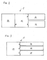
- FIGS. 2 and 3 show further preferred embodiments of fuel cell systems 1, which is designed according to the series concept of the present invention are.
- connection devices 15 of the base module 10 is provided such that a fuel tank 50 on the outside of the Base module can be connected.
- connection devices 12 and 13 for a fuel cell device 20 and a heat exchanger device 30 are provided in the base module 10 of FIG. 2, on the side that of the connection device 15 for the fuel tank 50 is opposite.
- the fuel cell device 20 and the heat exchanger device 30 attached to the same side of the base module 10.
- the size of the devices 20 and 30 changes only along one spatial direction when changing the power class, preferably to the same extent.
- the base module 10 of FIG. 3 differs from that shown in FIG. that here all three connection devices 12, 13, 15 on one side of the base module 10 are provided.
- the sequence shown, fuel tank 50 between Fuel cell device 20 and heat exchanger device 30 is only exemplary to understand. In the arrangement shown, more powerful fuel cell devices can be used 20 and correspondingly more powerful heat exchanger devices 30 also fuel tanks 50 with a higher volume are used, so that despite the increased consumption no shortening of the operating time or more frequent refilling of the tank 50 must be accepted.
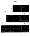
- FIG. 4 shows a to illustrate the series concept according to the invention
- a base module 10 which is in one and the same embodiment as the core of differently dimensioned fuel cell systems 1A, 1B, 1C is usable.
- the arrangement of the connection devices 12 and 13 is in this Base module 10 similar to that shown in Figure 2. The difference is here, however, as in FIG. 1, a fuel cartridge 150 is provided in the base module 10.
- the corresponding connection device is for the sake of clarity not shown.
- stack size and heat exchanger volume in the same way (linear) with the output power can scale a basic module that includes the system peripherals and electronics involves being used over a wide performance range. Only that performance-dependent devices, fuel cell device (“stack”) and heat exchanger device (“Heat exchanger”), and possibly a fuel tank, "grow” or “shrink” along the same direction.
- Stack and heat exchanger are arranged according to the invention in such a way that they are at Variation of the output power with minimal design effort, i.e. independently “grow” from the other components along the same spatial direction or "shrink".
- the concept can also be used in the event of varying product conditions. So the heat exchanger - and other cooling devices like fans The larger the desired max. outside temperature is. The heat exchanger and the fan (s) must therefore be arranged so that they can "grow” or “shrink" independently of the rest of the system.
Landscapes
- Life Sciences & Earth Sciences (AREA)
- Engineering & Computer Science (AREA)
- Manufacturing & Machinery (AREA)
- Sustainable Development (AREA)
- Sustainable Energy (AREA)
- Chemical & Material Sciences (AREA)
- Chemical Kinetics & Catalysis (AREA)
- Electrochemistry (AREA)
- General Chemical & Material Sciences (AREA)
- Fuel Cell (AREA)
Priority Applications (3)
| Application Number | Priority Date | Filing Date | Title |
|---|---|---|---|
| EP02027646A EP1429407A1 (fr) | 2002-12-11 | 2002-12-11 | Conception des séries de fabrication |
| AU2003279400A AU2003279400A1 (en) | 2002-12-11 | 2003-11-18 | Concept for a product line |
| PCT/EP2003/012899 WO2004054023A1 (fr) | 2002-12-11 | 2003-11-18 | Concept de gamme de fabrication |
Applications Claiming Priority (1)
| Application Number | Priority Date | Filing Date | Title |
|---|---|---|---|
| EP02027646A EP1429407A1 (fr) | 2002-12-11 | 2002-12-11 | Conception des séries de fabrication |
Publications (1)
| Publication Number | Publication Date |
|---|---|
| EP1429407A1 true EP1429407A1 (fr) | 2004-06-16 |
Family
ID=32319571
Family Applications (1)
| Application Number | Title | Priority Date | Filing Date |
|---|---|---|---|
| EP02027646A Withdrawn EP1429407A1 (fr) | 2002-12-11 | 2002-12-11 | Conception des séries de fabrication |
Country Status (3)
| Country | Link |
|---|---|
| EP (1) | EP1429407A1 (fr) |
| AU (1) | AU2003279400A1 (fr) |
| WO (1) | WO2004054023A1 (fr) |
Cited By (3)
| Publication number | Priority date | Publication date | Assignee | Title |
|---|---|---|---|---|
| US7833672B2 (en) | 2006-09-08 | 2010-11-16 | Samsung Sdi Co., Ltd. | Modular direct fuel cell system with integrated processor |
| WO2012150174A1 (fr) * | 2011-05-02 | 2012-11-08 | Deutsches Zentrum für Luft- und Raumfahrt e.V. | Jeu de pièces pour un dispositif de piles à combustible à structure modulaire comportant des boîtiers de module de construction identique pour différents composants du système |
| DE102017119222A1 (de) * | 2017-08-23 | 2019-02-28 | Dr. Ing. H.C. F. Porsche Aktiengesellschaft | Baukastensystem mit einem ersten und einem zweiten Modul |
Citations (5)
| Publication number | Priority date | Publication date | Assignee | Title |
|---|---|---|---|---|
| US4522894A (en) * | 1982-09-30 | 1985-06-11 | Engelhard Corporation | Fuel cell electric power production |
| US5567540A (en) * | 1992-10-02 | 1996-10-22 | Voltek, Inc. | Electrochemical power generating system |
| WO1998029917A1 (fr) * | 1996-12-26 | 1998-07-09 | Westinghouse Electric Corporation | Generateurs de piles a combustible a receptacle unique et a refroidissement integre, et centrales electriques utilisant un ensemble de ce type de generateurs |
| WO1999060644A1 (fr) * | 1998-05-20 | 1999-11-25 | Fraunhofer-Gesellschaft zur Förderung der angewandten Forschung e.V. | Systeme de piles a combustible |
| WO2000057506A1 (fr) * | 1999-03-19 | 2000-09-28 | Quantum Composites, Inc. | Melanges a mouler hautement conducteurs et plaques bipolaires de pile a combustible comprenant ces melanges |
-
2002
- 2002-12-11 EP EP02027646A patent/EP1429407A1/fr not_active Withdrawn
-
2003
- 2003-11-18 WO PCT/EP2003/012899 patent/WO2004054023A1/fr not_active Ceased
- 2003-11-18 AU AU2003279400A patent/AU2003279400A1/en not_active Abandoned
Patent Citations (5)
| Publication number | Priority date | Publication date | Assignee | Title |
|---|---|---|---|---|
| US4522894A (en) * | 1982-09-30 | 1985-06-11 | Engelhard Corporation | Fuel cell electric power production |
| US5567540A (en) * | 1992-10-02 | 1996-10-22 | Voltek, Inc. | Electrochemical power generating system |
| WO1998029917A1 (fr) * | 1996-12-26 | 1998-07-09 | Westinghouse Electric Corporation | Generateurs de piles a combustible a receptacle unique et a refroidissement integre, et centrales electriques utilisant un ensemble de ce type de generateurs |
| WO1999060644A1 (fr) * | 1998-05-20 | 1999-11-25 | Fraunhofer-Gesellschaft zur Förderung der angewandten Forschung e.V. | Systeme de piles a combustible |
| WO2000057506A1 (fr) * | 1999-03-19 | 2000-09-28 | Quantum Composites, Inc. | Melanges a mouler hautement conducteurs et plaques bipolaires de pile a combustible comprenant ces melanges |
Cited By (4)
| Publication number | Priority date | Publication date | Assignee | Title |
|---|---|---|---|---|
| US7833672B2 (en) | 2006-09-08 | 2010-11-16 | Samsung Sdi Co., Ltd. | Modular direct fuel cell system with integrated processor |
| WO2012150174A1 (fr) * | 2011-05-02 | 2012-11-08 | Deutsches Zentrum für Luft- und Raumfahrt e.V. | Jeu de pièces pour un dispositif de piles à combustible à structure modulaire comportant des boîtiers de module de construction identique pour différents composants du système |
| DE102017119222A1 (de) * | 2017-08-23 | 2019-02-28 | Dr. Ing. H.C. F. Porsche Aktiengesellschaft | Baukastensystem mit einem ersten und einem zweiten Modul |
| DE102017119222B4 (de) | 2017-08-23 | 2025-06-12 | Dr. Ing. H.C. F. Porsche Aktiengesellschaft | Baukastensystem mit einem ersten und einem zweiten Modul |
Also Published As
| Publication number | Publication date |
|---|---|
| WO2004054023A1 (fr) | 2004-06-24 |
| AU2003279400A1 (en) | 2004-06-30 |
Similar Documents
| Publication | Publication Date | Title |
|---|---|---|
| DE10139071B4 (de) | Wandlervorrichtung | |
| EP0760253A1 (fr) | Mélangeur statique pour fluides visqueux | |
| DE10235479A1 (de) | Energieverteileinrichtung und Zwischenverbinder darin | |
| DE69401083T2 (de) | Verpackungssystem mit Speicherrohren für elektrische Verbinder | |
| WO1997037420A1 (fr) | Systeme public de distribution d'energie, procede d'execution de livraisons d'energie et composants pour ce systeme | |
| EP1429407A1 (fr) | Conception des séries de fabrication | |
| EP0939976B1 (fr) | Dispositif de codage de prises de fiches | |
| WO1991013478A1 (fr) | Element regulateur de l'excitation d'un relais | |
| DE102009049644A1 (de) | Elektrizitätszähler | |
| EP1149292A1 (fr) | Dispositif permettant de tester des cables dotes de fiches | |
| EP2071245A2 (fr) | Installation de chauffage | |
| EP0987487A1 (fr) | Bloc de détente et de mélange de gaz | |
| EP1273397B1 (fr) | Mallete à outil et mallete à chargeur de batterie pour un outil à main électrique et assortiment de malletes | |
| EP0770946B1 (fr) | Procédé pour concevoir automatiquement la redondance optimale pour des mesures dans le système de controle des centrales électriques | |
| DE9316757U1 (de) | Pumpenstand mit einer Pumpe | |
| DE202018101111U1 (de) | Kraftfahrzeugsitzsystem | |
| DE4413453B4 (de) | Integrierbares elektronisches Gerät | |
| DE8905361U1 (de) | Codiervorrichtung für auf eine Rückwandverdrahtung aufsteckbare elektrische Baugruppe | |
| AT390506B (de) | Einrichtung bei verlustwaerme erzeugenden anlagen | |
| EP2442076A1 (fr) | Compteur électrique | |
| DE102024131914A1 (de) | Modulares Rechnergerät, insbesondere für Verkaufsstellen | |
| DE9305316U1 (de) | Maßeinheitliche Kochmulde | |
| DE2856402A1 (de) | Bedienungsgeraet zur modellfernsteuerung | |
| CH691636A5 (de) | Heiz- oder klimatechnische Vorrichtung mit Typenschild und Verfahren zu deren Herstellung. | |
| EP1153466A1 (fr) | Systeme lumineux de secours |
Legal Events
| Date | Code | Title | Description |
|---|---|---|---|
| PUAI | Public reference made under article 153(3) epc to a published international application that has entered the european phase |
Free format text: ORIGINAL CODE: 0009012 |
|
| 17P | Request for examination filed |
Effective date: 20031112 |
|
| AK | Designated contracting states |
Kind code of ref document: A1 Designated state(s): AT BE BG CH CY CZ DE DK EE ES FI FR GB GR IE IT LI LU MC NL PT SE SI SK TR |
|
| AX | Request for extension of the european patent |
Extension state: AL LT LV MK RO |
|
| RAP1 | Party data changed (applicant data changed or rights of an application transferred) |
Owner name: SFC SMART FUEL CELL AG |
|
| RAP1 | Party data changed (applicant data changed or rights of an application transferred) |
Owner name: SFC SMART FUEL CELL AG |
|
| AKX | Designation fees paid |
Designated state(s): AT BE BG CH CY CZ DE DK EE ES FI FR GB GR IE IT LI LU MC NL PT SE SI SK TR |
|
| 17Q | First examination report despatched |
Effective date: 20050913 |
|
| STAA | Information on the status of an ep patent application or granted ep patent |
Free format text: STATUS: THE APPLICATION IS DEEMED TO BE WITHDRAWN |
|
| 18D | Application deemed to be withdrawn |
Effective date: 20070710 |