EP2463868B1 - Ruban en alliage amorphe magnétique souple, procédé pour sa fabrication et noyau magnétique l'utilisant - Google Patents
Ruban en alliage amorphe magnétique souple, procédé pour sa fabrication et noyau magnétique l'utilisant Download PDFInfo
- Publication number
- EP2463868B1 EP2463868B1 EP10815497.2A EP10815497A EP2463868B1 EP 2463868 B1 EP2463868 B1 EP 2463868B1 EP 10815497 A EP10815497 A EP 10815497A EP 2463868 B1 EP2463868 B1 EP 2463868B1
- Authority
- EP
- European Patent Office
- Prior art keywords
- magnetic
- amorphous alloy
- soft
- alloy ribbon
- recesses
- Prior art date
- Legal status (The legal status is an assumption and is not a legal conclusion. Google has not performed a legal analysis and makes no representation as to the accuracy of the status listed.)
- Active
Links
Images




Classifications
-
- C—CHEMISTRY; METALLURGY
- C22—METALLURGY; FERROUS OR NON-FERROUS ALLOYS; TREATMENT OF ALLOYS OR NON-FERROUS METALS
- C22C—ALLOYS
- C22C38/00—Ferrous alloys, e.g. steel alloys
- C22C38/02—Ferrous alloys, e.g. steel alloys containing silicon
-
- C—CHEMISTRY; METALLURGY
- C22—METALLURGY; FERROUS OR NON-FERROUS ALLOYS; TREATMENT OF ALLOYS OR NON-FERROUS METALS
- C22C—ALLOYS
- C22C45/00—Amorphous alloys
- C22C45/02—Amorphous alloys with iron as the major constituent
-
- H—ELECTRICITY
- H01—ELECTRIC ELEMENTS
- H01F—MAGNETS; INDUCTANCES; TRANSFORMERS; SELECTION OF MATERIALS FOR THEIR MAGNETIC PROPERTIES
- H01F1/00—Magnets or magnetic bodies characterised by the magnetic materials therefor; Selection of materials for their magnetic properties
- H01F1/01—Magnets or magnetic bodies characterised by the magnetic materials therefor; Selection of materials for their magnetic properties of inorganic materials
- H01F1/03—Magnets or magnetic bodies characterised by the magnetic materials therefor; Selection of materials for their magnetic properties of inorganic materials characterised by their coercivity
- H01F1/12—Magnets or magnetic bodies characterised by the magnetic materials therefor; Selection of materials for their magnetic properties of inorganic materials characterised by their coercivity of soft-magnetic materials
- H01F1/14—Magnets or magnetic bodies characterised by the magnetic materials therefor; Selection of materials for their magnetic properties of inorganic materials characterised by their coercivity of soft-magnetic materials metals or alloys
- H01F1/147—Alloys characterised by their composition
- H01F1/153—Amorphous metallic alloys, e.g. glassy metals
- H01F1/15341—Preparation processes therefor
-
- H—ELECTRICITY
- H01—ELECTRIC ELEMENTS
- H01F—MAGNETS; INDUCTANCES; TRANSFORMERS; SELECTION OF MATERIALS FOR THEIR MAGNETIC PROPERTIES
- H01F41/00—Apparatus or processes specially adapted for manufacturing or assembling magnets, inductances or transformers; Apparatus or processes specially adapted for manufacturing materials characterised by their magnetic properties
- H01F41/02—Apparatus or processes specially adapted for manufacturing or assembling magnets, inductances or transformers; Apparatus or processes specially adapted for manufacturing materials characterised by their magnetic properties for manufacturing cores, coils, or magnets
- H01F41/0206—Manufacturing of magnetic cores by mechanical means
- H01F41/0213—Manufacturing of magnetic circuits made from strip(s) or ribbon(s)
- H01F41/0226—Manufacturing of magnetic circuits made from strip(s) or ribbon(s) from amorphous ribbons
-
- Y—GENERAL TAGGING OF NEW TECHNOLOGICAL DEVELOPMENTS; GENERAL TAGGING OF CROSS-SECTIONAL TECHNOLOGIES SPANNING OVER SEVERAL SECTIONS OF THE IPC; TECHNICAL SUBJECTS COVERED BY FORMER USPC CROSS-REFERENCE ART COLLECTIONS [XRACs] AND DIGESTS
- Y10—TECHNICAL SUBJECTS COVERED BY FORMER USPC
- Y10T—TECHNICAL SUBJECTS COVERED BY FORMER US CLASSIFICATION
- Y10T29/00—Metal working
- Y10T29/49—Method of mechanical manufacture
- Y10T29/49002—Electrical device making
- Y10T29/4902—Electromagnet, transformer or inductor
- Y10T29/49075—Electromagnet, transformer or inductor including permanent magnet or core
- Y10T29/49078—Laminated
-
- Y—GENERAL TAGGING OF NEW TECHNOLOGICAL DEVELOPMENTS; GENERAL TAGGING OF CROSS-SECTIONAL TECHNOLOGIES SPANNING OVER SEVERAL SECTIONS OF THE IPC; TECHNICAL SUBJECTS COVERED BY FORMER USPC CROSS-REFERENCE ART COLLECTIONS [XRACs] AND DIGESTS
- Y10—TECHNICAL SUBJECTS COVERED BY FORMER USPC
- Y10T—TECHNICAL SUBJECTS COVERED BY FORMER US CLASSIFICATION
- Y10T428/00—Stock material or miscellaneous articles
- Y10T428/12—All metal or with adjacent metals
- Y10T428/12389—All metal or with adjacent metals having variation in thickness
Definitions
- the present invention relates to a soft-magnetic, amorphous alloy ribbon with low loss and apparent power and a high lamination factor and suitable for distribution transformers, high-frequency transformers, saturable reactors, magnetic switches, etc., its production method, and a magnetic core constituted by such soft-magnetic, amorphous alloy ribbon.
- Soft-magnetic, Fe- or Co-based, amorphous alloys produced by liquid quenching methods such as a single roll method, etc. are free from magnetocrystalline anisotropy because of no crystal grains, having small magnetic hysteresis loss, low coercivity and excellent soft magnetic properties. Because of these properties, amorphous alloy ribbons are used in magnetic cores for various transformers, choke coils, saturable reactors and magnetic switches, magnetic sensors, etc. Particularly, Fe-based, amorphous alloy ribbons have relatively high saturation magnetic flux densities Bs, low coercivity, and low loss, gathering much attention as energy-saving, soft-magnetic materials. Among the Fe-based, amorphous alloy ribbons, amorphous Fe-Si-B alloy ribbons having excellent thermal stability are widely used in transformer cores (see, for example, JP 2006-45662 A ).
- amorphous Fe-Si-B alloys have low coercivity and small magnetic hysteresis loss, it is known that their eddy current loss (iron loss - hysteresis loss) in a broad sense is larger than a classical eddy current loss determined under the assumption of uniform magnetization by tens of times to about 100 times.
- the difference between the broad-sense eddy current loss and the classical eddy current loss is called anomalous eddy current loss or excess loss, which is mainly caused by non-uniform magnetization change.
- Known as methods for reducing anomalous eddy current loss in amorphous alloy ribbons are a method of mechanically scratching a surface of an amorphous alloy ribbon ( JP 62-49964 B ), a method of intermittently heat-treating a surface of an amorphous alloy ribbon by an electron beam, a laser beam, an electric arc, a spark, contact with a high-temperature object, etc.
- an amorphous alloy ribbon surface is melted locally and instantaneously by the irradiation of laser pulses in a transverse direction, and then rapidly solidified to form substantially circular recesses in lines.
- Each recess has a diameter of 0.5 mm or less, particularly 200-250 ⁇ m when the recesses are formed before annealing, and 50-100 ⁇ m when they are formed after annealing.
- the recesses have an average interval of 1-20 mm. In a diameter range of 50-250 ⁇ m, the iron loss decreases as the diameter increases.
- Example 1 of JP 3-32886 B recesses having diameters of about 50-250 ⁇ m are formed with 5-mm intervals by a YAG laser on a 65- ⁇ m-thick, amorphous alloy ribbon.
- Molten alloy splashes are observed around recesses formed by the method of JP 3-32886 B . This appears to be due to the fact that to form recesses with large intervals on a relatively thick amorphous alloy ribbon, deep recesses are formed by a large irradiation energy density of laser beams. It has been found, however, that when deep recesses are formed at such a large irradiation energy density of laser beams that splashes are formed around the recesses, particularly a relatively thin amorphous alloy ribbon would suffer increase in apparent power (exciting VA) and decrease in a space factor despite the decreased iron loss. Increase in the apparent power of the amorphous alloy ribbon results in larger sound noise when used for distribution transformers, etc.
- the space factor has the same meaning as a lamination factor LF, smaller LF providing larger ribbon-laminated cores.
- Increase in the apparent power and decrease in the lamination factor have more serious problems on thinner amorphous alloy ribbons, because thinner amorphous alloy ribbons are more influenced by laser-scribed surface conditions than thicker amorphous alloy ribbons.
- the method of JP 3-32888 B for dividing magnetic domains comprises the steps of irradiating an amorphous alloy ribbon with laser pulses having a beam diameter of 0.5 mm or less with an energy density of 0.02-1.0 J/mm 2 per one pulse in a transverse direction, so that an amorphous alloy ribbon surface is locally and instantaneously melted and rapidly solidified, thereby forming substantially circular recesses at a line density of 10% or more, and annealing the ribbon.
- This method is an improvement of the method of JP 3-32886 B , optimizing the distribution density of recesses and the timing of annealing to improve iron loss and exciting properties.
- Example 1 of JP 3-32888 B a 65- ⁇ m-thick, amorphous alloy ribbon is irradiated with laser pulses having a beam diameter of 0.2 mm and an energy density of about 0.3 J/mm 2 , which is supplied from a YAG laser, to form lines of recesses at line density of about 70%.
- molten alloy splashes are observed around recesses shown in JP 3-32888 B . This seems to be due to the fact that deep recesses are formed by a large irradiation energy density of laser beams. As a result, the apparent power increases despite the decreased iron loss.
- JP 3-32888 B describes an energy density of 0.02-1.0 J/mm 2 per one pulse.
- laser pulses having as low energy as near 0.02 J/mm 2 are projected to an amorphous alloy ribbon as thick as 65 ⁇ m, the resultant recesses are not fully deep relative to the thickness of the amorphous alloy ribbon, failing to obtain a sufficient iron loss-reducing effect.
- JP 2-53935 B The method of JP 2-53935 B is the same as those described in JP 3-32886 B and JP 3-32888 B , in that an amorphous alloy ribbon is irradiated with laser beams in a transverse direction to melt the surface locally.
- the former is different from the latter in that molten portions are crystallized regions.
- the crystallized regions are formed by the scanning of laser beams, etc., a ratio d/D of their depth d to the thickness D of the amorphous alloy ribbon being 0.1 or more, and the percentage of the crystallized regions being 8% or less by volume based on the entire ribbon.
- the molten portions are crystallized regions, the iron loss is not sufficiently reduced.
- an object of the present invention is to provide a soft-magnetic, amorphous alloy ribbon having low iron loss and apparent power as well as a high lamination factor, its production method, and a magnetic core constituted by such soft-magnetic, amorphous alloy ribbon.
- the soft-magnetic, amorphous alloy ribbon of the present invention is formed by a rapid quenching method, and has transverse lines of recesses formed on its surface by laser beams with predetermined longitudinal intervals, with a doughnut-shaped projection formed around each recess; the doughnut-shaped projections having smooth surfaces substantially free from splashes of the alloy melted by the irradiation of laser beams of 2-5 J/ cm 2 , and a height t 2 of 2 ⁇ m or less; and a ratio t 1 /T of the depth t 1 of the recesses to the thickness T of the ribbon being in a range of 0.025-0.18, thereby having low iron loss and low apparent power.
- the openings of the recesses are preferably substantially circular.
- the height t 2 of the doughnut-shaped projections is preferably 0.5-2 ⁇ m, more preferably 0.5-1.8 ⁇ m.
- a ratio t 1 /T of the depth t 1 of the recesses to the thickness T of the ribbon is preferably in a range of 0.03-0.15.
- the thickness T of the ribbon is preferably 30 ⁇ m or less.
- the t 1 /T ratio can be made small, suppressing increase in the apparent power.
- a ratio t/T of the total t of the depth t 1 of the recesses and the height t 2 of the doughnut-shaped projections to the thickness T of the ribbon is preferably 0.2 or less, more preferably 0.16 or less.
- the soft-magnetic, amorphous alloy ribbon is preferably made of an Fe-Si-B alloy.
- a surface of the amorphous alloy ribbon, which is irradiated with laser beams preferably has reflectance of 15-80% at a wavelength ⁇ of 1000 nm.
- the term "reflectance” used herein means a ratio of laser beams reflected in an incident direction to incident laser beams, when the laser beams are vertically projected to the alloy ribbon surface. Accordingly, the reflectance of 10% means that 10% of laser beams are reflected in the incident direction, and that the total of laser beams diffuse-reflected to other directions and those absorbed by the alloy ribbon is 90%. With reflectance in this range, the irradiation energy density of laser beams is not excessively large or small, easily forming recesses surrounded by doughnut-shaped projections having smooth surfaces substantially free from molten alloy splashes.
- the method of the present invention, according to claim 10 for producing a soft-magnetic, amorphous alloy ribbon having low iron loss and low apparent power comprises irradiating a surface of a soft-magnetic, amorphous alloy ribbon produced by a rapid quenching method with laser beam pulses successively in a transverse direction with predetermined longitudinal intervals, to form transverse lines of recesses; the irradiation energy density of the laser beam pulses being controlled at 2-5 J/cm 2 , such that (a) a doughnut-shaped projection is formed around each recess, that (b) the doughnut-shaped projections have substantially no molten alloy splashes to have smooth surfaces, that (c) the doughnut-shaped projections have a height t 2 of 2 ⁇ m or less, and that (d) a ratio t 1 /T of the depth t 1 of the recesses to the thickness T of the ribbon is in a range of 0.025-0.18, thereby dividing magnetic domains in the amorphous alloy
- the amorphous alloy ribbon is preferably irradiated with the laser beam pulses passing through a galvanometer scanner or a polygon scanner and an f ⁇ lens.
- the laser beam pulses are preferably generated by a fiber laser. Because the fiber laser capable of highly focusing to a small spot is resistant to thermal influence, it can suppress the formation of molten alloy splashes around the recesses, thereby forming doughnut-shaped projections having smooth surfaces. Also, because of a large depth of focus, high-precision depth control can be conducted by the fiber laser, thereby forming shallow recesses on thin alloy ribbons.
- t/T ratio of 0.2 or less, it is preferable to adjust the depth of focus of the f ⁇ lens, or to control the irradiation energy density of laser beams per one pulse.
- the irradiation energy density of the laser beam pulses is 2-5 J/cm 2 , preferably 2.5-4 J/cm 2 . J/cm 2 .
- a magnetic core is obtained by laminating or winding the above soft-magnetic, amorphous alloy ribbon. This magnetic core has low iron loss and a high lamination factor.
- the soft-magnetic, amorphous alloy ribbon is preferably provided with the above recesses, and then heat-treated in a magnetic field oriented in a magnetic path direction. This reduces core loss at low frequencies, and apparent power contributing to the generation of sound noise.
- Amorphous alloys usable in the present invention include Fe-B alloys, Fe-Si-B alloys, Fe-Si-B-C alloys, Fe-Si-B-P alloys, Fe-Si-B-C-P alloys, Fe-P-B alloys, etc., and alloys based on Fe, Si and B are preferable because they are resistant to embrittlement by laser beam irradiation, and easily subject to working such as cutting, etc.
- the amorphous Fe-Si-B alloy preferably has a composition comprising 1-15 atomic % of Si and 8-20 atomic % of B, the balance being substantially Fe and inevitable impurities.
- the Fe-Si-B-C alloy preferably has a composition comprising 1-15 atomic % of Si, 8-20 atomic % of B, and 3 atomic % or less of C, the balance being Fe and inevitable impurities.
- the inclusion of 10 atomic % or less of Si and 17 atomic % or less of B provides high Bs, and drastically reduces iron loss due to the irradiation of laser beams, making the production of amorphous alloys easy.
- the amorphous alloy may contain at least one selected from the group consisting of Co, Ni, Mn, Cr, V, Mo, Nb, Ta, Hf, Zr, Ti, Cu, Au, Ag, Sn, Ge, Re, Ru, Zn, In and Ga, in a proportion of 5 atomic % or less in total to Fe.
- the inevitable impurities are S, O, N, Al, etc.
- Amorphous alloy ribbons are produced preferably by a liquid quenching method, such as a single roll method or a double roll method.
- the amorphous alloy ribbon which are irradiated with laser beams, preferably has a surface having reflectance R (%) of 15-80% at a wavelength ⁇ of 1000 nm.
- the reflectance R (%) is expressed by 100 x ⁇ r/ ⁇ , wherein ⁇ represents the quantity of luminous flux vertically projected to the ribbon surface, and ⁇ r represents the quantity of luminous flux reflected from the ribbon surface in the incident direction.
- ⁇ and ⁇ r are measured by a spectrometer (JASCO V-570 available from JASCO Corporation) at a wavelength of 1000 nm (close to the wavelength of laser beams used).
- one or both surfaces of the amorphous alloy ribbon may be coated with an insulating layer of SiO 2 , Al 2 O 3 , MgO, etc.
- an insulating layer of SiO 2 , Al 2 O 3 , MgO, etc.
- a YAG laser, a CO 2 gas laser, a fiber laser, etc. may be used as an apparatus for generating laser beam pulses.
- a fiber laser capable of stably generating high-power, high-frequency laser beam pulses for a long period of time.
- laser beams introduced into a fiber are oscillated by diffraction gratings on both ends thereof by the principle of fiber Bragg grating (FBG).
- laser beams are excited in an elongated fiber, they are not subject to a thermal lens effect leading to their quality deterioration due to a temperature gradient occurring in the crystals. Further, because a fiber core is as thin as several microns, even high-power laser beams are conveyed in a single mode with a reduced beam diameter, resulting in high-energy-density laser beams. In addition, because of a large depth of focus, lines of recesses can be formed precisely on a ribbon as wide as 200 mm or more.
- the pulse width of the fiber laser is usually from about microseconds to about picoseconds, though it may be on the femtosecond level.
- the laser beams have wavelength of about 250-1100 nm, and they are mostly used in a wavelength of about 1000 nm.
- the beam diameter of the laser beams is preferably 10-300 ⁇ m, more preferably 20-100 ⁇ m, most preferably 30-90 ⁇ m.
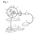
- Fig. 1 shows one example of laser-beam-radiating apparatuses.
- This apparatus comprises a laser oscillator (fiber laser) 10, a collimator 12, a beam expander 13, a galvanometer scanner 14, and a f ⁇ lens 15.
- Laser beam pulses L (for example, wavelength: 1065 ⁇ m) generated by the laser oscillator 10 are transmitted via the fiber 11 to the collimator 12, in which they are made parallel.
- the diameters of parallel laser beams L are expanded by the beam expander 13.
- After passing through the galvanometer scanner 14, they are collected by the f ⁇ lens 15, and irradiated onto the amorphous alloy ribbon 1 placed on a table 5 movable in both X and Y directions.
- the laser scribing is conducted preferably before the heat treatment. Because recesses formed on a soft-magnetic, amorphous alloy ribbon by the irradiation of laser beams are not crystallized, the ribbon has such good workability that it is easily cut and bent to produce magnetic cores.
- Fig. 2(a) schematically shows the cross section of a substantially circular recess 2 and a surrounding annular projection (rim) 3 formed on the soft-magnetic, amorphous alloy ribbon 1.
- substantially circular used herein means, as shown in Fig. 2(b) , that the contour of each recess 2 needs not to be a true circle, but may be a deformed circle or an ellipse.
- a ratio of a major axis Da to a minor axis Db, which represents the degree of deformation of the deformed circle or the ellipse, is preferably within 1.5.
- the diameter D 1 of the recess 2 is a diameter of the opening of the recess 2 at a level of a straight line 1a passing the surface of the ribbon 1
- the depth t 1 of the recess 2 is a distance between the straight line 1a and the bottom of the recess 2
- the outer diameter D 2 of the annular projection 3 is an outer diameter of the annular projection 3 at a level of the straight line 1a
- the height t 2 of the annular projection 3 is a distance between the straight line 1a and the apex of the annular projection 3
- the width W of the annular projection 3 is [(D 2 - D 1 )/2] determined at a level of the straight line 1a. Any of these parameters are expressed by average values determined from recesses 2 and annular projections 3 in plural (3 or more) transverse lines of recesses.
- the resultant recesses 2 and surrounding annular projections 3 are substantially in an amorphous state. Because this rapid solidification generates stress near the recesses 2, forming magnetic domains whose magnetization is oriented in the depth direction of the ribbon, it is presumed that the apparent power increases. Stress increases not only by the height of the annular projections 3, but also by melt splashes attached around the recesses 2. On the other hand, the division of magnetic domains by the recesses 2 reduces iron loss, resulting in reduced apparent power.
- annular projections having a doughnut shape (simply called “doughnut-shaped projections") having smooth surfaces substantially free from molten alloy splashes, with height t 2 limited to 2 ⁇ m or less, are formed around the recesses by controlling the irradiation energy of laser beams to the thickness T of the amorphous alloy ribbon.
- the term "smooth surfaces substantially free from splashes” used herein means, as shown in Fig. 2(b) , that annular projections 3 observed in an optical photomicrograph (50 times) have smooth inside and outside contours 3a, 3b without projections, with the same surface roughness between the annular projections 3 and other portions of the amorphous alloy ribbon 1.
- the “doughnut shape” has smooth surface and contour, unless otherwise mentioned. Accordingly, for example, when the inside and outside contours of annular projections 3 are ragged in recesses B, C, D as shown in Fig. 5 , the requirement of "smooth surfaces substantially free from splashes" is not met. By the above requirement, it is possible to reduce the iron loss while effectively suppressing increase in the apparent power.
- the height t 2 of the doughnut-shaped projections 3 is more preferably 1.8 ⁇ m or less, most preferably 0.3-1.8 ⁇ m.
- t 1 /T should be in a range of 0.025-0.18, preferably 0.03-0.15, more preferably 0.03-0.13.
- the thickness T of the amorphous alloy ribbon 1 is preferably 30 ⁇ m or less. When the thickness T of the amorphous alloy ribbon 1 is more than 30 ⁇ m, the value of t 1 is large for the same t 1 /T, resulting in larger apparent power.
- t/T is 0.2 or less, increase in the apparent power is suppressed.
- the ratio t/T is preferably 0.18 or less, more preferably 0.16 or less.
- the diameter D 1 of the recesses 2 is preferably 20-50 ⁇ m, more preferably 20-40 ⁇ m, most preferably 24-38 ⁇ m.
- the outer diameter D 2 of the doughnut-shaped projections 3 is preferably 100 ⁇ m or less, more preferably 80 ⁇ m or less, most preferably 76 ⁇ m or less.
- the lower limit of the outer diameter D 2 is preferably 30 ⁇ m.
- the longitudinal intervals of lines of recesses is generally 2-20 mm, for example, preferably 3-10 mm.
- recesses may be arranged with intervals, or adjacent recesses may be overlapped.
- the number density of recesses in the transverse lines is 2/mm to 25/mm, preferably 4/mm to 20/mm.
- Magnetic cores obtained by laminating or winding the soft-magnetic, amorphous alloy ribbons of the present invention have low iron loss with suppressed apparent power and high lamination factors LF.
- a heat treatment in a magnetic field oriented in a magnetic path direction of the formed magnetic core can reduce a core loss (hysteresis loss) and apparent power, resulting in reduced sound noise.
- a freely solidified surface of this alloy ribbon had reflectance R of 68.3% to light having a wavelength of 1000 nm. As shown in Fig.
- the freely solidified surface of this amorphous alloy ribbon was scanned with laser beam pulses having a wavelength of 1065 nm, a pulse width of 550 ns and a beam diameter of 90 ⁇ m at an irradiation energy density of 2.5 J/cm 2 , which were sent from the fiber laser 10 via the galvanometer scanner (mirror) 14, to form transverse lines of recesses as shown in Fig. 3 .
- the number density of recesses in transverse lines was 2 /mm, and the longitudinal intervals D L of the lines of recesses were 5 mm.
- Figs. 4(a) and 4(b) show the electron photomicrographs of recesses and annular projections surrounding them.
- the annular projections in a doughnut shape had smooth surfaces substantially free from splashes of the alloy melted by the irradiation of laser beams.
- Transmission electron microscopic observation revealed that there were no crystal phases in the recesses and the doughnut-shaped projections. This confirms that the recesses and the doughnut-shaped projections were constituted by an amorphous phase.
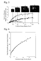
- Fig. 5 shows the relation between the irradiation energy density of laser beams and the height t 2 of annular projections
- Fig. 6 shows the relation between the irradiation energy density of the same laser beams and the outer diameter D 2 of the annular projections.
- the annular projections 3 in a doughnut shape had heights t 2 of 2 ⁇ m or less and outer diameters D 2 of 90 ⁇ m or less.
- the heights t 2 and outer diameters D 2 of the doughnut-shaped projections change depending not only on laser beams but also on irradiation conditions such as pulse width, etc.
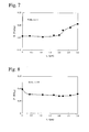
- Fig. 7 shows the relation between the height t 2 of annular projections and the apparent power S at 50 Hz and 1.3 T. As is clear from Fig. 7 , t 2 of 2 ⁇ m or less provided a low apparent power S, but when t 2 exceeded 2 ⁇ m, the apparent power S increased drastically. Fig.
- FIG. 8 shows the relation between the height t 2 of annular projections and the iron loss P at 50 Hz and 1.3 T.
- the formation of recesses decreased the iron loss P, but t 2 of more than 2 ⁇ m provided slightly increased iron loss P.
- the iron loss P tends to decrease as t 2 increases (as the irradiation energy density of laser beams increases).
- the apparent power S is substantially constant at t 2 of 2 ⁇ m or less, it tends to increase drastically when t 2 exceeds 2 ⁇ m. Accordingly, to meet both requirements of low iron loss and low apparent power, the height t 2 of annular projections should be 2 ⁇ m or less, particularly in a range of 0.5-2 ⁇ m.
- amorphous alloy ribbons having various thicknesses were produced from alloy melts having the compositions shown in Table 1 by a single roll method.
- the thickness T of each amorphous alloy ribbon, and the reflectance R of a freely solidified surface of each amorphous alloy ribbon to light having a wavelength of 1000 nm are shown in Table 1. As shown in Fig.
- laser beam pulses having a wavelength of 1065 nm, a pulse width of 500 ns and a beam diameter of 60 ⁇ m were supplied from a fiber laser 10 via a galvanometer scanner (mirror) 14, to scan a freely solidified surface of each amorphous alloy ribbon with an irradiation energy density of 2-5 J/ cm 2 , ( ⁇ 2 J/cm 2 comparative examples), thereby forming transverse lines of recesses with longitudinal intervals of 5 mm.
- the number density of recesses in the lines was 4 /mm.
- the diameter D 1 and depth t 1 of the recesses, and the outer diameter D 2 , height t 2 and width W of the annular projections were measured on plural lines of recesses, and averaged.
- Each alloy ribbon provided with recesses was cut to 120 mm, and heat-treated at 330-370°C for 1 hour in a magnetic field of 1.6 kA/m oriented in the longitudinal direction of the ribbon, to provide a single-plate sample, whose iron loss P (W/kg) and apparent power S (VA/kg) were measured at 50 Hz and 1.3 T. Also, 20 amorphous alloy ribbon pieces provided with recesses were laminated to measure a lamination factor LF. These measurement results are shown in Table 1.
- the freely solidified surface of this alloy ribbon had reflectance R of 69.5% to light having a wavelength of 1000 nm. As shown in Fig.
- laser beam pulses having a wavelength of 1065 nm, a pulse width of 550 ns and a beam diameter of 90 ⁇ m were supplied from a fiber laser via a galvanometer scanner (mirror), to scan the freely solidified surface of this amorphous alloy ribbon with an irradiation energy density of 2.5 J/cm 2 in a transverse direction, thereby forming transverse lines of recesses with longitudinal intervals of 5 mm as shown in Fig. 3 .
- the number density of recesses in the lines was 2/mm.
- the depth t 1 of the recesses was 1.2 ⁇ m, the height t 2 of doughnut-shaped projections was 0.5 ⁇ m, t/T was 0.07, and the lamination factor LF was 89%.
- This alloy ribbon was cut to pieces as long as 120 mm, and 20 pieces were laminated to produce a magnetic core.
- This magnetic core was heat-treated at 330°C for 1 hour in a magnetic field of 1.2 kA/m oriented in the longitudinal direction of the ribbon. A coil was wound around this magnetic core, and excited to 1.4 T at 50 Hz to measure sound noise.
- a freely solidified surface of the same amorphous alloy ribbon as in Example 5 was scanned with laser beam pulses having a wavelength of 1065 nm, a pulse width of 550 ns and a beam diameter of 90 ⁇ m with an irradiation energy density of 6.6 J/cm 2 , to form lines of recesses.
- the depth t 1 of the recesses was 5.5 ⁇ m
- the height t 2 of annular projections was 2.8 ⁇ m
- t/T was 0.33
- the lamination factor LF was 86%.
- a magnetic core was produced from this alloy ribbon by the same method as in Example 5, and a coil was wound around it and excited to 1.4 T at 50 Hz to measure sound noise. As a result, the magnetic core noise was 53 dB in Example 5 and 63 dB in Comparative Example 1. It was thus confirmed that the magnetic core of the present invention had low sound noise.
- a freely solidified surface of this alloy ribbon had reflectance R of 72.1 % to light having a wavelength of 1000 nm. As shown in Fig.
- laser beam pulses having a wavelength of 1065 ⁇ m, a pulse width of 500 ns and a beam diameter of 60 ⁇ m were supplied from a fiber laser 10 via a galvanometer scanner (mirror) 14, to scan the freely solidified surface of this amorphous alloy ribbon with irradiation energy densities of 2.7 J/cm 2 , 3.0 J/cm 2 , 6.2 J/cm 2 and 11.2 J/cm 2 , respectively, in a transverse direction, thereby forming transverse lines of recesses having various number densities n of recesses with longitudinal intervals of 5 mm.
- Each alloy ribbon was cut to 120 mm, and heat-treated at 350°C for 1 hour in a magnetic field of 1.2 kA/m in the longitudinal direction of the ribbon to provide a single-plate sample, whose iron loss P (W/kg) and apparent power S (VA/kg) were measured at 50 Hz and 1.3 T.
- Fig. 9 shows the relation between the core loss P and the number density n (/mm) of recesses at each irradiation energy density.
- n the iron loss P decreased, and the larger the energy density became, the more the iron loss P decreased.
- the formation of recesses dividing magnetic domains leads to lower iron loss P.
- a small number density n of recesses provides a relatively high iron loss P, and increase in the number density n of recesses results in the decrease of the iron loss P.
- the number density n of recesses is more than 20, the effect of dividing magnetic domains is saturated, making it difficult to reduce the iron loss P.
- the iron loss P does not increase even if the number density n of recesses is more than 20. However, at an irradiation energy density of 11.2 J/cm 2 , the iron loss P increased when the number density n of recesses exceeded about 12. This is in agreement with the tendency shown in Fig. 8 , in which at an irradiation energy density providing annular projections having a height t 2 exceeding about 2.5 ⁇ m, the iron loss P rather increases.
- Fig. 10 shows the relation between the number density n (/mm) of recesses and the apparent power S.
- n increases at each energy density, the apparent power S tends to decrease and then increase.
- stress has larger influence than the apparent power S.
- the division of magnetic domains results in decreased iron loss P, the apparent power S decreases as the iron loss P decreases.
- magnetic domains having a magnetization direction in the depth direction are formed because of stress in the recesses, resulting in increased apparent power S.
- the number density n of recesses providing low iron loss and low apparent power is substantially 2-20 /mm.
- the apparent power S increases when the number density n of recesses exceeds about 5, at a rate decreasing as the irradiation energy density becomes smaller.
- the irradiation energy density is preferably as small as possible to suppress increase in the apparent power S.
- the irradiation energy density is preferably 5 J/cm 2 or less and 2 J/cm 2 or more, more preferably 2.5-4 J/cm 2 .
- Fig. 11 shows the relation between the lamination factor LF and the height t 2 of doughnut-shaped projections around the recesses.
- the lamination factor LF is a ratio of the cross section area of ribbons to that of a ribbon laminate; the closer it is to 1, the higher the ratio of ribbons in the laminate.
- Higher LF provides smaller magnetic cores comprising laminated soft-magnetic, amorphous alloy ribbons. In this Example, the number of lamination was 20.
- the lamination factor LF decreased drastically.
- the soft-magnetic, amorphous alloy ribbon of the present invention has doughnut-shaped projections having smooth surfaces substantially free from molten alloy splashes, around recesses formed by the irradiation of laser beams, the height t 2 of the doughnut-shaped projections being 2 ⁇ m or less, and a ratio t 1 /T of the depth t 1 of the recesses to the thickness T of the ribbon being in a range of 0.025-0.18, it has low iron loss and apparent power as well as a high lamination factor.
- laminate cores and wound cores formed by laminating or winding such soft-magnetic, amorphous alloy ribbons have high efficiency because of low iron loss, and small sound noise because of low apparent power, they are suitable for distribution transformers, high-frequency transformers, saturable reactors, magnetic switches, etc.
Landscapes
- Engineering & Computer Science (AREA)
- Chemical & Material Sciences (AREA)
- Power Engineering (AREA)
- Materials Engineering (AREA)
- Organic Chemistry (AREA)
- Metallurgy (AREA)
- Mechanical Engineering (AREA)
- Physics & Mathematics (AREA)
- Dispersion Chemistry (AREA)
- Electromagnetism (AREA)
- Manufacturing & Machinery (AREA)
- Soft Magnetic Materials (AREA)
- Manufacturing Cores, Coils, And Magnets (AREA)
- Laser Beam Processing (AREA)
Claims (15)
- Ruban en alliage amorphe magnétique souple produit par un procédé de trempe rapide, ayant des lignes transversales de dépressions formées sur sa surface par des faisceaux lasers avec des intervalles longitudinaux prédéterminés, caractérisé en ce qu'une projection en forme d'anneau est formée autour de chaque dépression ; lesdites projections en forme d'anneau ayant des surfaces lisses sensiblement dépourvues d'éclaboussures de l'alliage fondu par l'irradiation de faisceaux lasers de 2 à 5 J/cm2, et une hauteur de t2 de 2 µm ou moins ; et un rapport t1/T de la profondeur t1 desdites dépressions sur l'épaisseur T dudit ruban se trouvant dans une plage de 0,025 à 0,18.
- Ruban en alliage amorphe magnétique souple selon la revendication 1, dans lequel les ouvertures desdites dépressions sont sensiblement circulaires.
- Ruban en alliage amorphe magnétique souple selon la revendication 1, dans lequel la hauteur t2 desdites projections en forme d'anneau est de 0,5 à 2 µm.
- Ruban en alliage amorphe magnétique souple selon la revendication 3, dans lequel la hauteur t2 desdites projections en forme d'anneau est de 0,5 à 1,8 µm.
- Ruban en alliage amorphe magnétique souple selon la revendication 1, dans lequel un rapport t1/T de la profondeur t1 desdites dépressions sur l'épaisseur T du ruban se trouve dans une plage de 0,03 à 0,15.
- Ruban en alliage amorphe magnétique souple selon les revendications 1 à 5, dans lequel l'épaisseur T dudit ruban est de 30 µm ou moins.
- Ruban en alliage amorphe magnétique souple selon la revendication 1, dans lequel un rapport t/T de la totalité des t de la profondeur t1 desdites dépressions et de la hauteur t2 desdites projections en forme d'anneau sur l'épaisseur T dudit ruban est de 0,2 ou moins.
- Ruban en alliage amorphe magnétique souple selon la revendication 1, dans lequel ledit ruban en alliage amorphe magnétique souple est fabriqué en un alliage Fe-Si-B.
- Ruban en alliage amorphe magnétique souple selon la revendication 1, dans lequel une surface dudit ruban à irradier avec des faisceaux laser a une réflectance de 15 à 80 % à une longueur d'onde λ de 1000 nm.
- Procédé de production d'un ruban en alliage amorphe magnétique souple, comprenant l'irradiation d'une surface d'un ruban en alliage amorphe magnétique souple produit par un procédé de trempe rapide avec des impulsions de faisceaux lasers successivement dans une direction transversale avec des intervalles longitudinaux prédéterminés, pour former des lignes transversales de dépressions ; caractérisé en ce que la densité d'énergie d'irradiation desdites impulsions de faisceaux lasers est régulée à 2 à 5 J/cm2, de telle sorte que (a) une projection en forme d'anneau est formée autour de chaque dépression, que (b) lesdites projections en forme d'anneau n'ont sensiblement pas d'éclaboussures d'alliage fondu et ont ainsi des surfaces lisses, que (c) lesdites projections en forme d'anneau ont une hauteur t2 de 2 µm ou moins, et que (d) un rapport t1/T de la profondeur t1 desdites dépressions sur l'épaisseur T dudit ruban se trouve dans une plage de 0,025 à 0,18, divisant ainsi les domaines magnétiques dans ledit alliage amorphe tout en supprimant une augmentation de la puissance apparente.
- Procédé de production d'un ruban en alliage amorphe magnétique souple selon la revendication 10, dans lequel ledit ruban en alliage amorphe est irradié par lesdites impulsions de faisceaux lasers passant par un dispositif de balayage à galvanomètre ou un dispositif de balayage à polygone et une lentille fθ.
- Procédé de production d'un ruban en alliage amorphe magnétique souple selon la revendication 11, dans lequel la densité d'énergie d'irradiation desdites impulsions de faisceaux lasers est de 2,5 à 4 J/cm2.
- Procédé de production d'un ruban en alliage amorphe magnétique souple selon l'une quelconque des revendications 10 à 12, dans lequel lesdites impulsions de faisceaux lasers sont générées par un laser à fibre.
- Coeur magnétique obtenu par stratification ou enroulement du ruban en alliage amorphe magnétique souple selon l'une quelconque des revendications 1 à 9.
- Coeur magnétique selon la revendication 14, dans lequel ledit ruban en alliage amorphe magnétique souple est doté desdites dépressions, puis thermo-traité dans un champ magnétique orienté dans une direction de trajectoire magnétique.
Applications Claiming Priority (2)
| Application Number | Priority Date | Filing Date | Title |
|---|---|---|---|
| JP2009212355 | 2009-09-14 | ||
| PCT/JP2010/065866 WO2011030907A1 (fr) | 2009-09-14 | 2010-09-14 | Ruban en alliage amorphe magnétique souple, procédé pour sa fabrication et noyau magnétique l'utilisant |
Publications (3)
| Publication Number | Publication Date |
|---|---|
| EP2463868A1 EP2463868A1 (fr) | 2012-06-13 |
| EP2463868A4 EP2463868A4 (fr) | 2014-06-04 |
| EP2463868B1 true EP2463868B1 (fr) | 2015-07-15 |
Family
ID=43732569
Family Applications (1)
| Application Number | Title | Priority Date | Filing Date |
|---|---|---|---|
| EP10815497.2A Active EP2463868B1 (fr) | 2009-09-14 | 2010-09-14 | Ruban en alliage amorphe magnétique souple, procédé pour sa fabrication et noyau magnétique l'utilisant |
Country Status (5)
| Country | Link |
|---|---|
| US (1) | US9290831B2 (fr) |
| EP (1) | EP2463868B1 (fr) |
| JP (1) | JP5440606B2 (fr) |
| CN (1) | CN102473500B (fr) |
| WO (1) | WO2011030907A1 (fr) |
Families Citing this family (28)
| Publication number | Priority date | Publication date | Assignee | Title |
|---|---|---|---|---|
| DE102011000712A1 (de) * | 2011-02-14 | 2012-08-16 | Thyssenkrupp Electrical Steel Gmbh | Verfahren zum Erzeugen eines kornorientierten Stahlflachprodukts |
| JP6041181B2 (ja) * | 2011-03-04 | 2016-12-07 | 日立金属株式会社 | 巻磁心 |
| IN2014DN08435A (fr) * | 2012-03-15 | 2015-05-08 | Hitachi Metalsltd | |
| WO2014142204A1 (fr) * | 2013-03-13 | 2014-09-18 | 日立金属株式会社 | Noyau magnétique enroulé et procédé pour sa fabrication |
| JP6481996B2 (ja) * | 2014-02-17 | 2019-03-13 | 日立金属株式会社 | 高周波加速空胴用磁心、及びその製造方法 |
| US20170011829A1 (en) * | 2014-02-17 | 2017-01-12 | Hitachi Metals, Ltd. | Core for high-frequency transformer, and manufacturing method therefor |
| CN105097209B (zh) * | 2014-04-25 | 2018-06-26 | 台达电子企业管理(上海)有限公司 | 磁性元件 |
| JP2015220429A (ja) * | 2014-05-21 | 2015-12-07 | ローム株式会社 | 半導体装置 |
| KR102283168B1 (ko) * | 2014-11-17 | 2021-07-29 | 엘지이노텍 주식회사 | 연자성 합금, 이를 포함하는 무선 전력 송신 장치 및 무선 전력 수신 장치 |
| US20180369902A1 (en) * | 2015-11-26 | 2018-12-27 | Hitachi Metals, Ltd. | Fe-based amorphous alloy ribbon |
| KR102466500B1 (ko) * | 2015-12-22 | 2022-11-10 | 주식회사 포스코 | 방향성 전기강판 및 방향성 전기강판 적층체 |
| KR102451085B1 (ko) * | 2017-03-31 | 2022-10-05 | 히타치 긴조쿠 가부시키가이샤 | Fe기 나노 결정 합금용의 Fe기 아몰퍼스 합금 리본 및 그 제조 방법 |
| WO2018216108A1 (fr) * | 2017-05-23 | 2018-11-29 | 堺ディスプレイプロダクト株式会社 | Procédé de production de carte de base d'élément et dispositif de nettoyage laser |
| CN107267889B (zh) * | 2017-06-14 | 2019-11-01 | 青岛云路先进材料技术股份有限公司 | 一种具有低应力敏感性的铁基非晶合金及其制备方法 |
| JP6337994B1 (ja) * | 2017-06-26 | 2018-06-06 | Tdk株式会社 | 軟磁性合金および磁性部品 |
| JP6687168B2 (ja) * | 2018-03-30 | 2020-04-22 | 日立金属株式会社 | Fe基アモルファス合金薄帯及びその製造方法、鉄心、並びに変圧器 |
| US11802328B2 (en) * | 2019-06-28 | 2023-10-31 | Proterial, Ltd. | Fe-based amorphous alloy ribbon, iron core, and transformer |
| CN112582148B (zh) * | 2019-09-30 | 2024-11-29 | 株式会社博迈立铖 | 变压器 |
| JP2021159940A (ja) | 2020-03-31 | 2021-10-11 | Tdk株式会社 | 合金薄帯、積層コア |
| US12030115B2 (en) | 2020-09-25 | 2024-07-09 | Metglas, Inc. | Process for in-line mechanically scribing of amorphous foil for magnetic domain alignment and core loss reduction |
| JP7547959B2 (ja) * | 2020-11-30 | 2024-09-10 | 株式会社プロテリアル | 積層アモルファス合金薄帯保持スプールの製造方法、および鉄心の製造方法 |
| JP7547958B2 (ja) * | 2020-11-30 | 2024-09-10 | 株式会社プロテリアル | アモルファス合金薄帯の製造方法 |
| JP7615748B2 (ja) | 2021-02-19 | 2025-01-17 | セイコーエプソン株式会社 | 非晶質金属薄帯、非晶質金属薄帯の製造方法および磁心 |
| JP7615747B2 (ja) * | 2021-02-19 | 2025-01-17 | セイコーエプソン株式会社 | 非晶質金属薄帯、非晶質金属薄帯の製造方法および磁心 |
| JP7790042B2 (ja) * | 2021-07-16 | 2025-12-23 | セイコーエプソン株式会社 | 軟磁性合金薄帯、軟磁性合金薄帯の製造方法および磁心 |
| CN115351429B (zh) * | 2022-09-15 | 2024-12-27 | 宁波中益赛威新材料有限公司 | 铁基非晶、纳米晶制备方法 |
| CN116344188A (zh) * | 2023-01-17 | 2023-06-27 | 华中科技大学 | 一种用于制备铁基非晶铁芯的成型装置及方法 |
| WO2025263016A1 (fr) * | 2024-06-18 | 2025-12-26 | 日本製鉄株式会社 | ALLIAGE AMORPHE À BASE DE Fe, RUBAN D'ALLIAGE AMORPHE À BASE DE Fe ET NOYAU DE FER |
Family Cites Families (14)
| Publication number | Priority date | Publication date | Assignee | Title |
|---|---|---|---|---|
| JPS5667905A (en) | 1979-11-07 | 1981-06-08 | Hitachi Metals Ltd | Improvement method of magnetic characteristic |
| JPS5797606A (en) | 1980-12-10 | 1982-06-17 | Kawasaki Steel Corp | Manufacture of amorphous alloy thin belt having extremely low iron loss |
| JPS57161031A (en) | 1981-03-28 | 1982-10-04 | Nippon Steel Corp | Improving method for watt loss of thin strip of amorphous magnetic alloy |
| JPS6129103A (ja) * | 1984-07-19 | 1986-02-10 | Nippon Steel Corp | 非晶質合金薄帯の磁性改善方法 |
| JPS60233804A (ja) * | 1984-05-04 | 1985-11-20 | Nippon Steel Corp | 非晶質合金薄帯の磁性改善方法 |
| US4724015A (en) | 1984-05-04 | 1988-02-09 | Nippon Steel Corporation | Method for improving the magnetic properties of Fe-based amorphous-alloy thin strip |
| JPS63239906A (ja) * | 1987-03-27 | 1988-10-05 | Hitachi Metals Ltd | 高周波磁気特性に優れたFe基合金薄帯の製造方法 |
| JP2716213B2 (ja) | 1989-06-29 | 1998-02-18 | 株式会社リコー | 熱転写記録媒体 |
| TW198154B (fr) * | 1991-08-20 | 1993-01-11 | Allied Signal Inc | |
| JPH0786788A (ja) * | 1993-09-10 | 1995-03-31 | Nippon Steel Corp | 電磁波シールド用鋼板の製造方法 |
| JP3500102B2 (ja) * | 1999-12-24 | 2004-02-23 | 新日本製鐵株式会社 | トランスの用一方向性電磁鋼板 |
| JP5024644B2 (ja) | 2004-07-05 | 2012-09-12 | 日立金属株式会社 | 非晶質合金薄帯 |
| JP4846429B2 (ja) * | 2005-05-09 | 2011-12-28 | 新日本製鐵株式会社 | 低鉄損方向性電磁鋼板およびその製造方法 |
| TWI305548B (en) * | 2005-05-09 | 2009-01-21 | Nippon Steel Corp | Low core loss grain-oriented electrical steel sheet and method for producing the same |
-
2010
- 2010-09-14 JP JP2011530914A patent/JP5440606B2/ja active Active
- 2010-09-14 US US13/392,427 patent/US9290831B2/en active Active
- 2010-09-14 WO PCT/JP2010/065866 patent/WO2011030907A1/fr not_active Ceased
- 2010-09-14 CN CN201080035851.XA patent/CN102473500B/zh active Active
- 2010-09-14 EP EP10815497.2A patent/EP2463868B1/fr active Active
Also Published As
| Publication number | Publication date |
|---|---|
| CN102473500B (zh) | 2014-10-15 |
| CN102473500A (zh) | 2012-05-23 |
| JP5440606B2 (ja) | 2014-03-12 |
| EP2463868A4 (fr) | 2014-06-04 |
| WO2011030907A1 (fr) | 2011-03-17 |
| JPWO2011030907A1 (ja) | 2013-02-07 |
| US20120154084A1 (en) | 2012-06-21 |
| EP2463868A1 (fr) | 2012-06-13 |
| US9290831B2 (en) | 2016-03-22 |
Similar Documents
| Publication | Publication Date | Title |
|---|---|---|
| EP2463868B1 (fr) | Ruban en alliage amorphe magnétique souple, procédé pour sa fabrication et noyau magnétique l'utilisant | |
| CA3095447C (fr) | Ruban d'alliage amorphe a base de fe et son procede de production, noyau de fer et transformateur | |
| JP6350516B2 (ja) | 巻磁心及びその製造方法 | |
| JP6041181B2 (ja) | 巻磁心 | |
| JP7331974B2 (ja) | Fe基アモルファス合金薄帯、鉄心、及び変圧器 | |
| JP7615748B2 (ja) | 非晶質金属薄帯、非晶質金属薄帯の製造方法および磁心 | |
| JP7494620B2 (ja) | 変圧器 | |
| JP7547958B2 (ja) | アモルファス合金薄帯の製造方法 | |
| JP7547959B2 (ja) | 積層アモルファス合金薄帯保持スプールの製造方法、および鉄心の製造方法 | |
| JP2022127034A (ja) | 非晶質金属薄帯、非晶質金属薄帯の製造方法および磁心 |
Legal Events
| Date | Code | Title | Description |
|---|---|---|---|
| PUAI | Public reference made under article 153(3) epc to a published international application that has entered the european phase |
Free format text: ORIGINAL CODE: 0009012 |
|
| 17P | Request for examination filed |
Effective date: 20120215 |
|
| AK | Designated contracting states |
Kind code of ref document: A1 Designated state(s): AL AT BE BG CH CY CZ DE DK EE ES FI FR GB GR HR HU IE IS IT LI LT LU LV MC MK MT NL NO PL PT RO SE SI SK SM TR |
|
| DAX | Request for extension of the european patent (deleted) | ||
| A4 | Supplementary search report drawn up and despatched |
Effective date: 20140508 |
|
| RIC1 | Information provided on ipc code assigned before grant |
Ipc: C21D 8/12 20060101ALI20140430BHEP Ipc: C22C 45/02 20060101ALI20140430BHEP Ipc: H01F 41/02 20060101ALI20140430BHEP Ipc: H01F 1/153 20060101AFI20140430BHEP Ipc: H01F 1/16 20060101ALI20140430BHEP |
|
| GRAP | Despatch of communication of intention to grant a patent |
Free format text: ORIGINAL CODE: EPIDOSNIGR1 |
|
| INTG | Intention to grant announced |
Effective date: 20150127 |
|
| GRAS | Grant fee paid |
Free format text: ORIGINAL CODE: EPIDOSNIGR3 |
|
| GRAA | (expected) grant |
Free format text: ORIGINAL CODE: 0009210 |
|
| AK | Designated contracting states |
Kind code of ref document: B1 Designated state(s): AL AT BE BG CH CY CZ DE DK EE ES FI FR GB GR HR HU IE IS IT LI LT LU LV MC MK MT NL NO PL PT RO SE SI SK SM TR |
|
| REG | Reference to a national code |
Ref country code: CH Ref legal event code: EP Ref country code: GB Ref legal event code: FG4D |
|
| REG | Reference to a national code |
Ref country code: IE Ref legal event code: FG4D |
|
| REG | Reference to a national code |
Ref country code: AT Ref legal event code: REF Ref document number: 737166 Country of ref document: AT Kind code of ref document: T Effective date: 20150815 |
|
| REG | Reference to a national code |
Ref country code: DE Ref legal event code: R096 Ref document number: 602010025961 Country of ref document: DE |
|
| REG | Reference to a national code |
Ref country code: AT Ref legal event code: MK05 Ref document number: 737166 Country of ref document: AT Kind code of ref document: T Effective date: 20150715 |
|
| REG | Reference to a national code |
Ref country code: NL Ref legal event code: MP Effective date: 20150715 |
|
| REG | Reference to a national code |
Ref country code: LT Ref legal event code: MG4D |
|
| PG25 | Lapsed in a contracting state [announced via postgrant information from national office to epo] |
Ref country code: LV Free format text: LAPSE BECAUSE OF FAILURE TO SUBMIT A TRANSLATION OF THE DESCRIPTION OR TO PAY THE FEE WITHIN THE PRESCRIBED TIME-LIMIT Effective date: 20150715 Ref country code: LT Free format text: LAPSE BECAUSE OF FAILURE TO SUBMIT A TRANSLATION OF THE DESCRIPTION OR TO PAY THE FEE WITHIN THE PRESCRIBED TIME-LIMIT Effective date: 20150715 Ref country code: NO Free format text: LAPSE BECAUSE OF FAILURE TO SUBMIT A TRANSLATION OF THE DESCRIPTION OR TO PAY THE FEE WITHIN THE PRESCRIBED TIME-LIMIT Effective date: 20151015 Ref country code: GR Free format text: LAPSE BECAUSE OF FAILURE TO SUBMIT A TRANSLATION OF THE DESCRIPTION OR TO PAY THE FEE WITHIN THE PRESCRIBED TIME-LIMIT Effective date: 20151016 Ref country code: FI Free format text: LAPSE BECAUSE OF FAILURE TO SUBMIT A TRANSLATION OF THE DESCRIPTION OR TO PAY THE FEE WITHIN THE PRESCRIBED TIME-LIMIT Effective date: 20150715 |
|
| PG25 | Lapsed in a contracting state [announced via postgrant information from national office to epo] |
Ref country code: AT Free format text: LAPSE BECAUSE OF FAILURE TO SUBMIT A TRANSLATION OF THE DESCRIPTION OR TO PAY THE FEE WITHIN THE PRESCRIBED TIME-LIMIT Effective date: 20150715 Ref country code: HR Free format text: LAPSE BECAUSE OF FAILURE TO SUBMIT A TRANSLATION OF THE DESCRIPTION OR TO PAY THE FEE WITHIN THE PRESCRIBED TIME-LIMIT Effective date: 20150715 Ref country code: PL Free format text: LAPSE BECAUSE OF FAILURE TO SUBMIT A TRANSLATION OF THE DESCRIPTION OR TO PAY THE FEE WITHIN THE PRESCRIBED TIME-LIMIT Effective date: 20150715 Ref country code: PT Free format text: LAPSE BECAUSE OF FAILURE TO SUBMIT A TRANSLATION OF THE DESCRIPTION OR TO PAY THE FEE WITHIN THE PRESCRIBED TIME-LIMIT Effective date: 20151116 Ref country code: SE Free format text: LAPSE BECAUSE OF FAILURE TO SUBMIT A TRANSLATION OF THE DESCRIPTION OR TO PAY THE FEE WITHIN THE PRESCRIBED TIME-LIMIT Effective date: 20150715 Ref country code: ES Free format text: LAPSE BECAUSE OF FAILURE TO SUBMIT A TRANSLATION OF THE DESCRIPTION OR TO PAY THE FEE WITHIN THE PRESCRIBED TIME-LIMIT Effective date: 20150715 |
|
| REG | Reference to a national code |
Ref country code: DE Ref legal event code: R097 Ref document number: 602010025961 Country of ref document: DE |
|
| PG25 | Lapsed in a contracting state [announced via postgrant information from national office to epo] |
Ref country code: DK Free format text: LAPSE BECAUSE OF FAILURE TO SUBMIT A TRANSLATION OF THE DESCRIPTION OR TO PAY THE FEE WITHIN THE PRESCRIBED TIME-LIMIT Effective date: 20150715 Ref country code: MC Free format text: LAPSE BECAUSE OF FAILURE TO SUBMIT A TRANSLATION OF THE DESCRIPTION OR TO PAY THE FEE WITHIN THE PRESCRIBED TIME-LIMIT Effective date: 20150715 Ref country code: EE Free format text: LAPSE BECAUSE OF FAILURE TO SUBMIT A TRANSLATION OF THE DESCRIPTION OR TO PAY THE FEE WITHIN THE PRESCRIBED TIME-LIMIT Effective date: 20150715 Ref country code: SK Free format text: LAPSE BECAUSE OF FAILURE TO SUBMIT A TRANSLATION OF THE DESCRIPTION OR TO PAY THE FEE WITHIN THE PRESCRIBED TIME-LIMIT Effective date: 20150715 Ref country code: CZ Free format text: LAPSE BECAUSE OF FAILURE TO SUBMIT A TRANSLATION OF THE DESCRIPTION OR TO PAY THE FEE WITHIN THE PRESCRIBED TIME-LIMIT Effective date: 20150715 Ref country code: IT Free format text: LAPSE BECAUSE OF FAILURE TO SUBMIT A TRANSLATION OF THE DESCRIPTION OR TO PAY THE FEE WITHIN THE PRESCRIBED TIME-LIMIT Effective date: 20150715 Ref country code: LU Free format text: LAPSE BECAUSE OF FAILURE TO SUBMIT A TRANSLATION OF THE DESCRIPTION OR TO PAY THE FEE WITHIN THE PRESCRIBED TIME-LIMIT Effective date: 20150914 |
|
| REG | Reference to a national code |
Ref country code: CH Ref legal event code: PL |
|
| PLBE | No opposition filed within time limit |
Free format text: ORIGINAL CODE: 0009261 |
|
| STAA | Information on the status of an ep patent application or granted ep patent |
Free format text: STATUS: NO OPPOSITION FILED WITHIN TIME LIMIT |
|
| PG25 | Lapsed in a contracting state [announced via postgrant information from national office to epo] |
Ref country code: RO Free format text: LAPSE BECAUSE OF FAILURE TO SUBMIT A TRANSLATION OF THE DESCRIPTION OR TO PAY THE FEE WITHIN THE PRESCRIBED TIME-LIMIT Effective date: 20150715 |
|
| 26N | No opposition filed |
Effective date: 20160418 |
|
| REG | Reference to a national code |
Ref country code: IE Ref legal event code: MM4A |
|
| PG25 | Lapsed in a contracting state [announced via postgrant information from national office to epo] |
Ref country code: IS Free format text: LAPSE BECAUSE OF FAILURE TO SUBMIT A TRANSLATION OF THE DESCRIPTION OR TO PAY THE FEE WITHIN THE PRESCRIBED TIME-LIMIT Effective date: 20150715 |
|
| PG25 | Lapsed in a contracting state [announced via postgrant information from national office to epo] |
Ref country code: IE Free format text: LAPSE BECAUSE OF NON-PAYMENT OF DUE FEES Effective date: 20150914 Ref country code: LI Free format text: LAPSE BECAUSE OF NON-PAYMENT OF DUE FEES Effective date: 20150930 Ref country code: CH Free format text: LAPSE BECAUSE OF NON-PAYMENT OF DUE FEES Effective date: 20150930 |
|
| REG | Reference to a national code |
Ref country code: FR Ref legal event code: PLFP Year of fee payment: 7 |
|
| PG25 | Lapsed in a contracting state [announced via postgrant information from national office to epo] |
Ref country code: SI Free format text: LAPSE BECAUSE OF FAILURE TO SUBMIT A TRANSLATION OF THE DESCRIPTION OR TO PAY THE FEE WITHIN THE PRESCRIBED TIME-LIMIT Effective date: 20150715 |
|
| PG25 | Lapsed in a contracting state [announced via postgrant information from national office to epo] |
Ref country code: BE Free format text: LAPSE BECAUSE OF FAILURE TO SUBMIT A TRANSLATION OF THE DESCRIPTION OR TO PAY THE FEE WITHIN THE PRESCRIBED TIME-LIMIT Effective date: 20150715 |
|
| PG25 | Lapsed in a contracting state [announced via postgrant information from national office to epo] |
Ref country code: MT Free format text: LAPSE BECAUSE OF FAILURE TO SUBMIT A TRANSLATION OF THE DESCRIPTION OR TO PAY THE FEE WITHIN THE PRESCRIBED TIME-LIMIT Effective date: 20150715 |
|
| PG25 | Lapsed in a contracting state [announced via postgrant information from national office to epo] |
Ref country code: BG Free format text: LAPSE BECAUSE OF FAILURE TO SUBMIT A TRANSLATION OF THE DESCRIPTION OR TO PAY THE FEE WITHIN THE PRESCRIBED TIME-LIMIT Effective date: 20150715 Ref country code: HU Free format text: LAPSE BECAUSE OF FAILURE TO SUBMIT A TRANSLATION OF THE DESCRIPTION OR TO PAY THE FEE WITHIN THE PRESCRIBED TIME-LIMIT; INVALID AB INITIO Effective date: 20100914 Ref country code: SM Free format text: LAPSE BECAUSE OF FAILURE TO SUBMIT A TRANSLATION OF THE DESCRIPTION OR TO PAY THE FEE WITHIN THE PRESCRIBED TIME-LIMIT Effective date: 20150715 |
|
| PG25 | Lapsed in a contracting state [announced via postgrant information from national office to epo] |
Ref country code: CY Free format text: LAPSE BECAUSE OF FAILURE TO SUBMIT A TRANSLATION OF THE DESCRIPTION OR TO PAY THE FEE WITHIN THE PRESCRIBED TIME-LIMIT Effective date: 20150715 Ref country code: NL Free format text: LAPSE BECAUSE OF FAILURE TO SUBMIT A TRANSLATION OF THE DESCRIPTION OR TO PAY THE FEE WITHIN THE PRESCRIBED TIME-LIMIT Effective date: 20150715 |
|
| REG | Reference to a national code |
Ref country code: FR Ref legal event code: PLFP Year of fee payment: 8 |
|
| PG25 | Lapsed in a contracting state [announced via postgrant information from national office to epo] |
Ref country code: TR Free format text: LAPSE BECAUSE OF FAILURE TO SUBMIT A TRANSLATION OF THE DESCRIPTION OR TO PAY THE FEE WITHIN THE PRESCRIBED TIME-LIMIT Effective date: 20150715 |
|
| PG25 | Lapsed in a contracting state [announced via postgrant information from national office to epo] |
Ref country code: MK Free format text: LAPSE BECAUSE OF FAILURE TO SUBMIT A TRANSLATION OF THE DESCRIPTION OR TO PAY THE FEE WITHIN THE PRESCRIBED TIME-LIMIT Effective date: 20150715 |
|
| REG | Reference to a national code |
Ref country code: FR Ref legal event code: PLFP Year of fee payment: 9 |
|
| PG25 | Lapsed in a contracting state [announced via postgrant information from national office to epo] |
Ref country code: AL Free format text: LAPSE BECAUSE OF FAILURE TO SUBMIT A TRANSLATION OF THE DESCRIPTION OR TO PAY THE FEE WITHIN THE PRESCRIBED TIME-LIMIT Effective date: 20150715 |
|
| REG | Reference to a national code |
Ref country code: DE Ref legal event code: R081 Ref document number: 602010025961 Country of ref document: DE Owner name: PROTERIAL, LTD., JP Free format text: FORMER OWNER: HITACHI METALS, LTD., TOKYO, JP |
|
| PGFP | Annual fee paid to national office [announced via postgrant information from national office to epo] |
Ref country code: DE Payment date: 20250730 Year of fee payment: 16 |
|
| PGFP | Annual fee paid to national office [announced via postgrant information from national office to epo] |
Ref country code: GB Payment date: 20250731 Year of fee payment: 16 |
|
| PGFP | Annual fee paid to national office [announced via postgrant information from national office to epo] |
Ref country code: FR Payment date: 20250808 Year of fee payment: 16 |