WO2014142204A1 - Noyau magnétique enroulé et procédé pour sa fabrication - Google Patents
Noyau magnétique enroulé et procédé pour sa fabrication Download PDFInfo
- Publication number
- WO2014142204A1 WO2014142204A1 PCT/JP2014/056575 JP2014056575W WO2014142204A1 WO 2014142204 A1 WO2014142204 A1 WO 2014142204A1 JP 2014056575 W JP2014056575 W JP 2014056575W WO 2014142204 A1 WO2014142204 A1 WO 2014142204A1
- Authority
- WO
- WIPO (PCT)
- Prior art keywords
- amorphous alloy
- ribbon
- based amorphous
- alloy ribbon
- laser
- Prior art date
- Legal status (The legal status is an assumption and is not a legal conclusion. Google has not performed a legal analysis and makes no representation as to the accuracy of the status listed.)
- Ceased
Links
Images



Classifications
-
- H—ELECTRICITY
- H01—ELECTRIC ELEMENTS
- H01F—MAGNETS; INDUCTANCES; TRANSFORMERS; SELECTION OF MATERIALS FOR THEIR MAGNETIC PROPERTIES
- H01F27/00—Details of transformers or inductances, in general
- H01F27/24—Magnetic cores
-
- H—ELECTRICITY
- H01—ELECTRIC ELEMENTS
- H01F—MAGNETS; INDUCTANCES; TRANSFORMERS; SELECTION OF MATERIALS FOR THEIR MAGNETIC PROPERTIES
- H01F3/00—Cores, Yokes, or armatures
- H01F3/04—Cores, Yokes, or armatures made from strips or ribbons
-
- B—PERFORMING OPERATIONS; TRANSPORTING
- B23—MACHINE TOOLS; METAL-WORKING NOT OTHERWISE PROVIDED FOR
- B23K—SOLDERING OR UNSOLDERING; WELDING; CLADDING OR PLATING BY SOLDERING OR WELDING; CUTTING BY APPLYING HEAT LOCALLY, e.g. FLAME CUTTING; WORKING BY LASER BEAM
- B23K26/00—Working by laser beam, e.g. welding, cutting or boring
- B23K26/0006—Working by laser beam, e.g. welding, cutting or boring taking account of the properties of the material involved
-
- B—PERFORMING OPERATIONS; TRANSPORTING
- B23—MACHINE TOOLS; METAL-WORKING NOT OTHERWISE PROVIDED FOR
- B23K—SOLDERING OR UNSOLDERING; WELDING; CLADDING OR PLATING BY SOLDERING OR WELDING; CUTTING BY APPLYING HEAT LOCALLY, e.g. FLAME CUTTING; WORKING BY LASER BEAM
- B23K26/00—Working by laser beam, e.g. welding, cutting or boring
- B23K26/02—Positioning or observing the workpiece, e.g. with respect to the point of impact; Aligning, aiming or focusing the laser beam
- B23K26/06—Shaping the laser beam, e.g. by masks or multi-focusing
- B23K26/062—Shaping the laser beam, e.g. by masks or multi-focusing by direct control of the laser beam
- B23K26/0622—Shaping the laser beam, e.g. by masks or multi-focusing by direct control of the laser beam by shaping pulses
-
- B—PERFORMING OPERATIONS; TRANSPORTING
- B23—MACHINE TOOLS; METAL-WORKING NOT OTHERWISE PROVIDED FOR
- B23K—SOLDERING OR UNSOLDERING; WELDING; CLADDING OR PLATING BY SOLDERING OR WELDING; CUTTING BY APPLYING HEAT LOCALLY, e.g. FLAME CUTTING; WORKING BY LASER BEAM
- B23K26/00—Working by laser beam, e.g. welding, cutting or boring
- B23K26/08—Devices involving relative movement between laser beam and workpiece
- B23K26/082—Scanning systems, i.e. devices involving movement of the laser beam relative to the laser head
-
- B—PERFORMING OPERATIONS; TRANSPORTING
- B23—MACHINE TOOLS; METAL-WORKING NOT OTHERWISE PROVIDED FOR
- B23K—SOLDERING OR UNSOLDERING; WELDING; CLADDING OR PLATING BY SOLDERING OR WELDING; CUTTING BY APPLYING HEAT LOCALLY, e.g. FLAME CUTTING; WORKING BY LASER BEAM
- B23K26/00—Working by laser beam, e.g. welding, cutting or boring
- B23K26/08—Devices involving relative movement between laser beam and workpiece
- B23K26/083—Devices involving movement of the workpiece in at least one axial direction
- B23K26/0853—Devices involving movement of the workpiece in at least two axial directions, e.g. in a plane
-
- B—PERFORMING OPERATIONS; TRANSPORTING
- B23—MACHINE TOOLS; METAL-WORKING NOT OTHERWISE PROVIDED FOR
- B23K—SOLDERING OR UNSOLDERING; WELDING; CLADDING OR PLATING BY SOLDERING OR WELDING; CUTTING BY APPLYING HEAT LOCALLY, e.g. FLAME CUTTING; WORKING BY LASER BEAM
- B23K26/00—Working by laser beam, e.g. welding, cutting or boring
- B23K26/352—Working by laser beam, e.g. welding, cutting or boring for surface treatment
- B23K26/354—Working by laser beam, e.g. welding, cutting or boring for surface treatment by melting
-
- B—PERFORMING OPERATIONS; TRANSPORTING
- B23—MACHINE TOOLS; METAL-WORKING NOT OTHERWISE PROVIDED FOR
- B23K—SOLDERING OR UNSOLDERING; WELDING; CLADDING OR PLATING BY SOLDERING OR WELDING; CUTTING BY APPLYING HEAT LOCALLY, e.g. FLAME CUTTING; WORKING BY LASER BEAM
- B23K26/00—Working by laser beam, e.g. welding, cutting or boring
- B23K26/352—Working by laser beam, e.g. welding, cutting or boring for surface treatment
- B23K26/355—Texturing
-
- B—PERFORMING OPERATIONS; TRANSPORTING
- B23—MACHINE TOOLS; METAL-WORKING NOT OTHERWISE PROVIDED FOR
- B23K—SOLDERING OR UNSOLDERING; WELDING; CLADDING OR PLATING BY SOLDERING OR WELDING; CUTTING BY APPLYING HEAT LOCALLY, e.g. FLAME CUTTING; WORKING BY LASER BEAM
- B23K26/00—Working by laser beam, e.g. welding, cutting or boring
- B23K26/36—Removing material
- B23K26/361—Removing material for deburring or mechanical trimming
-
- B—PERFORMING OPERATIONS; TRANSPORTING
- B23—MACHINE TOOLS; METAL-WORKING NOT OTHERWISE PROVIDED FOR
- B23K—SOLDERING OR UNSOLDERING; WELDING; CLADDING OR PLATING BY SOLDERING OR WELDING; CUTTING BY APPLYING HEAT LOCALLY, e.g. FLAME CUTTING; WORKING BY LASER BEAM
- B23K26/00—Working by laser beam, e.g. welding, cutting or boring
- B23K26/36—Removing material
- B23K26/40—Removing material taking account of the properties of the material involved
-
- H—ELECTRICITY
- H01—ELECTRIC ELEMENTS
- H01F—MAGNETS; INDUCTANCES; TRANSFORMERS; SELECTION OF MATERIALS FOR THEIR MAGNETIC PROPERTIES
- H01F1/00—Magnets or magnetic bodies characterised by the magnetic materials therefor; Selection of materials for their magnetic properties
- H01F1/01—Magnets or magnetic bodies characterised by the magnetic materials therefor; Selection of materials for their magnetic properties of inorganic materials
- H01F1/03—Magnets or magnetic bodies characterised by the magnetic materials therefor; Selection of materials for their magnetic properties of inorganic materials characterised by their coercivity
- H01F1/12—Magnets or magnetic bodies characterised by the magnetic materials therefor; Selection of materials for their magnetic properties of inorganic materials characterised by their coercivity of soft-magnetic materials
- H01F1/14—Magnets or magnetic bodies characterised by the magnetic materials therefor; Selection of materials for their magnetic properties of inorganic materials characterised by their coercivity of soft-magnetic materials metals or alloys
- H01F1/147—Alloys characterised by their composition
- H01F1/153—Amorphous metallic alloys, e.g. glassy metals
-
- H—ELECTRICITY
- H01—ELECTRIC ELEMENTS
- H01F—MAGNETS; INDUCTANCES; TRANSFORMERS; SELECTION OF MATERIALS FOR THEIR MAGNETIC PROPERTIES
- H01F41/00—Apparatus or processes specially adapted for manufacturing or assembling magnets, inductances or transformers; Apparatus or processes specially adapted for manufacturing materials characterised by their magnetic properties
- H01F41/02—Apparatus or processes specially adapted for manufacturing or assembling magnets, inductances or transformers; Apparatus or processes specially adapted for manufacturing materials characterised by their magnetic properties for manufacturing cores, coils, or magnets
- H01F41/0206—Manufacturing of magnetic cores by mechanical means
-
- B—PERFORMING OPERATIONS; TRANSPORTING
- B23—MACHINE TOOLS; METAL-WORKING NOT OTHERWISE PROVIDED FOR
- B23K—SOLDERING OR UNSOLDERING; WELDING; CLADDING OR PLATING BY SOLDERING OR WELDING; CUTTING BY APPLYING HEAT LOCALLY, e.g. FLAME CUTTING; WORKING BY LASER BEAM
- B23K2101/00—Articles made by soldering, welding or cutting
- B23K2101/36—Electric or electronic devices
-
- B—PERFORMING OPERATIONS; TRANSPORTING
- B23—MACHINE TOOLS; METAL-WORKING NOT OTHERWISE PROVIDED FOR
- B23K—SOLDERING OR UNSOLDERING; WELDING; CLADDING OR PLATING BY SOLDERING OR WELDING; CUTTING BY APPLYING HEAT LOCALLY, e.g. FLAME CUTTING; WORKING BY LASER BEAM
- B23K2103/00—Materials to be soldered, welded or cut
- B23K2103/02—Iron or ferrous alloys
-
- H—ELECTRICITY
- H01—ELECTRIC ELEMENTS
- H01F—MAGNETS; INDUCTANCES; TRANSFORMERS; SELECTION OF MATERIALS FOR THEIR MAGNETIC PROPERTIES
- H01F1/00—Magnets or magnetic bodies characterised by the magnetic materials therefor; Selection of materials for their magnetic properties
- H01F1/01—Magnets or magnetic bodies characterised by the magnetic materials therefor; Selection of materials for their magnetic properties of inorganic materials
- H01F1/03—Magnets or magnetic bodies characterised by the magnetic materials therefor; Selection of materials for their magnetic properties of inorganic materials characterised by their coercivity
- H01F1/12—Magnets or magnetic bodies characterised by the magnetic materials therefor; Selection of materials for their magnetic properties of inorganic materials characterised by their coercivity of soft-magnetic materials
- H01F1/14—Magnets or magnetic bodies characterised by the magnetic materials therefor; Selection of materials for their magnetic properties of inorganic materials characterised by their coercivity of soft-magnetic materials metals or alloys
- H01F1/147—Alloys characterised by their composition
- H01F1/153—Amorphous metallic alloys, e.g. glassy metals
- H01F1/15308—Amorphous metallic alloys, e.g. glassy metals based on Fe/Ni
-
- H—ELECTRICITY
- H01—ELECTRIC ELEMENTS
- H01F—MAGNETS; INDUCTANCES; TRANSFORMERS; SELECTION OF MATERIALS FOR THEIR MAGNETIC PROPERTIES
- H01F41/00—Apparatus or processes specially adapted for manufacturing or assembling magnets, inductances or transformers; Apparatus or processes specially adapted for manufacturing materials characterised by their magnetic properties
- H01F41/02—Apparatus or processes specially adapted for manufacturing or assembling magnets, inductances or transformers; Apparatus or processes specially adapted for manufacturing materials characterised by their magnetic properties for manufacturing cores, coils, or magnets
- H01F41/0206—Manufacturing of magnetic cores by mechanical means
- H01F41/0213—Manufacturing of magnetic circuits made from strip(s) or ribbon(s)
- H01F41/0226—Manufacturing of magnetic circuits made from strip(s) or ribbon(s) from amorphous ribbons
Definitions
- the present invention mainly relates to a wound magnetic core wound with a Fe-based amorphous alloy ribbon used as a magnetic core material for a distribution transformer, a high-frequency transformer, a saturable reactor, a magnetic switch, and the like, and a manufacturing method thereof.
- An amorphous alloy is manufactured as a ribbon-like alloy by a liquid quenching method such as a single roll method. It is known that an amorphous alloy containing Fe or Co does not have crystal grains, and therefore has no magnetocrystalline anisotropy, small magnetic hysteresis, low coercive force, small hysteresis loss, and excellent soft magnetism. For this reason, amorphous alloy ribbons containing Fe and Co are used as soft magnetic materials for magnetic cores such as various transformers, choke coils, various sensors, saturable reactors, and magnetic switches. It has been put to practical use.
- an Fe-based amorphous soft magnetic alloy ribbon has a relatively high saturation magnetic flux density Bs, a low coercive force, and a low iron loss, and has attracted attention as an energy-saving material.
- Fe-Si-B amorphous soft magnetic alloy ribbons that are particularly excellent in thermal stability are widely used as magnetic core materials for transformers.
- An amorphous soft magnetic alloy typified by an Fe—Si—B based amorphous alloy has a small hysteresis loss and a low coercive force, and therefore has a small hysteresis loss.
- the eddy current loss in a broad sense obtained by subtracting the hysteresis loss from the iron loss value is several tens to 100 times larger than the classic eddy current loss obtained by assuming uniform magnetization. This increase is called abnormal eddy current loss or excess loss, which is considered to be mainly due to nonuniform magnetization change and due to the large magnetic domain width of the amorphous alloy.
- a scratch method of mechanically marking the surface of the amorphous alloy ribbon or irradiating the amorphous alloy ribbon surface with a laser beam There is known a laser scribing method in which a magnetic domain is subdivided by locally melting and rapidly solidifying.
- Patent Document 1 pulsed laser light is irradiated on the surface of an amorphous soft magnetic alloy ribbon, and linear or dot-line amorphous recesses are formed on the surface of the amorphous alloy ribbon at predetermined intervals in the longitudinal direction.
- An amorphous soft magnetic alloy ribbon subjected to magnetic domain subdivision treatment is disclosed, and it is described that the height of the protrusion around the recess formed in the amorphous magnetic alloy ribbon is 2 ⁇ m or less. . Thereby, low iron loss and low apparent power are realized.
- the amorphous alloy ribbon to which laser scribing described in Patent Document 1 is applied is expected to reduce iron loss and apparent power (excitation VA) and further improve the space factor.
- excitation VA apparent power
- the effect of the position where the recesses are formed has not been sufficiently studied.
- an object of the present invention is to provide a wound core that is formed by winding an Fe-based amorphous alloy and has a low iron loss, and a method for manufacturing the same.
- a laser irradiation is performed on a central portion formed by winding an Fe-based amorphous alloy ribbon and having a ratio of a length to a total width length of 0.2 to 0.8 in the width direction of the Fe-based amorphous alloy ribbon. It is a wound magnetic core which has the recessed part row
- the Fe-based amorphous alloy refers to an amorphous alloy mainly composed of Fe.
- the “main component” means a component having the highest content ratio.
- ⁇ 4> The wound core according to any one of ⁇ 1> to ⁇ 3>, wherein the entire width of the Fe-based amorphous alloy ribbon is 15 mm to 250 mm.
- ⁇ 6> The wound magnetic core according to ⁇ 5>, wherein the shape of the recess when viewed in plan is a circle or an ellipse.
- the concave core forming step is the wound magnetic core according to ⁇ 7>, wherein the concave portion is formed by irradiating a laser in a pulsed manner with an interval of 2 mm or more and 20 mm or less in a longitudinal direction of the alloy ribbon.
- ⁇ 9> The method according to ⁇ 7> or ⁇ 8>, wherein the thickness of the Fe-based amorphous alloy ribbon is 15 ⁇ m or more and 40 ⁇ m or less.
- a wound core that is configured by winding an Fe-based amorphous alloy and has a low iron loss
- the present invention has a great industrial value in that a magnetic core formed by winding an Fe-based amorphous alloy having effective characteristics due to the low iron loss of the wound magnetic core can be obtained with good manufacturability.
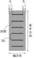
- FIG. 1A is a schematic view showing an embodiment of the present invention in which a recess is formed at a central portion excluding each region from the both ends in the width direction of the Fe-based amorphous alloy ribbon to distances a and b with a distance DL. is there.
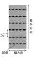
- FIG. 1B is a schematic diagram showing a conventional embodiment in which a recess is formed in the entire width direction of the Fe-based amorphous alloy ribbon.
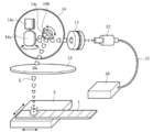
- FIG. 2 is a schematic configuration diagram showing an example of a laser beam irradiation apparatus that can be used for manufacturing the wound magnetic core of the present invention.
- FIG. 3 is a schematic sectional view schematically showing a recess formed in the Fe-based amorphous alloy ribbon.
- FIG. 4 is a schematic plan view schematically showing the recesses formed in the Fe-based amorphous alloy ribbon.
- FIG. 5-A is a photomicrograph showing the recess and its peripheral shape when the laser irradiation energy is 0.3 mJ / Pulse.
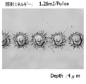
- FIG. 5-B is a photomicrograph showing the recess and its peripheral shape when the laser irradiation energy is 1.26 mJ / Pulse.
- FIG. 6 is a schematic cross-sectional view conceptually showing an embodiment of a production apparatus for producing an Fe-based amorphous alloy ribbon.
- FIG. 7 is a schematic view of a magnetic core having a rectangular winding core and a joint.
- the present invention is a wound magnetic core having a recess array composed of a plurality of recesses formed by laser irradiation at the center in the width direction of an Fe-based amorphous alloy ribbon, wound around an Fe-based amorphous alloy ribbon. is there.
- the present invention does not irradiate the laser over the entire width, but even if the central portion is irradiated with the laser leaving the end in the width direction. It has been found that the effect of the conversion can be obtained.
- laser irradiation is performed with the ratio of the length of the central portion in the width direction when the total width length of the Fe-based amorphous alloy ribbon is set to 1 to 0.2 or more and 0.8 or less.
- the frequency of laser processing is reduced and the number of man-hours can be reduced, the laser processing speed per unit length in the casting direction (longitudinal direction) of the Fe-based amorphous alloy ribbon can be increased, and productivity is effectively improved. Can be improved.
- the wound magnetic core thus obtained has a low iron loss.
- the manufacturing method of the wound magnetic core of the present invention is not limited as long as it has the above configuration, but preferably the ratio of the length to the total width in the width direction of the Fe-based amorphous alloy ribbon is 0.2 or more and 0.
- a winding step in which a band is wound to make a magnetic core and a method (a method for manufacturing a wound core according to the present invention).
- each step will be described.
- a recess is formed by irradiating a laser in a pulsed manner at the center of a predetermined range in the width direction of the Fe-based amorphous alloy ribbon.
- a recess array composed of a plurality of recesses can be provided.
- the ratio of the central portion of the predetermined range to the total width length of the Fe-based amorphous alloy ribbon is 0.2 or more and 0.8 or less (that is, a length of 20% to 80% of the total width of the Fe-based amorphous alloy ribbon).
- the concave portion is formed by irradiating the laser in a pulse shape only to the central portion of the predetermined range.
- the magnetic core produced by laser processing the region of 0.2 to 0.8 in the total width length 1 is Fe-based amorphous alloy while reducing man-hours.
- a low iron loss equal to or higher than that obtained by laser processing of the entire width of the ribbon is obtained. The reason why low iron loss is obtained is not necessarily clear, but it is assumed that complicated factors such as the behavior of magnetic domains in the magnetic core overlap.
- a magnetic core having a low iron loss can be obtained when a magnetic core is formed by selectively performing laser treatment on a central region excluding an end in the width direction of the alloy ribbon.
- the ratio with respect to the total width length is 0.2 or more and 0.8 or less represents the range of the “central portion” where man-hours can be reduced. That is, in the present invention, when the ratio of the length of the central portion to the total width length 1 is in a range exceeding 0.8, the laser is produced while exhibiting the effect of reducing the iron loss as compared with the conventional method in which the entire width is laser processed The advantage which can reduce the man-hour to process will be impaired. Further, if the ratio of the length of the central portion with respect to the total width length 1 is less than 0.2, the amount of laser processing is too short compared with the conventional laser processing, and the effect of the laser processing (magnetic core) (Loss reduction) is reduced.
- the ratio of the central portion of the predetermined range to the full width of the Fe-based amorphous alloy ribbon is preferably in the range of 0.4 to 0.8, and more preferably in the range of 0.4 to 0.8. A range of 6 or less is more preferable.
- the laser irradiation interval in the longitudinal direction of the alloy ribbon in other words, the interval (DL) of the recess rows formed in the longitudinal direction of the alloy ribbon is 2 mm or more and 20 mm or less. It is preferable. Thereby, further reduction in iron loss becomes possible.
- the diameter of the recess and the depth of the recess can be controlled.
- the pulse laser beam is scanned and irradiated in the ribbon width direction.
- a YAG laser, a CO 2 gas laser, a fiber laser, or the like can be used as the laser light source.
- a fiber laser is preferable in that it can stably irradiate high-power and high-frequency pulsed laser light for a long time.
- the laser light introduced into the fiber oscillates on the principle of FBG (Fiber Bragg grating) by the diffraction gratings at both ends of the fiber.
- FBG Fiber Bragg grating
- the laser light is excited in an elongated fiber, there is no problem of the thermal lens effect in which the beam quality is deteriorated due to a temperature gradient generated inside the crystal. Furthermore, since the fiber core is as thin as several microns, the laser light not only propagates in a single mode even at a high output, but also the beam diameter is reduced, and a laser beam with a high energy density can be obtained. In addition, since the depth of focus is long, it is possible to form the recess rows with high accuracy even on a thin ribbon having a width of 200 mm or more.
- the pulse width of a fiber laser is usually about microseconds to picoseconds, but femtosecond level pulses can also be used.
- the wavelength of the laser beam is about 250 nm to 1100 nm depending on the laser light source, but a wavelength of 900 to 1100 nm is preferable because it is sufficiently absorbed by the alloy ribbon.
- the beam diameter of the laser beam is preferably 10 ⁇ m or more, more preferably 20 ⁇ m or more, and most preferably 30 ⁇ m or more.
- the beam diameter is preferably 300 ⁇ m or less, more preferably 100 ⁇ m or less, and most preferably 90 ⁇ m or less.
- This apparatus includes a laser oscillator (Farber laser) 10, a collimator 12, a beam expander 13, a galvano scanner 14, and an f ⁇ lens 15.
- Pulsed laser light L (for example, wavelength 1065 nm) generated by the laser transmitter is transmitted to the collimator 12 by the fiber 11 and is converted into parallel light there.
- the parallel laser beam L is enlarged in diameter by the beam expander 13, passes through the galvano scanner 14, is condensed by the f ⁇ lens 15, and is placed on the table 5 that is movable in the X-axis direction and the Y-axis direction.
- the irradiated amorphous alloy ribbon 1 is irradiated.
- the galvano scanner 14 includes mirrors 14a and 14b that can rotate about the X axis and the Y axis, and each mirror 14a and 14b is driven by a galvano motor 14c. By combining the mirrors 14a and 14b, the pulsed laser beam L can be scanned in the width direction at a predetermined interval in the longitudinal direction of the alloy thin tie.
- a polygon scanner (not shown) provided with a polygon mirror at the tip of the motor may be used.
- the Fe-based amorphous alloy ribbon moves in the longitudinal direction. Is preferably inclined at a predetermined angle with respect to the width direction.
- the laser irradiation is preferably performed while the Fe-based amorphous alloy ribbon is moved intermittently in the longitudinal direction.
- an Fe-based amorphous alloy ribbon is produced by a rapid solidification method, it may be performed before the Fe-based amorphous alloy ribbon is wound on a reel.
- the Fe-based amorphous partly melts or evaporates, and the melted part remaining after the laser treatment resolidifies, so that local strain is introduced.
- the soft magnetic characteristics of the Fe-based amorphous sensitive to strain deteriorate and hysteresis loss increases, resulting in an increase in iron loss.
- the present invention in which the concave portion is provided by selectively performing laser treatment only on the central portion in the width direction has an effect of suppressing an increase in hysteresis loss due to the introduction of local strain by the laser treatment.
- the configuration in which the region having the predetermined width from the end portion in the width direction of the ribbon is left without providing the recess is the conventional configuration in which the entire recess from the one end to the other end in the width direction is provided as shown in FIG.
- the time for performing the laser treatment of the Fe-based amorphous alloy ribbon can be shortened, which greatly contributes to the improvement of the productivity of the laser treatment.
- the interval between the concave portions provided in the ribbon by laser irradiation is preferably an interval of 4 / mm to 8 / mm in the width direction of the ribbon.
- the reduction effect of iron loss is large because the formation interval of the recesses is within this range. It is considered that the magnetic domains are subdivided by forming the recesses because the number of the recesses is not too small and is 4 / mm or more. In addition, since the number of recesses is not too many and is 8 pieces / mm or less, productivity can be maintained high, local strain introduced by the influence of laser processing can be suppressed, and hysteresis loss can be kept low. be able to .
- the formation interval (DL) in the longitudinal direction of the recesses is preferably 2 mm or more, and more than 2 mm Is more preferable, and 5 mm or more is still more preferable.
- DL is preferably 20 mm or less.
- the DL is 2 mm or more, the effect of reducing the iron loss and improving the productivity is large, and the effect of reducing the iron loss appears better in the range exceeding 2 mm.
- DL is 20 mm or less, it is excellent in the low iron loss effect by a laser process, and is advantageous at the point of productivity improvement.
- a more preferable range of DL is 5 mm to 10 mm.
- the plurality of recesses have the same center distance between the recesses. It is considered that the magnetic domains are subdivided by forming the recesses because the intervals between the recesses are uniform. Note that “equal” includes not only the case where the center-to-center distances are exactly the same, but also the case where a plurality of center-to-center distances are not exactly the same, but only a difference that can be regarded as the same distance.
- the shape of the recess formed in the Fe-based amorphous alloy ribbon is not particularly limited.
- any shape such as a circle, an ellipse, a square, a rectangle, a rhombus, and a parallelogram can be selected. it can.
- a circular shape or an elliptical shape is preferable from the viewpoint of formation by laser irradiation or ease of formation.
- the circular shape does not necessarily need to be a perfect circle, and may be a distorted circle or an ellipse.
- the degree of distortion is preferably such that the ratio of the major axis Da to the minor axis Db (Da / Db) is within 1.5.
- FIG. 3 is a schematic explanatory view schematically showing a cross section of the circular recess 2 formed in the Fe-based amorphous alloy ribbon and the surrounding annular protrusion 3.
- FIG. 4 is a schematic plan view schematically showing the shape of the concave portion of FIG. 3 when viewed in plan.
- the diameter D1 of the recessed part 2 is a diameter of the opening part of the recessed part 2 in the position which cross
- the depth t1 of the recess 2 is the distance between the straight line 1a and the bottom of the recess 2.
- An outer shape D2 of the annular projecting portion 3 is an outer shape of the annular projecting portion at a position intersecting the straight line 1a.
- the height t2 of the annular projecting portion is the distance between the straight line 1a and the apex of the annular projecting portion 3.
- the width W of the annular protrusion 3 is the width ((D2-D1) / 2) of the annular protrusion 3 at a position intersecting the straight line 1a.
- Each of these parameters is represented by an average value of values obtained from the recesses 2 and the annular protrusions 3 in the plurality of recess rows in the width direction.
- the maximum diameter can be in the range of 30 ⁇ m to 120 ⁇ m, preferably in the range of 35 ⁇ m to 70 ⁇ m. Can do. It is considered that the magnetic domains are subdivided by forming the concave portions when the size of the concave portions is not too small and is 30 ⁇ m or more. Moreover, since the size of the recess is not too large and is 120 ⁇ m or less, the local strain introduced due to the influence of the laser processing can be suppressed, and the hysteresis loss can be kept low.
- the depth of the recess formed in the Fe-based amorphous alloy ribbon can be in the range of 1 ⁇ m or more, and preferably in the range of 2 ⁇ m or more. Further, the depth of the concave portion can be in a range of 5 ⁇ m or less, and preferably in a range of 4 ⁇ m or less. It is considered that the effect of reducing and subdividing the iron loss magnetic domain in the wound magnetic core due to the formation of the recess is promoted by the depth of the recess being 2 ⁇ m or more without being too shallow.
- the laser processing can be speeded up, the local strain introduced by the influence of the laser processing can be suppressed, and the hysteresis loss can be kept low. Thereby, an iron loss can be suppressed low.
- the portion where the concave portion is formed by the laser treatment has an annular bulge, and the scattered matter does not adhere to the periphery after the Fe-based amorphous alloy is melted or evaporated by the laser.
- the Fe-based amorphous alloy ribbon preferably has a reflectance (R) in the range of 50% to 80% at a wavelength ( ⁇ ) of 1000 nm on the ribbon surface.
- ⁇ represents the amount of light flux that is perpendicularly incident on the surface of the ribbon
- ⁇ r represents the amount of light beam that is reflected in the incident direction on the surface of the ribbon.
- ⁇ and ⁇ r are values measured at a wavelength of 1000 nm using a spectrophotometer (JASCO V-570 manufactured by JASCO Corporation).
- the Fe-based amorphous alloy ribbon alloy constituting the wound magnetic core of the present invention includes Fe—B, Fe—Si—B, Fe—Si—BC, Fe—Si—BP, Fe— A —Si—B—C—P system, Fe—P—B system, or the like can be applied.
- Fe—Si—B and Fe—Si—B—C based alloys are preferable because they are not easily embrittled even by laser irradiation and are easy to process such as cutting.
- the Fe—Si—B amorphous alloy is a system containing 2 atomic% to 13 atomic% of Si and 8 atomic% to 16 atomic% of B, with the balance being substantially Fe and inevitable impurities. Alloys are preferred.
- Fe—Si—B—C system amorphous alloy contains 2 atomic% to 13 atomic% Si, 8 atomic% to 16 atomic% B, and 3 atomic% or less C, with the balance being Fe and inevitable impurities
- the amount of C is preferably 0.3 atomic percent or less.
- the Fe-based amorphous alloy has a total proportion of 5 atomic% or less with respect to the amount of Fe, Co, Ni, Mn, Cr, V, Mo, Nb, Ta, Hf, Zr, Ti, Cu, Au.
- An element selected from the group consisting of Ag, Sn, Ge, Re, Ru, Zn, In, and Ga may be contained.
- the thickness of the Fe-based amorphous alloy ribbon is preferably in the range of 15 ⁇ m or more, and more preferably in the range of 20 ⁇ m or more.
- the thickness is preferably in the range of 40 ⁇ m or less, more preferably in the range of 35 ⁇ m or less, and further preferably in the range of 30 ⁇ m or less.
- the thickness is 15 ⁇ m or more, it is advantageous in that the mechanical strength of the ribbon can be maintained, the space factor can be increased, and the number of layers when wound around the winding core is reduced.
- the thickness of 40 ⁇ m or less is advantageous in that eddy current loss can be suppressed to a small value, and bending distortion when processed into a wound core is reduced, and an amorphous phase can be obtained stably.
- the length (width length) in the width direction orthogonal to the longitudinal direction (casting direction) of the Fe-based amorphous alloy ribbon is preferably 15 mm or more and 250 mm or less.
- the width is 15 mm or more, a large-capacity magnetic core is easily obtained.
- the width is 250 mm or less, an alloy ribbon having a uniform thickness in the width direction is easily obtained.
- the width is preferably 50 mm or more and 220 mm or less.
- the production (casting) of the Fe-based amorphous alloy ribbon can be performed by a known method such as a liquid quenching method (single roll method, twin roll method, centrifugal method, etc.).
- a liquid quenching method single roll method, twin roll method, centrifugal method, etc.
- the single roll method is a manufacturing method with relatively simple manufacturing equipment and capable of stable manufacturing, and has excellent industrial productivity.
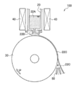
- FIG. 6 is a schematic cross-sectional view conceptually showing an example of an Fe-based amorphous alloy ribbon manufacturing apparatus for manufacturing an Fe-based amorphous alloy ribbon.
- FIG. 6 shows the Fe-based amorphous alloy ribbon manufacturing apparatus 100 in a plane perpendicular to the axial direction of the cooling roll 30 and the width direction of the Fe-based amorphous alloy ribbon 22C (these two directions are the same). The cross section when cut is shown.
- An Fe-based amorphous alloy ribbon manufacturing apparatus 100 shown in FIG. 6 is an Fe-based amorphous alloy ribbon manufacturing apparatus using a single roll method, and a crucible 20 having a molten metal nozzle 10 and a surface thereof facing the tip of the molten metal nozzle 10. And a cooling roll 30 to be provided.
- the crucible 20 has an internal space that can accommodate the molten alloy 22A as a raw material for the Fe-based amorphous alloy ribbon, and the internal space and the molten metal flow path in the molten metal nozzle 10 communicate with each other. Thereby, the molten alloy 22A accommodated in the crucible 20 can be discharged to the cooling roll 30 by the molten metal nozzle 10 (in FIG. 6, the discharge direction and the flow direction of the molten alloy 22A are indicated by arrows Q). )
- the crucible 20 and the molten metal nozzle 10 may be comprised integrally, and may be comprised as a different body.
- a high frequency coil 40 as a heating means is disposed at least at a part of the periphery of the crucible 20.
- the molten metal nozzle 10 has an opening (discharge port) for discharging the molten alloy. It is preferable that the opening has a rectangular (slit shape) opening. The length of the long side of the rectangular opening is a length corresponding to the width of the Fe-based amorphous alloy ribbon to be manufactured.
- the distance between the tip of the molten metal nozzle 10 and the surface of the cooling roll 30 is close enough to form the hot water pool 22B formed by the molten alloy 22A when the molten molten metal 22A is discharged by the molten metal nozzle 10.
- this distance can be made into the range normally set in a single roll method, 500 micrometers or less are preferable, 300 micrometers or less are more preferable, and 200 micrometers or less are especially preferable.
- This distance is preferably 50 ⁇ m or more from the viewpoint of suppressing contact between the tip of the molten metal nozzle 10 and the surface of the cooling roll 30.
- the cooling roll 30 is configured to be able to rotate in the direction of the arrow P. Inside the cooling roll 30, a cooling medium such as water is circulated. Thereby, the molten alloy 22A applied (discharged) to the surface of the cooling roll 30 can be cooled to manufacture (cast) the Fe-based amorphous alloy ribbon 22C.
- the material of the cooling roll 30 is heat conductivity selected from Cu and Cu alloys (Cu—Be alloy, Cu—Cr alloy, Cu—Zr alloy, Cu—Zn alloy, Cu—Sn alloy, Cu—Ti alloy, etc.). It is preferable that the material is high.
- the surface roughness of the surface of the cooling roll 30 is not particularly limited, but from the viewpoint of the space factor, the arithmetic average roughness (Ra) of the surface of the cooling roll 30 is preferably 0.5 ⁇ m or less, and 0.3 ⁇ m. The following is more preferable.
- the arithmetic average roughness (Ra) of the surface of the cooling roll 30 is preferably 0.1 ⁇ m or more from the viewpoint of workability for adjusting the surface roughness.
- the surface of the cooling roll 30 may be polished with a brush or the like during the production of the alloy ribbon.
- the surface roughness (the arithmetic average roughness Ra) refers to the surface roughness measured according to JIS B 0601 (2001).
- the cooling roll 30 the cooling roll normally used in a single roll method can be used.
- the diameter of the cooling roll 30 is preferably 200 mm or more, and more preferably 300 mm or more, from the viewpoint of cooling ability.
- the diameter is preferably 700 mm or less.
- the rotation speed of the cooling roll 30 can be in a range that is normally set in the single roll method. A higher peripheral speed is better for productivity, but a peripheral speed of 40 m / s or less is preferable to maintain stable rotation of the roll.
- the peripheral speed is preferably 10 m / s or more, and more preferably 20 m / s or more.
- the upper limit is more preferably a circumferential speed of 35 m / s or less, and even more preferably a circumferential speed of 30 m / s or less.
- the temperature of the surface of the cooling roll 30 is a stable temperature from the start of casting.
- the cooling rate of the molten alloy by the cooling roll 30 is preferably 1 ⁇ 10 5 ° C./s or more, more preferably 1 ⁇ 10 6 ° C./s or more in order to stably obtain an amorphous alloy ribbon.
- the operations from discharging the molten alloy to winding (recovering) the Fe-based amorphous alloy ribbon are continuously performed. Thereby, for example, a long Fe-based amorphous alloy ribbon having a length in the longitudinal direction of 3000 m or more is obtained.
- a peeling gas nozzle 50 is disposed in the vicinity of the surface of the cooling roll 30 (on the downstream side of the molten metal nozzle 10 in the rotation direction of the cooling roll 30).
- a stripping gas for example, high-pressure gas such as nitrogen gas or compressed air
- peeling of the Fe-based amorphous alloy ribbon 22C from the roll 30 is performed more efficiently.
- the Fe-based amorphous alloy ribbon is subjected to heat treatment in a temperature range of 300 ° C to 400 ° C.
- the heat treatment is preferably performed by applying a magnetic field of 200 A / m or more, more preferably 400 A / m or more in the circumferential direction of the magnetic core.
- the magnetic core is manufactured by winding the Fe-based amorphous alloy ribbon in which the recess is formed in the recess forming process.
- a magnetic core is produced by winding around a predetermined core material while applying a predetermined tensile stress.
- the tensile stress at the time of winding can usually be in a range of 2N to 20N, and is preferably performed under a certain degree of stress in view of the effect of the present invention.
- the tensile stress at the time of winding is preferably in the range of 4N to 12N.
- the wound core of the present invention is produced by winding an alloy ribbon that has been laser-processed at the center in the width direction of the Fe-based amorphous alloy ribbon, and the width direction of the Fe-based amorphous alloy ribbon. In the central portion, the ratio of the length to the total width is 0.2 or more and 0.8 or less, and a recess row composed of a plurality of recesses formed by laser irradiation is provided.
- the wound core of the present invention may be manufactured by any method as long as it has such a configuration, and is preferably manufactured by the above-described method for manufacturing a wound core of the present invention.
- the shape of the wound magnetic core of the present invention is not limited to a circle, but may be a rectangle as shown in FIG.
- the wound core of the present invention may be made from a plurality of Fe-based amorphous alloy ribbons. Furthermore, the wound magnetic core of the present invention may have an overlap or a back trap joint.
- an Fe-based amorphous alloy ribbon manufacturing apparatus configured similarly to the manufacturing apparatus 100 shown in FIG. 6 was prepared.
- the following cooling rolls were used.
- a molten alloy composed of Fe, Si, B, C and unavoidable impurities (hereinafter also referred to as an Fe—Si—BC alloy melt) was prepared in a crucible.
- a Fe-based amorphous alloy ribbon having the above composition is manufactured by melting a master alloy composed of Fe, Si, B, and unavoidable impurities, adding carbon to the resulting molten metal, and mixing and dissolving the resultant alloy.
- a molten alloy was prepared for this purpose.
- this Fe—Si—B—C-based alloy melt is rotated from the opening of a melt nozzle having a rectangular (slit shape) opening having a long side length of 25 mm and a short side length of 0.6 mm. It was discharged onto the surface of a cooling roll and rapidly solidified to produce a 30 kg Fe-based amorphous alloy ribbon having a width of 25 mm and a thickness of 24 ⁇ m.
- Cooling roll ⁇ Material: Cu—Be alloy ⁇ Diameter: 400 mm -Arithmetic mean roughness Ra of the cooling roll surface: 0.3 ⁇ m ⁇ Discharge pressure of molten alloy: 20kPa ⁇ Cooling roll peripheral speed: 25 m / s -Molten metal temperature: 1300 ° C ⁇ Distance between molten metal nozzle tip and cooling roll surface: 200 ⁇ m
- Example 1 On the free solidification surface of the Fe 81.7 Si 2 B 16 C 0.3 alloy ribbon obtained above, a wavelength: 1065 nm from a fiber laser through a galvano scanner (mirror) as shown in FIG. A pulse laser beam having a pulse width of 550 ns and a beam diameter of 60 ⁇ m is scanned so that the laser beam is not irradiated onto a region at a predetermined distance from both ends in the ribbon width direction, and a recess array is formed in the central portion in the ribbon width direction. Formed. The irradiation energy at this time was set to 0.3 mJ / Pulse or 1.26 mJ / Pulse.
- the example of the concave portion is formed by changing the irradiation energy by two types, and as shown in FIG. 1-A, the central portion excluding the region from the both ends in the width direction to 5 mm (the ratio of the length to the total width length: 0) .6) a total of four types of samples including a plurality of recesses and a sample having recesses formed in the entire width direction as shown in FIG. Sample 4) was prepared. Further, a ribbon sample 1 that was not subjected to laser processing was prepared as a comparative material.
- the interval (number density) of the recesses in the recess row in the width direction was 6 pieces / mm, and the interval DL between the recess rows in the longitudinal direction of the ribbon was 5 mm.
- the time required for laser processing under each condition when the time required for laser processing over the entire ribbon width direction at a recess depth [ ⁇ m] and 1.26 mJ / Pulse is 100, As shown in Table 1 below.
- FIG. 5-A shows the recess and its surrounding shape when the irradiation energy is 0.3 mJ / Pulse
- FIG. 5-B shows the recess and its surrounding shape when the irradiation energy is 1.26 mJ / Pulse. Indicates.
- the ribbon sample 2 to the ribbon sample 5 subjected to the laser treatment showed a lower iron loss than the ribbon sample 1 not subjected to the laser treatment.
- the ribbon sample 4 having a higher irradiation energy at each magnetic flux density. Showed lower iron loss.
- the ribbon sample 5 with higher irradiation energy showed lower iron loss.
- the ribbon samples 2 and 4 irradiated with the laser in the entire width direction, and the ribbon samples 3 and 5 irradiated with the laser at the central portion excluding 5 mm from both ends in the width direction As shown in Table 3, in the thin ribbon sample 2 and the thin ribbon sample 3, the thin ribbon sample 3 irradiated with laser at the center portion has a lower iron loss, and the thin ribbon sample 4 and the thin ribbon sample 3 are thin. In contrast to the strip sample 5, it can be seen that the thin strip sample 5 has a larger iron loss.
- the superiority in the case where only the central portion is irradiated with laser over the entire width direction cannot be confirmed.
- the iron loss was measured by winding the primary winding and the secondary winding around a magnetic core and changing the excitation magnetic flux density in the range of 1.35 T to 1.50 T at a frequency of 50 Hz.
- the measurement results are shown in Table 3 below.
- the sample numbers of the wound cores in Table 3 correspond to the ribbon sample Nos.
- the wound magnetic cores 2 to 5 manufactured using the ribbon sample 2 to the ribbon sample 5 subjected to the laser treatment have a lower iron content at each magnetic flux density than the wound core 1 using the laser-treated ribbon sample 1. It was a loss. Also, iron loss is compared for each irradiation energy. In the ribbon materials 2 and 3 in which the irradiation energy is 0.3 mJ / Pulse, the winding core 3 of the present invention using the ribbon sample 3 is a comparative winding core using the ribbon sample 2 at each magnetic flux density. Compared to 2, the iron loss was lower.
- the wound core 5 of the present invention using the ribbon sample 5 is a comparative wound core using the ribbon sample 4 at each magnetic flux density. Compared to 4, it was equivalent or low iron loss.
- the wound core 5 of the present invention using the ribbon sample 5 at B 1.50 (T), for example, is more in comparison with the comparative winding core 4 using the ribbon sample 4 and the ribbon sample 3.
- the wound core 3 of the present invention using the iron loss of 0.01 W / kg was obtained.
- Example 2 In Example 1, except that the laser processing conditions were changed as shown in Table 4 below, a recess row was formed in the central portion in the ribbon width direction in the same manner as in Example 1, and FIG. As shown, samples (thin strip samples 7 to 13) in which a plurality of recesses were formed in the central portion excluding a predetermined region from both ends in the width direction (see Table 4 for the ratio of the length to the total width length 1) were prepared. . At this time, the irradiation energy was 0.3 mJ / Pulse, and the interval (number density) of the recesses was 6 / mm.
- wound cores were produced and heat-treated in the same manner as in Example 1.
- conditions such as temperature and DC magnetic field application were the same, but different heat treatment furnaces were used.
- the iron loss was measured by winding the primary winding and the secondary winding around a magnetic core, and changing the excitation magnetic flux density in the range of 1.35 (T) to 1.50 (T) at a frequency of 50 Hz.
- the measurement results are shown in Table 5 below.
- the sample Nos. Of the wound cores in Table 5 correspond to the ribbon sample Nos. In Table 4, respectively.
- the magnetic cores 8 to 10 had lower iron loss at each magnetic flux density than the wound magnetic core 6 using the laser-untreated ribbon sample 6.
- the wound cores 8 to 10 are compared with the wound core 7 using the thin ribbon sample 7 irradiated with laser at the central portion (length ratio to the total width length: 0.92) excluding 1 mm from both ends in the width direction. At each magnetic flux density, the iron loss was low.
- the wound magnetic cores 8, 11, 12 are approximately at each magnetic flux density.
- 13 all had a lower iron loss than the wound core 6.
- the recess formation interval DL in the longitudinal direction of the ribbon is preferably 2 mm or more.
- the present invention is suitable for fields such as a distribution transformer, a high-frequency transformer, a saturable reactor, and a magnetic switch.
Landscapes
- Engineering & Computer Science (AREA)
- Physics & Mathematics (AREA)
- Optics & Photonics (AREA)
- Plasma & Fusion (AREA)
- Mechanical Engineering (AREA)
- Power Engineering (AREA)
- Manufacturing & Machinery (AREA)
- Electromagnetism (AREA)
- Chemical & Material Sciences (AREA)
- Dispersion Chemistry (AREA)
- Manufacturing Cores, Coils, And Magnets (AREA)
- Soft Magnetic Materials (AREA)
Abstract
Priority Applications (4)
| Application Number | Priority Date | Filing Date | Title |
|---|---|---|---|
| CN201480014465.0A CN105074841B (zh) | 2013-03-13 | 2014-03-12 | 卷绕磁芯和其制造方法 |
| US14/774,703 US9978497B2 (en) | 2013-03-13 | 2014-03-12 | Wound magnetic core and method of producing the same |
| JP2015505530A JP6350516B2 (ja) | 2013-03-13 | 2014-03-12 | 巻磁心及びその製造方法 |
| KR1020157026281A KR102123138B1 (ko) | 2013-03-13 | 2014-03-12 | 권자심 및 그 제조 방법 |
Applications Claiming Priority (2)
| Application Number | Priority Date | Filing Date | Title |
|---|---|---|---|
| JP2013-051035 | 2013-03-13 | ||
| JP2013051035 | 2013-03-13 |
Publications (1)
| Publication Number | Publication Date |
|---|---|
| WO2014142204A1 true WO2014142204A1 (fr) | 2014-09-18 |
Family
ID=51536855
Family Applications (1)
| Application Number | Title | Priority Date | Filing Date |
|---|---|---|---|
| PCT/JP2014/056575 Ceased WO2014142204A1 (fr) | 2013-03-13 | 2014-03-12 | Noyau magnétique enroulé et procédé pour sa fabrication |
Country Status (5)
| Country | Link |
|---|---|
| US (1) | US9978497B2 (fr) |
| JP (1) | JP6350516B2 (fr) |
| KR (1) | KR102123138B1 (fr) |
| CN (1) | CN105074841B (fr) |
| WO (1) | WO2014142204A1 (fr) |
Cited By (4)
| Publication number | Priority date | Publication date | Assignee | Title |
|---|---|---|---|---|
| WO2019189813A1 (fr) * | 2018-03-30 | 2019-10-03 | 日立金属株式会社 | RUBAN D'ALLIAGE AMORPHE À BASE DE Fe ET SON PROCÉDÉ DE PRODUCTION, NOYAU DE FER ET TRANSFORMATEUR |
| JP2020515059A (ja) * | 2017-03-09 | 2020-05-21 | フォエスタルピネ オートモーティブ コンポーネンツ デッティンゲン ゲーエムベーハー アンド コーポレーション カーゲー | 鋼板パーツを結合して鋼板積層体にするための装置及び方法 |
| WO2022092119A1 (fr) * | 2020-10-26 | 2022-05-05 | 日本製鉄株式会社 | Noyau de fer enroulé, procédé de fabrication de noyau de fer enroulé et dispositif de fabrication de noyau de fer enroulé |
| RU2805262C1 (ru) * | 2020-10-26 | 2023-10-13 | Ниппон Стил Корпорейшн | Ленточный сердечник, способ изготовления ленточного сердечника и устройство изготовления ленточных сердечников |
Families Citing this family (16)
| Publication number | Priority date | Publication date | Assignee | Title |
|---|---|---|---|---|
| WO2014142204A1 (fr) * | 2013-03-13 | 2014-09-18 | 日立金属株式会社 | Noyau magnétique enroulé et procédé pour sa fabrication |
| US20160172087A1 (en) * | 2014-12-11 | 2016-06-16 | Metglas, Inc. | Fe-Si-B-C-BASED AMORPHOUS ALLOY RIBBON AND TRANSFORMER CORE FORMED THEREBY |
| KR20170053480A (ko) * | 2015-11-06 | 2017-05-16 | 엘지이노텍 주식회사 | 연자성 합금 |
| JP6596393B2 (ja) * | 2016-07-25 | 2019-10-23 | 株式会社村田製作所 | コイル部品の製造装置 |
| KR20190117617A (ko) | 2017-02-14 | 2019-10-16 | 히타치 긴조쿠 가부시키가이샤 | Fe기 아몰퍼스 합금 리본의 제조 방법, Fe기 아몰퍼스 합금 리본의 제조 장치, 및 Fe기 아몰퍼스 합금 리본의 권회체 |
| KR102451085B1 (ko) * | 2017-03-31 | 2022-10-05 | 히타치 긴조쿠 가부시키가이샤 | Fe기 나노 결정 합금용의 Fe기 아몰퍼스 합금 리본 및 그 제조 방법 |
| US12070794B2 (en) * | 2018-09-26 | 2024-08-27 | Proterial, Ltd. | Method for producing Fe-based nanocrystalline alloy ribbon, method for producing magnetic core, Fe-based nanocrystalline alloy ribbon, and magnetic core |
| US20220106215A1 (en) * | 2019-01-17 | 2022-04-07 | Corning Incorporated | Glass manufacturing apparatus and methods |
| US11802328B2 (en) | 2019-06-28 | 2023-10-31 | Proterial, Ltd. | Fe-based amorphous alloy ribbon, iron core, and transformer |
| CN112582148B (zh) * | 2019-09-30 | 2024-11-29 | 株式会社博迈立铖 | 变压器 |
| US12115596B2 (en) * | 2020-01-27 | 2024-10-15 | National Technology & Engineering Solutions Of Sandia, Llc | Methods for site-specific enhancement of soft magnetic alloys |
| JP2021159940A (ja) * | 2020-03-31 | 2021-10-11 | Tdk株式会社 | 合金薄帯、積層コア |
| JP7615748B2 (ja) * | 2021-02-19 | 2025-01-17 | セイコーエプソン株式会社 | 非晶質金属薄帯、非晶質金属薄帯の製造方法および磁心 |
| JP7790041B2 (ja) * | 2021-07-16 | 2025-12-23 | セイコーエプソン株式会社 | 軟磁性合金薄帯、軟磁性合金薄帯の製造方法および磁心 |
| CN115351429B (zh) * | 2022-09-15 | 2024-12-27 | 宁波中益赛威新材料有限公司 | 铁基非晶、纳米晶制备方法 |
| CN119634997B (zh) * | 2024-12-05 | 2025-08-22 | 南京师范大学 | 一种基于脉冲激光技术提高铁基非晶合金压磁系数的方法 |
Citations (5)
| Publication number | Priority date | Publication date | Assignee | Title |
|---|---|---|---|---|
| JPS5316802A (en) * | 1976-06-10 | 1978-02-16 | Workman John | Dc motor pole support structure and method of manufacturing it |
| JPS5858845A (ja) * | 1981-09-30 | 1983-04-07 | Shibaura Eng Works Co Ltd | ブラシレスモ−タ |
| JPH04367202A (ja) * | 1991-06-14 | 1992-12-18 | Nippon Steel Corp | 軟磁気特性のすぐれたFe基非晶質合金薄帯およびその 製造方法 |
| WO2011030907A1 (fr) * | 2009-09-14 | 2011-03-17 | 日立金属株式会社 | Ruban en alliage amorphe magnétique souple, procédé pour sa fabrication et noyau magnétique l'utilisant |
| WO2012102379A1 (fr) * | 2011-01-28 | 2012-08-02 | 日立金属株式会社 | Ruban en alliage magnétique doux à base de fe traité par trempe rapide, procédé de fabrication du ruban en alliage, et noyau de fer |
Family Cites Families (5)
| Publication number | Priority date | Publication date | Assignee | Title |
|---|---|---|---|---|
| US4724015A (en) * | 1984-05-04 | 1988-02-09 | Nippon Steel Corporation | Method for improving the magnetic properties of Fe-based amorphous-alloy thin strip |
| TW198154B (fr) * | 1991-08-20 | 1993-01-11 | Allied Signal Inc | |
| TWI305548B (en) * | 2005-05-09 | 2009-01-21 | Nippon Steel Corp | Low core loss grain-oriented electrical steel sheet and method for producing the same |
| KR101041774B1 (ko) | 2009-09-18 | 2011-06-17 | 원정희 | 공기조화시스템의 공조용 여과필터 |
| WO2014142204A1 (fr) * | 2013-03-13 | 2014-09-18 | 日立金属株式会社 | Noyau magnétique enroulé et procédé pour sa fabrication |
-
2014
- 2014-03-12 WO PCT/JP2014/056575 patent/WO2014142204A1/fr not_active Ceased
- 2014-03-12 CN CN201480014465.0A patent/CN105074841B/zh active Active
- 2014-03-12 JP JP2015505530A patent/JP6350516B2/ja active Active
- 2014-03-12 US US14/774,703 patent/US9978497B2/en active Active
- 2014-03-12 KR KR1020157026281A patent/KR102123138B1/ko active Active
Patent Citations (5)
| Publication number | Priority date | Publication date | Assignee | Title |
|---|---|---|---|---|
| JPS5316802A (en) * | 1976-06-10 | 1978-02-16 | Workman John | Dc motor pole support structure and method of manufacturing it |
| JPS5858845A (ja) * | 1981-09-30 | 1983-04-07 | Shibaura Eng Works Co Ltd | ブラシレスモ−タ |
| JPH04367202A (ja) * | 1991-06-14 | 1992-12-18 | Nippon Steel Corp | 軟磁気特性のすぐれたFe基非晶質合金薄帯およびその 製造方法 |
| WO2011030907A1 (fr) * | 2009-09-14 | 2011-03-17 | 日立金属株式会社 | Ruban en alliage amorphe magnétique souple, procédé pour sa fabrication et noyau magnétique l'utilisant |
| WO2012102379A1 (fr) * | 2011-01-28 | 2012-08-02 | 日立金属株式会社 | Ruban en alliage magnétique doux à base de fe traité par trempe rapide, procédé de fabrication du ruban en alliage, et noyau de fer |
Cited By (10)
| Publication number | Priority date | Publication date | Assignee | Title |
|---|---|---|---|---|
| JP2020515059A (ja) * | 2017-03-09 | 2020-05-21 | フォエスタルピネ オートモーティブ コンポーネンツ デッティンゲン ゲーエムベーハー アンド コーポレーション カーゲー | 鋼板パーツを結合して鋼板積層体にするための装置及び方法 |
| JP7229930B2 (ja) | 2017-03-09 | 2023-02-28 | フォエスタルピネ オートモーティブ コンポーネンツ デッティンゲン ゲーエムベーハー アンド コーポレーション カーゲー | 鋼板パーツを結合して鋼板積層体にするための装置及び方法 |
| WO2019189813A1 (fr) * | 2018-03-30 | 2019-10-03 | 日立金属株式会社 | RUBAN D'ALLIAGE AMORPHE À BASE DE Fe ET SON PROCÉDÉ DE PRODUCTION, NOYAU DE FER ET TRANSFORMATEUR |
| JPWO2019189813A1 (ja) * | 2018-03-30 | 2020-04-30 | 日立金属株式会社 | Fe基アモルファス合金薄帯及びその製造方法、鉄心、並びに変圧器 |
| US12002607B2 (en) | 2018-03-30 | 2024-06-04 | Proterial, Ltd. | Fe-based amorphous alloy ribbon and method for producing same, iron core, and transformer |
| WO2022092119A1 (fr) * | 2020-10-26 | 2022-05-05 | 日本製鉄株式会社 | Noyau de fer enroulé, procédé de fabrication de noyau de fer enroulé et dispositif de fabrication de noyau de fer enroulé |
| JP7103554B1 (ja) * | 2020-10-26 | 2022-07-20 | 日本製鉄株式会社 | 巻鉄心、巻鉄心の製造方法及び巻鉄心製造装置 |
| TWI778844B (zh) * | 2020-10-26 | 2022-09-21 | 日商日本製鐵股份有限公司 | 捲鐵心、捲鐵心之製造方法及捲鐵心製造裝置 |
| RU2805262C1 (ru) * | 2020-10-26 | 2023-10-13 | Ниппон Стил Корпорейшн | Ленточный сердечник, способ изготовления ленточного сердечника и устройство изготовления ленточных сердечников |
| AU2021369233A9 (en) * | 2020-10-26 | 2024-10-10 | Nippon Steel Corporation | Wound iron core, manufacturing method for wound iron core, and wound iron core manufacturing device |
Also Published As
| Publication number | Publication date |
|---|---|
| CN105074841A (zh) | 2015-11-18 |
| US20160035474A1 (en) | 2016-02-04 |
| US9978497B2 (en) | 2018-05-22 |
| JP6350516B2 (ja) | 2018-07-04 |
| CN105074841B (zh) | 2017-06-16 |
| KR20150131065A (ko) | 2015-11-24 |
| JPWO2014142204A1 (ja) | 2017-02-16 |
| KR102123138B1 (ko) | 2020-06-15 |
Similar Documents
| Publication | Publication Date | Title |
|---|---|---|
| JP6350516B2 (ja) | 巻磁心及びその製造方法 | |
| JP5440606B2 (ja) | 軟磁性アモルファス合金薄帯及びその製造方法、並びにそれを用いた磁心 | |
| JP6806279B2 (ja) | Fe基アモルファス合金薄帯、鉄心、及び変圧器 | |
| JP6041181B2 (ja) | 巻磁心 | |
| JP7331974B2 (ja) | Fe基アモルファス合金薄帯、鉄心、及び変圧器 | |
| CN112582148B (zh) | 变压器 | |
| JP7547958B2 (ja) | アモルファス合金薄帯の製造方法 | |
| JP2021057576A (ja) | 変圧器 | |
| JP7547959B2 (ja) | 積層アモルファス合金薄帯保持スプールの製造方法、および鉄心の製造方法 | |
| JP7790041B2 (ja) | 軟磁性合金薄帯、軟磁性合金薄帯の製造方法および磁心 |
Legal Events
| Date | Code | Title | Description |
|---|---|---|---|
| WWE | Wipo information: entry into national phase |
Ref document number: 201480014465.0 Country of ref document: CN |
|
| 121 | Ep: the epo has been informed by wipo that ep was designated in this application |
Ref document number: 14762763 Country of ref document: EP Kind code of ref document: A1 |
|
| ENP | Entry into the national phase |
Ref document number: 2015505530 Country of ref document: JP Kind code of ref document: A |
|
| WWE | Wipo information: entry into national phase |
Ref document number: 14774703 Country of ref document: US |
|
| NENP | Non-entry into the national phase |
Ref country code: DE |
|
| ENP | Entry into the national phase |
Ref document number: 20157026281 Country of ref document: KR Kind code of ref document: A |
|
| 122 | Ep: pct application non-entry in european phase |
Ref document number: 14762763 Country of ref document: EP Kind code of ref document: A1 |